
Related Manuals for FLENDER S.A Series


Summarization of Contents
Introduction to REDUREX Gear Units
General Information for Operating Instructions
Provides general information about the operating instructions and required knowledge.
Lubricant Recommendations for Gear Units
Details on the type, viscosity, and quantity of lubricants required for the gear unit.
Safety Instructions for Gear Unit Operation
Industrial Security Notes
Information on industrial security functions and protection against cyber threats.
Five Essential Safety Rules
Essential safety rules to follow when working on electrical components.
Gear Unit Symbols and Markings
Explains symbols used on the gear unit and their meanings.
General Warning Symbols and Hazards
Details common warning symbols and their associated hazards.
Specific Dangers and Personal Protective Equipment
Identifies specific dangers and lists required personal protective equipment (PPE).
Intended Use of the Gear Unit
Defines the proper and improper uses of the gear unit.
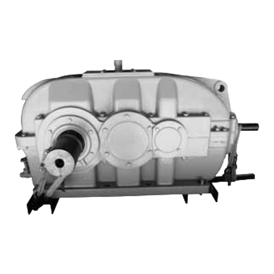
Description of REDUREX Gear Units
General Description of REDUREX Gear Units
Overview of the FLENDER gear unit's development and basic configuration.
REDUREX Gear Unit Housing
Describes the construction and features of the gear unit housing.
Gear Unit Oil Supply Systems
Explains the different methods for supplying oil to the gear unit.
Shaft Seal Types
Describes various types of shaft seals to prevent oil escape or dirt ingress.
Gear Unit Cooling Systems
Covers different cooling equipment options for the gear unit.
Bearing Monitoring Systems
Covers bearing monitoring using Pt 100 thermometers and acceleration sensors.
Application Planning for Gear Units
Scope of Gear Unit Delivery
Lists the items included in the gearbox delivery and how to check them.
Safe Transport of Gear Units
Provides instructions for safely transporting the gear unit to avoid damage.
Gear Unit Attachment Points
Details the correct attachment points for lifting and moving the gear unit.
Gear Unit Lubrication Features
Explains oil filling and draining procedures for different gear unit types.
Mounting Procedures for REDUREX Gear Units
General Assembly Instructions
Covers general precautions and requirements for assembly work.
Unpacking the Gear Unit
Provides instructions for safely unpacking the gear unit upon receipt.
Gear Unit Mounting Procedures
Details the requirements and procedures for mounting the gear unit.
Shaft-Mounted Gear Unit with Hollow Shaft
Details mounting procedures for gear units with hollow shaft and parallel keyway.
Shaft-Mounted Gear Unit with Shrink Disk
Describes mounting and dismantling for units with hollow shaft and shrink disk.
Coupling Installation and Alignment
Details on coupling misalignment and alignment procedures.
Connecting System Components
Instructions for connecting various components like cooling coils and coolers.
Bolt Tightening Procedures
Details bolt properties and connection classes for proper tightening.
Final Work After Mounting
Final checks and tasks after assembly is completed.
Commissioning Procedures for REDUREX Gear Units
Pre-Commissioning Measures
Lists essential checks and preparations before commissioning the gear unit.
Measures During Commissioning
Actions to perform during the commissioning process of the gear unit.
Operation of REDUREX Gear Units
Operating Data and Conditions
Presents valid operating data and conditions for the gear unit and oil.
Irregularities During Operation
Lists common irregular behaviours during operation and immediate actions.
Taking the Unit Out of Service
Procedures for taking the gear unit out of service for prolonged periods.
Maintenance and Servicing of REDUREX Gear Units
General Maintenance Activities
Overview of general maintenance requirements and time limits.
Maintenance Schedule and Activities
Table detailing maintenance and servicing activities at regular intervals.
Maintenance and Service Work Procedures
Detailed procedures for specific maintenance tasks.
Troubleshooting Possible Faults
Lists possible faults and provides a troubleshooting guide.
Service and Support Information
Contact Information for Flender GmbH
Contact information for Flender GmbH for spare parts and technical queries.
Further Service and Support Information
Information on finding further service and support on the Internet.
Disposal of Gear Units and Environmental Protection
Disposal of the Gear Unit
Measures for disposing of the gear unit and its parts after its useful life.
Environmental Protection Measures for Disposal
Environmental protection measures for disposal of oil and packaging materials.
Spare Parts Information
Note on Unsuitable Spare Parts
Warning regarding the use of unsuitable or non-original spare parts.
Information for Ordering Spare Parts
Details on the information needed to order spare parts from Flender.
Quality Documents
Declaration of Incorporation
Formal declaration of incorporation for the gear unit as a partially completed machinery.
Technical Data for REDUREX Gear Units
General Technical Data and Rating Plate
Explains the information found on the gear unit rating plate.
Ambient Temperature Specifications
Specifies the permissible ambient temperature range for the gear unit.
Available Gear Unit Types
Illustrates the different types of gear units available.
Gear Unit Weights
Tables providing approximate weights for various gear unit types and sizes.
Enveloping Surface Sound Pressure Level
Information on the gear unit's sound power level and emission characteristics.
Need help?
Do you have a question about the S.A Series and is the answer not in the manual?
Questions and answers