Table of Contents
Advertisement
Quick Links
Download this manual
See also:
Service Manual
Advertisement
Table of Contents

Related Manuals for Neopost RENA MACH 5


Summary of Contents for Neopost RENA MACH 5
-
Page 1: User Guide
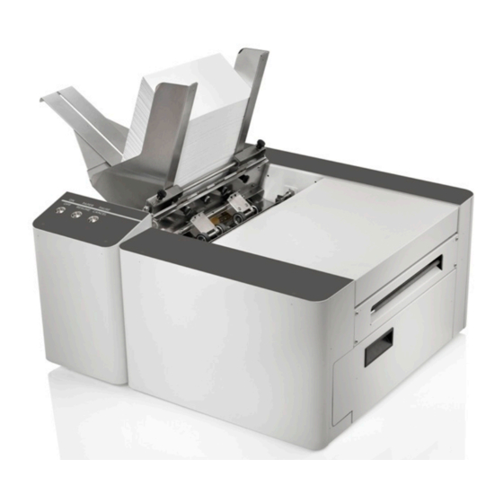
User Guide Digital Color Inkjet Printer MACH 5 For units with R15 Firmware... -
Page 2: Safety Precautions
To the best of our knowledge, that information is accurate in all respects. However, neither Neopost, Inc. nor any of its agents or employees shall be responsible for any inaccuracies contained herein. -
Page 3: Table Of Contents
TABLE OF CONTENTS Table of Contents SECTION 1 – GETTING ACQUAINTED ...................... 1 ..............................1 RONT ..............................2 ............................3 RINT NGINE ..........................4 EHIND THE /LED I ....................... 5 ONTROL ANEL UTTONS NDICATORS SECTION 2 – INSTALLING THE PRINTER ....................6 ........................... - Page 4 TABLE OF CONTENTS DIAGNOSTICS ............................49 SYSTEM SETTINGS ........................... 50 SCAN SENSORS ............................51 MAINTENANCE Drop-Down Menu ......................53 SERVICE Drop-Down Menu ........................55 PRINT Drop-Down Menu ........................56 ..............................56 RINTING Printhead Cartridge Conditioning ......................57 SECTION 4 – SOFTWARE SETUP INFORMATION ..................58 ........................
- Page 5 TABLE OF CONTENTS ........................96 RINTER AINTENANCE CHEDULE ........................ 97 REPARING RINTER FOR RANSPORT Local relocation ............................ 97 Remote relocation or shipping ......................97 SECTION 6 – TROUBLESHOOTING GUIDE .................... 100 : ..........................100 RINT UALITY SSUES Examples of Print Quality Issues (including possible causes and solutions) ........101 Air in Printhead Nozzle Area: ...........................
- Page 6 TABLE OF CONTENTS NOTES ______________________________________________________ ______________________________________________________ ______________________________________________________ ______________________________________________________ ______________________________________________________ ______________________________________________________ ______________________________________________________ ______________________________________________________ ______________________________________________________ ______________________________________________________ ______________________________________________________ ______________________________________________________ ______________________________________________________...
-
Page 7: Section 1 - Getting Acquainted
SECTION 1 GETTING ACQUAINTED Section 1 – Getting Acquainted Front View Control Panel – Provides printer controls. See "Control Panel Buttons/LED Indicators". Side Guide Locking Knob – Used to secure the position of the side guide. Rear Media Support Guide – Provides the proper angle to enhance paper feeding and separation. -
Page 8: Rear View
SECTION 1 GETTING ACQUAINTED Rear View Main Power Switch, Receptacle and Fuse – Plug in AC power cord here. Switch turns main power ON/OFF. Fuse provides over-current protection. Fuse rating: 2.5A, 250V, slow blow. CAUTION: Make sure power cord is disconnected from printer before checking/replacing fuse. WARNING: Press the ON/OFF Button, located on the control panel, to properly shut-down the print engine. -
Page 9: Print Engine Area
SECTION 1 GETTING ACQUAINTED Print Engine Area Print Engine with printhead cartridge installed and printhead latch closed. Antistatic Brush Assembly – Contains an antistatic brush that is used to help reduce static energy and remove paper dust from the media. This assembly also contains pressure rollers and fingers that help guide the paper into the print engine. -
Page 10: Behind The Ink Tank Door
SECTION 1 GETTING ACQUAINTED Behind the Ink Tank Door Ink Tank Securing Latches – Used to hold the Ink Tanks securely into the slots and against the electrical contacts within the print engine. NOTE: Please be sure that both sides, at the bottom part of the latch, are engaged. CAUTION! Before removing/installing Ink Tanks;... -
Page 11: Control Panel Buttons/Led Indicators
SECTION 1 GETTING ACQUAINTED Control Panel Buttons/LED Indicators The Control Panel has 3 buttons with LED indicators. ON/OFF – Press to power-up or power-down Print Engine. NOTE: The Main Power Switch must be ON to power-up the Print Engine. After pressing this button; it takes approximately 45 seconds for the print engine to power-up. -
Page 12: Section 2 - Installing The Printer
SECTION 2 INSTALLING THE PRINTER Section 2 – Installing the Printer Before using the printer the following must be done: • Transport Inspection. Upon delivery; inspect packaging and report any issues to the Carrier • Gather Tools • Choose a location for the Printer •... -
Page 13: Choosing The Location
SECTION 2 INSTALLING THE PRINTER Choosing the Location The printer should be placed on a sturdy, level, worktable or cabinet; at least 9 inches from any walls. Protect the printer from excessive heat, dust, and moisture – avoid placing it in direct sunlight. Work-Table Surface Must be Level IMPORTANT! Level the Table, to ensure that the Printer is level! The surface that the printer is placed upon must be level, front to back and side to side. -
Page 14: Unpacking
SECTION 2 INSTALLING THE PRINTER Unpacking Please refer to the unpacking sequence, shown below. NOTE: Packaging materials may vary slightly from what is shown below. Please save the packaging in a safe place, for possible future use. Two people will be required to safely lift the printer and place it onto a sturdy, level work table. IMPORTANT: WORK TABLE SURFACE MUST BE LEVEL! Save the Packaging for possible future use. -
Page 15: Accessory Box Contents
SECTION 2 INSTALLING THE PRINTER Accessory Box Contents Accessories Box Ink Tank Packaging The following items are included with your printer: Qty [Image Reference] Description [A] Ink Tanks (packed in foam molds) - Cyan, Magenta, Yellow, Black, Black [B] Printhead Cartridge and packaging [C] Rear Media Support Guide - thumb screw attached to printer [D] Service Station... -
Page 16: Removing The Cardboard Shipping Insert And Shipping Tape
SECTION 2 INSTALLING THE PRINTER Removing the cardboard Shipping Insert and Shipping Tape WARNING! To avoid possible damage to the printer; do NOT plug-in, or power-up, the printer until all shipping materials have been removed; as described below. 1. Open the Top Cover. 2. -
Page 17: Installing Media Guides & Rear Media Support
SECTION 2 INSTALLING THE PRINTER Installing Media Guides & Rear Media Support The screws needed to attach the side guides to the printer are located under the shipping tape in their respective positions. 1. Begin by installing the Media Registration Side Guide using the two screws [1] provided: 2. - Page 18 SECTION 2 INSTALLING THE PRINTER 3. Attach the Rear Media Support Guide using the Knob [3] and washer provided. Remove the knob and washer from the printer. Position the Rear Media Support Guide against the frame of the printer. The two outer holes in the guide fit over the socket head screws;...
-
Page 19: Connecting The Printer
SECTION 2 INSTALLING THE PRINTER Connecting the Printer Plugging in the Printer • Check to make sure the Main Power Switch [1] is in the OFF position. • Plug the Power Cord into the receptacle [1] at the rear of the Printer. •... -
Page 20: Connecting To The Computer
SECTION 2 INSTALLING THE PRINTER Connecting to the Computer The Printer connects to the computer through the USB port [2]. A Network port [3] is also provided; for connecting the printer to a network environment. IMPORTANT: Do NOT connect the printer to the computer, until prompted to do so, during the printer driver installation process. -
Page 21: Installing The Printer Software (Driver & Toolbox)
SECTION 2 INSTALLING THE PRINTER Installing the Printer Software (Driver & Toolbox) For the Printer software to operate properly check that the computer system meets the minimum requirements. See section titled “Minimum Computer System Requirements”, on previous page. NOTE: If you are updating the M Series Driver; please be sure to Uninstall the old Driver before installing the new Driver. - Page 22 SECTION 2 INSTALLING THE PRINTER 6. License Agreement. Check “I accept…” then click “Next>”. 7. Printer Connections. Click “Configure to print using USB”. Then click “Next>”. NOTE: Even if you plan to use the printer via an Ethernet Network Connection; your initial connection to the printer must be done via USB;...
- Page 23 SECTION 2 INSTALLING THE PRINTER 11. The “Finished software installation” window opens. Do not select (check) the Print Test Page as the Printer is not set up yet. If desired; you can select (check) the “Set this printer as the default printer” at this time. Then click Next>.
-
Page 24: Connecting The Printer Via Network (Ethernet Port)
SECTION 2 INSTALLING THE PRINTER Connecting the Printer via Network (Ethernet Port) 1. If you haven’t already done so; install the Printer Software (M Series Driver and Toolbox), via USB, by following the instructions in the previous section. Note: Initially the USB connection is needed in order to configure the printer’s internal network settings. - Page 25 SECTION 2 INSTALLING THE PRINTER 6. Open the Printer’s Toolbox. Select the “View” drop-down menu. Select “Service Menus”. The “Service Menus/“Diagnostics” window will open; displaying a lot of information about the printer. This information will include the Network Status and configuration settings.
-
Page 26: Installing The Ink Tanks
SECTION 2 INSTALLING THE PRINTER Installing the Ink Tanks The printer uses five Ink Tanks (two Black, one Cyan, one Magenta, and one Yellow). The Ink Tank is a delicate, precision device. Handle with extreme care to avoid damage. Ink Tank Anatomy The ink used in this system may be harmful if swallowed. -
Page 27: Procedure (Installing The Ink Tanks)
SECTION 2 INSTALLING THE PRINTER Procedure (Installing the Ink Tanks): This procedure assumes that you are installing Ink Tanks into a printer that doesn’t have any Ink Tanks installed. If you are replacing an empty Ink Tank, please refer to the “Replacing the Ink Tanks” section. Install the Ink Tanks as follows: 1. - Page 28 SECTION 2 INSTALLING THE PRINTER 4. Open the Ink Tank Door (hinged at bottom). 5. Open all three Ink Tank Securing Latches [A]. 6. Remove the new Ink Tank(s) from packaging. Ink Tank Door 7. Insert the new Ink Tanks (labels up) into their appropriate color slots [B].
- Page 29 SECTION 2 INSTALLING THE PRINTER 10. Verify Tank Recognition. Watch the Toolbox screen on your computer. You should see all the ink colors fill-in; if all the Ink Tanks are properly installed and recognized. New Tanks should read 99%. NOTE: If one or more ink color does not fill-in, after a few seconds, select “Replace Ink Tanks”...
-
Page 30: Installing The Printhead Cartridge
SECTION 2 INSTALLING THE PRINTER Installing the Printhead Cartridge The printer uses a single Memjet® printhead cartridge. The Printhead Cartridge is a delicate, precision device. Handle with extreme care to avoid damage and issues that could degrade print quality. ATTENTION If you experienced fuzzy print quality or an abrupt failure in a particular area of nozzles on the previous printhead, we recommend that you have the service station inspected/cleaned and the wiper roller replaced before installing the new printhead. - Page 31 SECTION 2 INSTALLING THE PRINTER CAUTION • Use electrostatic discharge (ESD) handling precautions. • Hold the Printhead Cartridge by the handles ONLY. • DO NOT touch the Ink Couplings, nozzle surface or electrical contacts. • DO NOT unpack the Printhead Cartridge until the Printer is ready for installation.
-
Page 32: Procedure (Installing The Printhead Cartridge)
SECTION 2 INSTALLING THE PRINTER Procedure (Installing the Printhead Cartridge) This procedure assumes that you are installing a Printhead Cartridge into a printer that does NOT have a Printhead Cartridge installed. If your printer already has a Printhead Cartridge installed, and you wish to replace the Printhead Cartridge;... - Page 33 SECTION 2 INSTALLING THE PRINTER 5. [A] Carefully remove the Printhead Cartridge from the foil packaging. Tear at notch or cut end with scissors. [B] Remove the protective plastic cover. Hold the Printhead by the handle and unclip the cover from the Printhead. [C] Remove protective strip from the Printhead Electrical Contacts.
- Page 34 SECTION 2 INSTALLING THE PRINTER 7. Open the Print Engine Clamshell. Use both hands to release both latches at the same time. 8. Using a lint-free cloth soaked with deionized or distilled water, wet the entire Printhead Nozzle area. Be liberal with the amount of water you leave behind on the nozzles (the thin dark line on bottom of printhead cartridge).
- Page 35 SECTION 2 INSTALLING THE PRINTER If you reach the end of the priming process and the printhead failed to prime (one or more of the ink tubes have not filled with ink): Release the printhead (using the Release Printhead feature from the Toolbox), Once the latch opens, carefully retract the latch fully.
-
Page 36: Envelope Printing Attachment Kit
SECTION 2 INSTALLING THE PRINTER Envelope Printing Attachment Kit The Envelope Printing Attachment Kit (42-900-55) is included with the printer. The printer is normally shipped with these items pre-installed. Kit Includes: • Head Media Guide (1) • Left-hand (large) PPS Spacer (1) •... - Page 37 SECTION 2 INSTALLING THE PRINTER 3. [A] & [B] Start with the Head Media Guide positioned as shown in “A”, on previous page. Note: The “Tab”, on the end of the Guide, fits over the front side of the metal “Support” plate. While lightly pressing up on the Guide;...
-
Page 38: Installing/Removing The Pps Spacers
SECTION 2 INSTALLING THE PRINTER Installing/Removing the PPS Spacers The PPS Spacers are designed to be used in conjunction with the Head Media Guide. These items are normally pre-installed in the printer. With the PPS spacers installed and the clamshell closed; the spacers make contact with both ends of the printhead cartridge, which pushes the Platen down a small amount. -
Page 39: Section 3 - Operating The Printer
SECTION 3 OPERATING THE PRINTER Section 3 – Operating the Printer Setting up the Feed The printer is equipped with four sheet separators, two side guides, a rear media support guide and two different sized media support wedges. When properly adjusted these items will separate and guide the media so that only one piece of media is fed into the print engine at a time. - Page 40 SECTION 3 OPERATING THE PRINTER 3. Loosen the locking screws, located behind the sheet separators, and raise the separators. Then tighten the locking screws to hold the separators in the up position. 4. Place a single piece of the media, to be run, under the separators.
- Page 41 SECTION 3 OPERATING THE PRINTER 7. Adjust the position of the Rear Media Support Guide, so that it is centered under the width of your media. This guide slides side to side. Tip: The Rear Media Support will slide, without loosening the knob.
-
Page 42: Printer Driver Properties
SECTION 3 OPERATING THE PRINTER Printer Driver Properties Valid for M Series Driver version R15 NOTE: The R15 Driver was developed for use with printer firmware version R15 20180130. They should be used as a set. If you try to use this Driver with other printer firmware versions, some of the Driver properties/features may not work. - Page 43 SECTION 3 OPERATING THE PRINTER o Back Page – Unavailable unless Printer is attached to “Duplex Unit”. Used to load a static (unchanging) “back page”, which will be stored and reprinted onto every piece that is fed into the Duplex Unit. o PC Capture –...
- Page 44 SECTION 3 OPERATING THE PRINTER Tip: When defining the width of a “custom media size” that measures between 8.5 and 9.5 inches wide; please set the width value to 8.5” (max print width of printer). Example: #10 Env (9.5”W x 4.13”H), feeding long-edge first. Set dimensions to 8.5”W x 4.2”H. Media Orientation Tip: When defining a “custom media size”;...
-
Page 45: Layout Tab
SECTION 3 OPERATING THE PRINTER • My Print Settings – Allows you to save or recall your custom Driver settings for various jobs. When you save or replace a “My Printer Settings” selection, all settings within the General, Layout and Color tabs are saved. -
Page 46: Color Tab
SECTION 3 OPERATING THE PRINTER keep the nozzles clear and hydrated. For irregular-shaped pieces (like an open envelope flap), the Paperpath Entry sensor may see the trailing edge too soon; causing the printer to purge (spray a line of ink) onto the flap. Tip: Optimally, this value should be set so the purge bar is positioned about 3 mm past the trailing edge of the media. -
Page 47: Import/Export Tab
SECTION 3 OPERATING THE PRINTER Import/Export Tab Import/Export is used to preserve any custom Media Sizes, Watermarks and Print Settings, you may have added/created for various jobs. • Watermarks – select to export/import • Media Sizes – select to export/import •... -
Page 48: Toolbox Features
SECTION 3 OPERATING THE PRINTER Toolbox Features Valid for printers with Firmware version R15 20180130 installed. Once the Printer Driver is installed, you can access the Printer’s Toolbox. You can check Printer status, monitor ink usage, perform diagnostic checks, print reports and run maintenance tasks on the Printer from your computer. -
Page 49: System Status View
SECTION 3 OPERATING THE PRINTER SYSTEM STATUS View This screen opens when you access the Toolbox. It provides information about the Printer. You can also access this view by selecting “View” then “System Status”. Status Indicator (located at top left corner) shows Printer activity as ONLINE, ERROR, MAINTENANCE, PRINTING or PAUSED. -
Page 50: User Interface View
SECTION 3 OPERATING THE PRINTER USER INTERFACE View SETUP Settings – Select “View”, then “User Interface” to open the User Interface menu. You can adjust automated service and cleaning intervals, adjust the feed mode, manually set the purge bar location and disable/enable items that may help to detect a paper jam/misfeed or eliminate false detection. - Page 51 SECTION 3 OPERATING THE PRINTER • Purge Bar Position (BoF)* – During normal operation, the Printhead spits (purges) a small amount of ink, into the gap between pieces. This is done to keep the nozzles clear and hydrated. The “Purge Bar Position” feature allows the operator to manually adjust the location where the “Purge Bar”...
- Page 52 SECTION 3 OPERATING THE PRINTER Display Language – Selects the language that the Toolbox information will be displayed. PLEASE BE SURE TO HIT "SUBMIT" AFTER CHANGING THIS SETTINGS Firmware Download – This feature is used to update the firmware in the printer. WARNING: This process should only be performed by a qualified support representative.
-
Page 53: Ink Usage View
SECTION 3 OPERATING THE PRINTER INK USAGE View • Ink Usage -- Select “View”, then “Ink Usage” to open the Ink Usage menu. o Printed Ink (µL) - These values are provided for the purpose of estimating the amount of ink usage for a particular print job. - Page 54 SECTION 3 OPERATING THE PRINTER • Job Cost Settings – The operator should enter the average amount paid for a single Ink Tank (estimator internally multiplies this figure by 5) and the amount paid for the printhead; then press “Submit”. These values are then used to calculate the “Estimated Page Cost”...
-
Page 55: Service Menus View
SECTION 3 OPERATING THE PRINTER SERVICE MENUS View Select “View”, then “Service Menus” to open. Diagnostics button. Click to check the status of the Printer. (See Diagnostics below.) System Settings button. Click to view, enter or change settings to connect Printer to your network. -
Page 56: System Settings
SECTION 3 OPERATING THE PRINTER SYSTEM SETTINGS Set up a network connection for the Printer. Set and configure Printer Date and Time. Note: To access and change these printer parameters; you must initially install the printer Driver via USB and connect to the printer via USB. -
Page 57: Scan Sensors
SECTION 3 OPERATING THE PRINTER • Date and Time – Enter or change the way the date and time will appear in the Printer Status section of the Toolbox screens. Enter or change Date and Time: 1. Select “View” and then select “Service Menus”. - Page 58 SECTION 3 OPERATING THE PRINTER Service Menus, Password For authorized service personnel only. Provides password-protected access to more advanced Printer Control menus. Type the Password and press Submit. The following “Service Menus” features will appear. • Printer Control Config • Commands Help •...
-
Page 59: Maintenance Drop-Down Menu
SECTION 3 OPERATING THE PRINTER MAINTENANCE Drop-Down Menu The printer automatically performs maintenance tasks to keep the printhead and ink system performing properly. The following buttons can be used, as needed, to provide supplemental maintenance. CAUTION: Over-use of these features can negatively affect print quality and printer performance. Note: The Memjet printhead contains 70,400 nozzles. - Page 60 SECTION 3 OPERATING THE PRINTER new printhead, it is recommended that the “wiper roller” be replaced whenever the printhead is replaced. Please contact your service preventative to have them perform this procedure. Do NOT use the above features to try to reduce “scuff marks” (black lines/streaks that are deposited on the media surface) and image smudging/smearing.
-
Page 61: Service Drop-Down Menu
SECTION 3 OPERATING THE PRINTER SERVICE Drop-Down Menu WARNING! These buttons should only be used by an experienced/trained user. Improper usage can cause damage to the system. These buttons control functions that require the machine to be “out of service”, for an extended time, while procedures are being performed. -
Page 62: Print Drop-Down Menu
SECTION 3 OPERATING THE PRINTER PRINT Drop-Down Menu Print various reports and Printer tests. Each printout displays information about the Printer. • Print Setup Page – Prints a test pattern used to align front and back sides of a page printed using a “Duplex Unit”. NOTE: Do not use to align border-lines with page edges. -
Page 63: Printhead Cartridge Conditioning
SECTION 3 OPERATING THE PRINTER Printhead Cartridge Conditioning When a printhead cartridge is installed, it is common for some residual ink accumulation to occur in certain areas within the print engine. There may also be some color contamination between ink channels and air bubbles trapped in the printhead. -
Page 64: Section 4 - Software Setup Information
SECTION 4 SOFTWARE SETUP INFORMATION Section 4 – Software Setup Information General Software Setup Info Note: The following information assumes you have the M Series Driver version R15.0 or higher installed on computer system and firmware version R15.0 or higher installed on printer. Do NOT exceed the Min or Max media specifications of the printer: •... -
Page 65: Adobe ® Acrobat/Reader Setup Tips
SECTION 4 SOFTWARE SETUP INFORMATION ® Adobe Acrobat/Reader Setup Tips In general, printing a PDF from Adobe Acrobat/Reader is straight-forward and easy. However there are a few limitations and quirks that you should be aware of. 1. Original PDF should be designed for the piece size and orientation you plan to use. Adobe Acrobat has some nice controls for changing orientation and adjusting the image size to fit the media size you select;... -
Page 66: Setting Up A Job In Bulk Mailer
SECTION 4 SOFTWARE SETUP INFORMATION ® Setting Up a Job in Bulk Mailer Tip: Since the “M Series Driver” was not developed by the manufacturer of “Bulk Mailer”, you will need to use the features within the “M Series Driver” to control print quality, orientation, etc. The following are descriptions of how to setup and print from Bulk Mailer 5.0 on #10 envelopes. - Page 67 SECTION 4 SOFTWARE SETUP INFORMATION 8. The “Envelope Options” window will open. Double-click on “New Envelope/Letter Layout” 9. An envelope design window will open. Type a name (example: Digital Color Printer #10 LEF) into the Layout Name window. Enter these values: Page Width: 8.5 in. Page Height: 4.13 in Click on OK and the envelope layout window will close.
- Page 68 SECTION 4 SOFTWARE SETUP INFORMATION 14. Add any additional items that you want printed to the “designer” screen. Drag and drop the items onto the layout, wherever you want them to be printed on the envelope. Click on Save. 15. Click on the "Go to Preview Mode" icon , located at the upper left-hand corner of the “designer”...
- Page 69 SECTION 4 SOFTWARE SETUP INFORMATION 19. Under Orientation select Portrait. Select your other desired choices Print Quality, Copies, etc. Then Click on OK to close this window. 20. In the “Mail Print Setup” window select “all pages” or the range of addresses you want to send to the printer.
-
Page 70: #10 Envelope, Feeding Short-Edge First
SECTION 4 SOFTWARE SETUP INFORMATION #10 Envelope, Feeding Short-Edge First 1. Open Bulk Mailer 5. 2. From the “Home” tab, select (double click) on the “mailing” of your choice. 3. Select the “Print Mail” tab (left side of screen). 4. From the “Print Mail” screen; double-click on the “Print Mail Wizard” which will guide you through the template (layout) setup process. - Page 71 SECTION 4 SOFTWARE SETUP INFORMATION 9. The “Address Block Options” window will open. Select your Address Block option (example: Add a basic address block with barcode) Select your Barcode Type option: POSTNET or Intelligent Mail. Click Next. 10. The “Summary” window will open. Under Template Options select “Preview labels based on settings”...
- Page 72 SECTION 4 SOFTWARE SETUP INFORMATION 14. Click on the printer icon , to open the "Mail Print Setup" dialog box. Make sure the “M Series Driver” is selected as the "Printer:”. 15. From the “Mail Print Setup” window; Click on the “Advanced Settings”...
-
Page 73: Section 5 - Maintenance
SECTION 5 MAINTENANCE Section 5 - Maintenance This section covers how to perform routine operator maintenance on the printer; including Ink Tank care, Printhead care, clearing paper jams, replacing Ink Tanks, replacing Printhead Cartridge, replacing sheet separators. If printer maintenance or service is needed beyond the scope of what is covered in this section; please contact your Dealer/Distributor for support. - Page 74 SECTION 5 MAINTENANCE 6. Clean the Ink Tank Level Prism [C] and QA Chip contacts [B] with a clean, dry, lint-free cloth. NOTE: You can dampen the cloth with distilled water to wipe the Prism, but Do NOT get the QA Chip contacts wet. Tip: A soft pencil eraser can also be used to lightly clean the QA Chip contacts [B].
-
Page 75: Replacing The Ink Tanks
SECTION 5 MAINTENANCE Replacing the Ink Tanks This procedure is almost identical to the procedure for installing new Ink Tanks into a new printer. The only difference are: - The Toolbox will display an “Ink_Out..” condition; once the ink in a particular Tank is depleted. - The empty Ink Tank(s) must be properly removed before installing the new Tank(s). - Page 76 SECTION 5 MAINTENANCE 3. Open the Ink Tank Door (hinged at bottom). 4. Unlock the Ink Tank Securing Latch(es) [A] that correspond to the “empty” Ink Tank positions. 5. Pull the empty Ink Tank(s) out of the Printer. 6. Remove the new Ink Tank(s) from their packaging.
-
Page 77: Ink Tank Storage & Shelf Life
SECTION 5 MAINTENANCE If an Ink Tank color does NOT fill-in and a question (?) mark or “Out” condition is displayed below the ink color; this indicates that the printer does not recognize the Ink Tank (Unable to communicate with QA Chip) or the ink level sensor doesn’t see any ink in the Tank. -
Page 78: Cleaning The Printhead Cartridge
SECTION 5 MAINTENANCE Cleaning the Printhead Cartridge The Printhead Cartridge is cleaned automatically; each time the printer is turned ON, periodically while the printer sits idle, before each job, periodically during the print job, and whenever a Printhead Maintenance routine is activated by the operator. From the M Series Driver: Three “…Clean Printhead”... -
Page 79: Manual Printhead Cleaning
SECTION 5 MAINTENANCE Manual Printhead Cleaning: NOTE: We recommend the use of nitrile powder-free gloves for this process. As a last resort, if running the built-in “... Clean Printhead” features don’t help improve print quality; the printhead cartridge can be cleaned manually. 1. -
Page 80: Replacing The Printhead Cartridge
SECTION 5 MAINTENANCE Replacing the Printhead Cartridge ATTENTION If you experienced fuzzy print quality or an abrupt failure in a particular area of nozzles on the previous printhead; we recommend that you have the service station inspected/cleaned and the wiper roller replaced, before installing the new printhead. If not; the chance of damage to the new printhead is greatly increased. -
Page 81: Printhead Storage & Shelf Life
SECTION 5 MAINTENANCE Printhead Storage & Shelf Life Properly stored, unopened, Printhead Cartridges have a shelf life of up to 1 year. ° Long Term: 14° F to 86° F (-10 C to 30° C Short Term: -11° F to 140° F (-25° C to 60° C) Storage Temperature Range: NOTE: Cumulative storage duration above 86°... -
Page 82: Inspecting & Cleaning The Lip Of The Capping Station
SECTION 5 MAINTENANCE Inspecting & Cleaning the Lip of the Capping Station The Capping Station (Cap) is part of the Service Station. When the printer is idle, the Service Station automatically caps the printhead to keep the nozzles hydrated. Excess ink can accumulate on the Lip of the Cap. This commonly occurs after a printhead cartridge is installed and the system is primed. -
Page 83: Inspecting The Wiper Roller
SECTION 5 MAINTENANCE Inspecting the Wiper Roller The Wiper Roller should be routinely inspected for signs of wear and debris. NOTICE! If you have not been trained or are uncomfortable performing this task, please contact your service support representative. Directions: 1. -
Page 84: Cleaning/Replacing Service Station Items
SECTION 5 MAINTENANCE Cleaning/Replacing Service Station Items The Service Station contains separate areas/devices that are used to perform the following tasks. • Cleaning. The Wiper Roller cleans the Printhead nozzles of excess ink and debris. • Printing/Purging. The Printing Platen acts as a base to support media during printing. It also contains a purging area;... - Page 85 SECTION 5 MAINTENANCE 3. Power-up the printer. 4. Open the Printer’s Toolbox. Open the “Service” drop-down menu. Select “Eject Service Station”. 5. Once the Service Station has ejected; power OFF the printer. Press the ON/OFF button once and wait about 45 seconds for the print engine to power off (all control panel light’s off).
-
Page 86: Cleaning The Service Station
SECTION 5 MAINTENANCE Cleaning the Service Station Caution: Please be sure that you are using proper cleaning techniques to clean items that come in contact with the printhead. Use only distilled or deionized water and lint free cloths. If you don’t follow this rule, you will introduce contamination into the printhead;... -
Page 87: Wiper Motor Assembly Removal And Cleaning
SECTION 5 MAINTENANCE Wiper Motor Assembly Removal and Cleaning Removal: 1. Disconnect (unplug) the wiper motor cable from the Service Station Printed Circuit Board [A]. 2. Remove the Printed Circuit Board [A] from the Service Station Tray. Carefully release clips to remove board. -
Page 88: Printing Platen And Capping Station Removal And Cleaning
SECTION 5 MAINTENANCE Printing Platen and Capping Station Removal and Cleaning Removal: Both of these items [A] simply lift out, for removal from the Service Station. Cleaning: 1. Rinse off ink using tap water. Tip: Make sure the valve, located on the bottom of the Capping Station, is clear of debris and working. -
Page 89: Installing The Service Station
SECTION 5 MAINTENANCE Installing the Service Station CAUTION THIS PROCESS MUST BE PERFORMED BY A QUALIFIED/TRAINED PERSON. NOTICE: Due to the technical nature of this procedure; it should only be performed by a qualified technical support person or someone that has been properly trained on this procedure. Please contact your technical support representative. - Page 90 SECTION 5 MAINTENANCE 6. Slide the Cable Securing Latch open on the Service Station Circuit Board; as shown below. Closed Opened 7. Locate the Ribbon Cable (from within the Service Station Slot). Insert the Ribbon Cable (blue side up) into the space under the Cable Securing Latch [1].
- Page 91 SECTION 5 MAINTENANCE 9. Carefully Open the Clamshell. 10. Look down through open area, in the Print Engine, to make sure the Service Station is aligned with the “Bar”; (Service Station Drive Shaft) as shown. If the Printhead Cartridge is not installed (has been removed), you can look down through the top of the Print-Engine, through the Printhead Cartridge opening.
-
Page 92: Still Experiencing Print Quality Issues
SECTION 5 MAINTENANCE 12. Turn the printer’s Main Power Switch ON; then press the control panel’s ON/OFF button. After printer initialization (~45 seconds) the Print Engine will automatically pull the Service Station the rest of the way in. NOTICE: If the Service Station should get jammed during this process (you hear motor stall noise or gear slipping noise);... -
Page 93: Inspecting/Replacing The Waste Ink Tray
SECTION 5 MAINTENANCE Inspecting/Replacing the Waste Ink Tray The Waste Ink Tray is filled with an absorbent material, used to capture the waste ink that drains from the Service Station. The Waste Ink Tray must be routinely removed, inspected and replaced as needed. 1. -
Page 94: Replacing The Sheet Separators
SECTION 5 MAINTENANCE Replacing the Sheet Separators The sheet separators (90-103-09) insure separation of the pieces as they are being fed. If you experience double sheet feeding and cannot adjust the separators to prevent this, replace the separators. Replacing the sheet separators is not difficult; however if you don’t feel confident about doing this yourself;... -
Page 95: Clearing Media Jams
SECTION 5 MAINTENANCE Clearing Media Jams When the printer detects a media feed problem, it will stop automatically. Depending on where the media stops; the message “PAPERPATH_PAPERJAM” or “PAPERPATH_FEED_TIMEOUT” will be displayed in the Toolbox. Once the jam has been removed from the system and the print engine is closed; press the PAPER/RESUME button on the control panel or press the Clear Error button in the Toolbox to continue printing. -
Page 96: Cleaning The Printer Body
SECTION 5 MAINTENANCE Cleaning the Printer Body WARNING THE PRINTER IS A PRECISION MACHINE THAT SHOULD BE CLEANED REGULARLY TO INSURE MANY YEARS OF SERVICE. BEFORE PERFORMING ANY MAINTENANCE, DISCONNECT THE MACHINE FROM ITS POWER SOURCE! DO NOT REMOVE SIDE COVERS! HIGH VOLTAGES PRESENT. Clean the Printer regularly to remove accumulated paper dust and ink. -
Page 97: Cleaning The Feed Rollers And Forwarding Rollers
SECTION 5 MAINTENANCE Cleaning the Feed Rollers and Forwarding Rollers The rubber Feed Rollers [A] and Forwarding Rollers [B] can become glazed with paper lint and ink from the media. They should be routinely cleaned with a mild household cleaner on a damp lint-free cloth. -
Page 98: Cleaning The Feed Sensor
SECTION 5 MAINTENANCE Cleaning the Feed Sensor The Feed Sensor is located between the media hopper and the print engine. It has a number of functions. - It is used to control the delivery of media to the print engine. - It is used to monitor the piece length. -
Page 99: Cleaning Other Items Inside The Print Engine
SECTION 5 MAINTENANCE Cleaning Other Items inside the Print Engine Areas in the Print Engine can become glazed with a buildup of dust, paper lint and accumulated ink and need to be cleaned regularly. This section covers the procedures for cleaning the following items. Grit Rollers (Media Transport Rollers) Media (Paperpath) Sensors Capping Station Lip... - Page 100 SECTION 5 MAINTENANCE 5. Use the procedures, as outlined below, to clean the following items. Grit Rollers [A]: Entry Mark Clean as needed using a small stiff-bristled brush (toothbrush), lightly moistened with distilled water. Do NOT use anything other than distilled water to clean the Rollers.
-
Page 101: Cleaning The Ink Revolver Couplings
SECTION 5 MAINTENANCE Cleaning the Ink Revolver Couplings This process should be performed just before a printhead cartridge is installed or re-installed; to remove contaminated/dry ink and other debris from the Ink Revolver Couplings. If this step is skipped; the printhead and or ink system could become contaminated resulting in an increase in print quality issues. -
Page 102: Printer Maintenance Schedule
SECTION 5 MAINTENANCE Printer Maintenance Schedule General, periodic maintenance is needed to keep the Printer in good working order. Many tasks can be performed by operators with basic supplies, no special tools needed. Other tasks should only be performed by trained service personnel. NOTE: High volume usage may require more frequent maintenance. MAINTENANCE TYPE COMPONENTS / TASKS DAILY... -
Page 103: Preparing Printer For Transport
SECTION 5 MAINTENANCE Preparing Printer for Transport Please use this procedure if you ever need to transport the printer to a new location or ship the printer. Please refer to the appropriate sections in the manual for details on installing/removing items from the printer. - Page 104 SECTION 5 MAINTENANCE 9. Remove the Printhead Cartridge and install protective covers on printhead. Be careful to avoid ink spills (drips) and stains during this process. Wipe the Printhead surface using a lint-free cloth dampened with distilled water. Store Printhead Cartridge in a sealed plastic bag. Try to remove most of the air from the bag before sealing it.
- Page 105 SECTION 5 MAINTENANCE NOTES ______________________________________________________ ______________________________________________________ ______________________________________________________ ______________________________________________________ ______________________________________________________ ______________________________________________________ ______________________________________________________ ______________________________________________________ ______________________________________________________ ______________________________________________________ ______________________________________________________ ______________________________________________________ ______________________________________________________...
-
Page 106: Section 6 - Troubleshooting Guide
SECTION 6 TROUBLESHOOTING Section 6 – Troubleshooting Guide The following troubleshooting guides are provided to assist you in solving any problems that might occur with the printer. We have tried to make them as complete as possible. The best advice we can offer is to make sure that the system is set up properly, plugged in, and that it has an adequate supply of ink before attempting to troubleshoot any problem. -
Page 107: Examples Of Print Quality Issues (Including Possible Causes And Solutions)
SECTION 6 TROUBLESHOOTING Examples of Print Quality Issues (including possible causes and solutions) The Memjet printhead cartridge contains 70,400 inkjet nozzles. These nozzles are divided into ten rows; two rows of nozzles for each color channel. Due to the extremely high number of nozzles; it is not uncommon for some nozzles to become contaminated, dehydrated or clogged. -
Page 108: Clogged/Damaged/Dead Nozzles
SECTION 6 TROUBLESHOOTING Clogged/Damaged/Dead Nozzles: Clogged/damaged/dead/ nozzles will normally show as thin, crisp, vertical lines of missing color. Multiple adjacent nozzles, with same issue, will show as wider, crisp, vertical lines of missing color. Clogged nozzles are normally due to Printhead nozzle dehydration or partial contamination. Damaged nozzles are normally due to improper cleaning or debris on wiper roller causing damage to head. -
Page 109: Color Mixing Issues
SECTION 6 TROUBLESHOOTING Color Mixing Issues: Color mixing will show as muddy, mottled or distorted (grainy) colors. Color mixing occurs when the ink from one color channel crosses over into another color channel. Since the inkjet nozzle rows are located very close to one another (ten rows of 7,040 nozzles, located within a 0.8 mm space), it is easy for partials or fibers to create bridges across color channels. -
Page 110: Scuff Marks And Smudging Issues
SECTION 6 TROUBLESHOOTING Scuff Marks and Smudging Issues: Scuff Marks occur when the media makes contact with an area of the printhead that has ink on it. Smudging occurs when the wet image, on the media, makes contact with something (most commonly the printhead) before it is dry. - Page 111 SECTION 6 TROUBLESHOOTING Smudging: Here is an example of “smudging” that occurred when an area of this page, with a wet image, made contact with the printhead. Note: There are also scuff marks in this example. As mentioned previously; smudging will increase the chance for scuff marks;...
-
Page 112: Fuzzy/Distorted Print
SECTION 6 TROUBLESHOOTING Fuzzy/Distorted Print Fuzzy/distorted print can occur for a number of reasons. Some common causes are listed/shown below. Problem: Poor original image quality (less than 300 dpi). Solution: Use high quality images. Problem: Choosing to print image in low resolution from software application. Solution: Set image to highest resolution possible from software application. -
Page 113: The Ink Tank(S)
SECTION 6 TROUBLESHOOTING The Ink Tank(s) Notice: To avoid problems caused by an Ink Channel (ink tube) running dry; the Ink Tank will be flagged as “Out” before it is totally dry. Therefore, it is common for a small amount of ink to be left within the Ink Tank when the “Out”... -
Page 114: The Printhead Cartridge
SECTION 6 TROUBLESHOOTING The Printhead Cartridge The Memjet printhead cartridge contains over 70,000 inkjet nozzles. These nozzles are divided into ten rows; two rows of nozzles for each color channel. Due to the very tiny size of each nozzle and the high number of nozzles;... - Page 115 SECTION 6 TROUBLESHOOTING The Printhead Cartridge (continued) CONDITION PROBLEM SOLUTION System will not prime the Printhead nozzles dry (air pulled Wet the Printhead nozzles using distilled water and a printhead after installing through nozzles; not allowing system to create vacuum) wet, lint-free cloth.
-
Page 116: The Printer
SECTION 6 TROUBLESHOOTING The Printer NOTICE: The printer will not print if any of the five ink tanks are empty or missing. Dots or Lines Printed on Media CONDITION PROBLEM SOLUTION You have exceeded Reduce paper width to 8.5” to avoid exceeding Multiple horizontal black lines are printed down the the maximum print... -
Page 117: Service Station Problems
SECTION 6 TROUBLESHOOTING Service Station Problems WARNING! Many of the issues related to Service Station function will require a qualified Service Person, or properly trained person, to diagnose and fix these issues. If you haven’t been properly trained or don’t feel comfortable performing these procedures;... -
Page 118: Interface Communication Problems
SECTION 6 TROUBLESHOOTING Interface Communication Problems CONDITION PROBLEM SOLUTION M Series Driver does not Wrong USB port selected in “M Verify that you are selecting the respond to printer being Series Driver”. appropriate USB port in the connected via USB. driver Ports Tab. -
Page 119: Feeding Problems
SECTION 6 TROUBLESHOOTING Feeding Problems CONDITION PROBLEM SOLUTION Media Support Wedge not used. The Media Support Wedge adds a slope to Intermittent feeding the stack and helps feeding. Side Guides set too tight to media. Readjust Side Guides. Dirty Feed Rollers. Clean the Feed Roller with distilled water and a cloth. -
Page 120: Errors And Warnings
SECTION 6 TROUBLESHOOTING Errors and Warnings Printer Alert Window Messages Messages sent from the driver and displayed on PC screen in a small popup window. MESSAGE SOLUTION Cleaning in Progress Wait until the message disappears. The printer will start printing your job once the cleaning process has completed. -
Page 121: Toolbox System Status Messages
SECTION 6 TROUBLESHOOTING Toolbox System Status Messages Use the Toolbox System Status screen to quickly determine and locate a problem in the Printers. Status Indicator ERROR shows in the red box. Printer Graphic Icon highlights which area of the Printer and system is affected. System Status information on the right displays the basic problem (in red). - Page 122 SECTION 6 TROUBLESHOOTING Toolbox System Status Messages (continued) SYSTEM STATUS PROBLEM SOLUTION Paper Jam Carefully open the Clamshell, remove PAPERPATH_PAPERJAM Media jam detected. jammed Media from printer and close Paperpath: Entry:Yes Exit:Yes the Clamshell. The System Status Printer has detected that message in should go away.
- Page 123 SECTION 6 TROUBLESHOOTING Toolbox System Status Messages (continued) SYSTEM STATUS PROBLEM SOLUTION DOOROPEN_FRONT Printer has detected that Verify that the “Clamshell” is closed the “Clamshell” is open. and securely latched at both sides. If closed; contact Service to check latch &...
- Page 124 SECTION 6 TROUBLESHOOTING Toolbox System Status Messages (continued) SYSTEM STATUS PROBLEM SOLUTION PRINTHEAD_UNPRIMED Printhead priming If just powered on, or Tanks/Printhead process has not complete just installed, wait a few minutes; error or has failed. may clear by itself. Ink delivery issue. Replace missing/empty Ink Tanks or Tanks that are reading less than 30%.
-
Page 125: Appendix A - Printer Specifications
APPENDICES Appendix A – Printer Specifications SPEED (color or mono) Page Printing 8.5” x 11” Up to 3,600 per hour (1600 x 800 dpi @12 ips) No. 10 Envelopes Up to 7,500 per hour (1600 x 800 dpi @ 12 ips) PRINT AREA 8.5"... -
Page 126: Appendix B - Supplies And Optional Hardware
APPENDICES Appendix B – Supplies and Optional Hardware The following supply items and optional hardware are available from your Dealer/Distributor: Supplies DESCRIPTION PART # Printhead Cartridge M5PRINT Wiper Roller 123-2480 Cyan Ink Tank (250 ml) M5C250 Magenta Ink Tank (250 ml) M5M250 Yellow Ink Tank (250 ml) M5Y250... -
Page 127: Appendix C - Quick Reference Info
APPENDICES Appendix C – Quick Reference Info Suggestion: Printout these quick reference sheets and attach to, or hang near, the printer. Control Panel Light Sequences – Quick Reference The lights (LED’s), on the three control panel buttons, indicate the status of the printer. -
Page 128: Driver Properties Printing Adjustments - Quick Reference
APPENDICES Driver Properties Printing Adjustments - Quick Reference These features are located under the Layout tab of the M Series Driver (R15) Left Adjustment - Moves the image area, left or right on the media. Range: -2.98mm left to +200.02mm right. Default = 0 Top Adjustment - Moves the image up or down on the media. - Page 129 INDEX Feed Setup ................33 Firmware Download ............. 46 Accessory Box Contents ............9 Fuse ................. 2, 119 Adjustable Media Side Guide ..........1, 9 Adobe Acrobat ..............59 Fuzzy Print ................106 Adobe Reader ................ 59 Air in Nozzles ..............101 Head Media Guide ..............
- Page 130 INDEX Paper/Resume Button, Control Panel ........5 Safety Precautions ..............2 Pause/Cancel Button, Control Panel ........5 Scan Sensors ................. 51 Power Scuff Marks ................. 104 Connection ................. 2 Service ................. 120 Cord ..................9 Service Life Main Power Switch ............2 Ink Tank ................
- Page 131 INDEX User Interface Menu .............. 44 View, Drop-Down Menu ............42 View Warning Messages .............. 114 Ink Usage................47 Waste Ink Tray ................ 4 Service Menus ..............49 Waste Ink Tray, Inspecting ........... 87 Systems Status ..............43 Wide Media Support Wedge ........... 9 User Interface ..............
- Page 132 Rev 05/23/2019 Copyright © Neopost 2019...
Need help?
Do you have a question about the RENA MACH 5 and is the answer not in the manual?
Questions and answers