Table of Contents
Advertisement
Advertisement
Table of Contents

Related Manuals for Neopost MACH 6


Summary of Contents for Neopost MACH 6
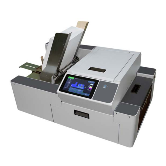
- Page 1 MACH 6 DIGITAL COLOR PRINTER SERVICE MANUAL Revised: 08-24-18 (Based on Firmware Version R1.3) PRELIMINARY Neopost Digital Print Group 3100 Horizon Drive, Suite 100 King of Prussia, PA 19406-2660 Phone: (610) 650-9170 www.neopostusa.com www.haslerinc.com www.renausa.com...
- Page 2 In addition, follow any specific occupational safety and health standards for your workplace or area. This manual is intended solely for the use and information of Neopost USA, its designated agents, customers, and their employees. The information in this guide was obtained from several different sources that are deemed reliable by all industry standards.
-
Page 3: Table Of Contents
TABLE OF CONTENTS Table of Contents SECTION 1 – Installing Printer Transport Inspection Tools Needed Choose a Location Operating Conditions Unpacking Contents of Packaging Removing Shipping Materials (Shipping Tape) Install Print Platen & Drip Tray Assembly ... - Page 4 TABLE OF CONTENTS General Disassembly and Assembly Replace 24V DC Power Supply Replace Interface PC Board Replace 5V DC Power Supply Replace Fast Internet Switch Replace Top Cover Switch Replace Clutch Replace Feed Drive Motor and Belt Replace Feeder Encoder ...
- Page 5 TABLE OF CONTENTS Replace Printhead Lever Latch Solenoid Inspect the Service Station Service Station Components Remove Capping Station Remove Wiper Roller Remove Wiper Roller Assembly Remove Service Station Base Plate Remove Service Station Sled Remove Service Station Positioning Belts ...
-
Page 7: Section 1 - Installing Printer
SECTION 1 INTRODUCTION SECTION 1 – Installing Printer Before using Printer: Transport Inspection. Upon delivery, inspect packaging and report any issues to the Carrier. Gather Tools Choose a location for Printer Unpack and verify Accessory Box contents ... -
Page 8: Choose A Location
SECTION 1 INTRODUCTION Choose a Location Place Printer on a sturdy level worktable or cabinet at least 9" from any walls. Open the Ink Tank Door and raise the Clamshell Assembly. Use the Bubble Gauge mounted on the Ink Station Frame (or a small level) placed on the Ink Station Frame to make sure Printer is level. -
Page 9: Contents Of Packaging
SECTION 1 INTRODUCTION Contents of Packaging Items included with the MACH 6 Printer. Rear Media Support Guide/Sled Assembly (Thumbscrew and mounting screws attached to Printer) Five Ink Tanks (packed in foam molds) – Cyan, Magenta, Yellow, Black, Black Printhead Cartridge (shown on top of packaging) -
Page 10: Removing Shipping Materials (Shipping Tape)
SECTION 1 INTRODUCTION Removing Shipping Materials (Shipping Tape) WARNING! To avoid possible damage to printer; do NOT plug-in, or power-up, printer until all shipping materials have been removed; as described below. NEED PICTURES of items to remove... -
Page 11: Install Print Platen & Drip Tray Assembly
SECTION 1 INTRODUCTION Install Print Platen & Drip Tray Assembly Select appropriate Platen and Install it into Drip Tray: Low Platen [1] (3 dots) is for media such as: heavy paper, envelopes, card stock, cardboard, chip-board, padded envelopes?? High Platen [2] (4 dots) is for thin, flexible media, such as: sheet paper up to and including 32 lb?? Make sure Platen is positioned onto both Alignment Pins [A], in Drip Tray, as shown below. - Page 12 SECTION 1 INTRODUCTION Install Print Platen & Drip Tray Assembly into Printer: 1. Open Ink Tank Door [A]. 2. Release, pull out on, Clamshell Latch [B], to release and raise Clamshell. 3. Insert tabs, at each end of Drip Tray, into frame slots [C] as shown below. CAUTION It is very important that you get the Drip Tray tabs into frame slots [C] or damage to the system may occur when you close Clamshell and or start using printer.
-
Page 13: Attach Media Side Guides And Rear Media Support Guide/Sled
SECTION 1 INTRODUCTION Attach Media Side Guides and Rear Media Support Guide/Sled 1. Attach Media Side Guide - Outer with two screws [1] (included). 2. Attach Media Side Guide - Inner with two screws [2] (included). 3. Attach Rear Media Support Guide/Sled using two screws (included) to secure it to the mounting holes on Center Plate [3]. - Page 14 SECTION 1 INTRODUCTION 05/31/18: New Wide Guide Wedge design coming? Narrow and Wide Media Support Wedges: Use the Narrow or Wide Media Support Wedges to accommodate very wide or very narrow media. 1. Fit the tabs on the Wedges into the appropriate slots on the Media Support Guide. See examples below. [A] Wide Guide installed.
-
Page 15: Connect Printer
SECTION 1 INTRODUCTION Connect Printer Plugging in Printer Plug power cord into receptacle [1] at rear of Printer. Internal power supply in Printer is rated 115 to 240VAC, 50/60 Hz. CAUTION DO NOT USE AN ADAPTER PLUGS OR EXTENSION CORDS TO CONNECT PRINTER TO WALL RECEPTACLE. -
Page 16: Section 2 - Troubleshooting
SECTION 2 TROUBLESHOOTING SECTION 2 – Troubleshooting This section is arranged by first the condition that might occur, and then by possible problems, their cause and recommended solutions. Power Problems CONDITION PROBLEM SOLUTION Power is ON, nothing No power to Printer. Check that power cord is plugged in. -
Page 17: Feeding Problems
SECTION 2 TROUBLESHOOTING Feeding Problems CONDITION PROBLEM SOLUTION Intermittent feeding Feed Ramp not used. Feed Ramp adds a slope to stack and helps feeding. Side Guides set improperly. Loosen Side Guides slightly. Dirty Feed Rollers. Clean Feed Roller with distilled water and a cloth. DO NOT use any solvents or detergents as they may damage Feed Rollers. -
Page 18: Memjet Printhead
SECTION 2 TROUBLESHOOTING Memjet Printhead CONDITION PROBLEM SOLUTION Missing parts of letters or Air and bubbles blocking Clean the Printhead using recirculation, text. nozzles. priming or cycles of depriming and priming found on the Printer Touchscreen or in the Printer Toolbox. Printhead is dry. -
Page 19: Printing Problems
SECTION 2 TROUBLESHOOTING Printing Problems CONDITION PROBLEM SOLUTION Ink Tank installed, no Ink Level Ink Tank contacts dirty, Remove Ink Tank(s). Clean prism and indication in Toolbox preventing Printer/Ink Tank QA Chip contacts, see Maintenance, communication. Cleaning Ink Tank Contacts. Extra lines;... -
Page 20: Errors And Warnings
SECTION 2 TROUBLESHOOTING Errors and Warnings Printer Alert Window Messages Messages sent from Driver and displayed on PC screen in a small popup window. MESSAGE SOLUTION Wait until message disappears. Printer will start printing your job once cleaning Cleaning in Progress process is complete. - Page 21 SECTION 2 TROUBLESHOOTING Toolbox System Status Messages (Valid for printers with firmware version R?? or higher installed.) Use the Touchscreen or Toolbox screen to quickly determine and locate a problem in the Printer. Status Indicator shows ERROR shows in red box. Printer Graphic Icon highlights Printer and system affected. The System Status information on the right displays the basic problem (in red).
- Page 22 SECTION 2 TROUBLESHOOTING Toolbox System Status Messages (Continued) SYSTEM STATUS SOURCE SOLUTION System Status: Media is not moving Check/clean Transport Rollers. DATA_PATH_UNDERRUN from Entry Sensor to Check/clean Sensors. Exit Sensor within a Try changing orientation setting in specified time. software/driver or setting a different Possible issue with media size.
- Page 23 SECTION 2 TROUBLESHOOTING Toolbox System Status Messages (Continued) SYSTEM STATUS SOURCE SOLUTION System Status: TILT_ERROR Printer is not level*. Make sure that the Printer is placed on a level surface. Failure to do so may Printer’s electronics result in severe ink mixing and cause have detected that an inaccurate ink level reading in Ink Print Engine is too far...
- Page 24 SECTION 2 TROUBLESHOOTING Toolbox System Status Messages (Continued) SYSTEM STATUS SOURCE SOLUTION System Status: PRINTHEAD_MISSINGQA Printhead missing and Check Printer Graphic and Ink Levels one or more of Ink displaying “?”. Tanks are missing, Install Printhead. When this error occurs, Install Ink Tanks.
- Page 25 SECTION 2 TROUBLESHOOTING Toolbox System Status Messages (Continued) SYSTEM STATUS SOURCE SOLUTION System Status: WIPER OVERTEMP Wiper Motor is Wait for Wiper Motor to cool down, overheated due to Printer will automatically resume performing a Wiper operation. NOTE: If running a number Transfer (removing of short jobs or jobs on smaller media, reset Mid-Job Servicing interval to a...
-
Page 26: Jams In Printer
SECTION 2 TROUBLESHOOTING Jams in Printer If a jam occurs, STOP the Printer. Some possible causes for jamming are: 1. Feeding more than one piece of media (double-feeding). 2. Damaged media, such as dog-eared (turned down corners). 3. Media that is not stiff enough may not be usable. Media that meets Postal stiffness requirements for automated feeding is acceptable in Printer. -
Page 27: Section 3 - Touchsreen And Toolbox Operation
SECTION 3 TOUCHSCREEN AND TOOLBOX OPERATION SECTION 3 – Touchsreen and Toolbox Operation Tap the screen to view the Printer Touchscreen. [A] System Status Indicator (at top of screen) [B] Drop-Down Menu Options (at top of screen) [C] Check Printer Status (across middle of screen) [D] Five often-used control buttons (at bottom of screen) Drop-Down Menu Options The Menu drop-down gives you five selections:... - Page 28 SECTION 3 TOUCHSCREEN AND TOOLBOX OPERATION System Test NOTE: These tests should only be performed by authorized service personnel. System Test allows testing individual or all Printer systems listed to check that they are operating within specifications. It also allows service people to check the Printer after servicing or replacing parts, particularly belts.
- Page 29 SECTION 3 TOUCHSCREEN AND TOOLBOX OPERATION Results: Error in red – There is a problem with that system (For example, a disconnected wire harness, or worn or broken component.) Red number – There is an issue with that system or component. It may be a loose connection or indication that the component is about to fail.
-
Page 30: Using Printer Toolbox
SECTION 3 TOUCHSCREEN AND TOOLBOX OPERATION Using Printer Toolbox To open Toolbox (on a computer): Open Start Menu; then click on Toolbox, select S Series Driver: NOTE: Conventional Screens: Use your cursor. Touchscreens: Tap buttons or selections or use your cursor. [A] System Status Indicator and Drop-Down Menu Options (at top of screen). - Page 31 SECTION 3 TOUCHSCREEN AND TOOLBOX OPERATION Service Menus Clicking Service Menus opens the Service Menus (Diagnostics) screen and service menu buttons. Diagnostics button. Click to check the status of the Printer. (See Diagnostics below.) System Settings button. Click to view, enter or change settings to connect Printer to your network.
- Page 32 SECTION 3 TOUCHSCREEN AND TOOLBOX OPERATION System Settings Set up a network connection for the Printer. You can also configure and set the Printer Date and Time, set the Debug Log Level and Screensaver sleep timeout. Network Settings – Permits you to view, enter or change settings to connect the Printer to your network. Network Connection Set Up: 1.
- Page 33 SECTION 3 TOUCHSCREEN AND TOOLBOX OPERATION Date and Time – Enter or change the way the date and time will appear in the Printer Status section of the Toolbox screens. To enter or change Date and Time: 1. From the Toolbox, select “View” drop-down menu, click “Service Menus”, then click “System Settings”.
- Page 34 SECTION 3 TOUCHSCREEN AND TOOLBOX OPERATION Screensaver – Set the amount of time the Touchscreen will remain idle before automatically going to Sleep Mode. 1. From the Toolbox, select “View” drop-down menu, click “Service Menus”, and then click “System Settings”. 2.
- Page 35 SECTION 3 TOUCHSCREEN AND TOOLBOX OPERATION Debug Logs Access, print or send activity logs for the Printer and for jobs run on the Printer. These files are valuable for diagnosing and servicing problems. All – Shows all log files available. Debug –...
- Page 36 SECTION 3 TOUCHSCREEN AND TOOLBOX OPERATION Scan Sensors Provides status updates and an activity log on the Sensors located throughout the Printer. (See chart at below.) Click “Stop” button to stop scanning or click out of “Scan Sensors”. SENSOR DESCRIPTION Feeder Sensor 08/22/18: Entry Sensor...
- Page 37 SECTION 3 TOUCHSCREEN AND TOOLBOX OPERATION C Out K1 Out K2 Out...
-
Page 38: Advanced Service Menus
SECTION 3 TOUCHSCREEN AND TOOLBOX OPERATION Advanced Service Menus Opening “Service Menus” screen, then entering the password under Service Menus, opens the Advanced Service Menus. Now you can use the following options: “Printer Control Config,” “Commands Help,” and “Exit Service Menus.” Printer Control Configuration Screen: Used to help in troubleshooting or servicing the Printer by adjusting factory settings to... - Page 39 SECTION 3 TOUCHSCREEN AND TOOLBOX OPERATION Printer Commands Help Screen: Provides a list and descriptions of available EWS service commands. Clicking “Exit Service Menus” closes Service Menu options and returns to User Interface screen.
-
Page 40: Update Firmware
SECTION 3 TOUCHSCREEN AND TOOLBOX OPERATION Update Firmware Get latest version of firmware for your Printer. NOTE: Use this procedure to update firmware AFTER you have updated Printer Driver. Printer Driver update procedure is included with an “Update Package” which includes both updated Printer Drivers and firmware updates). -
Page 41: Section 4 - Adjustments
SECTION 4 ADJUSTMENTS SECTION 4 – Adjustments Feed Drive Motor Belt Tension Adjustment 1. Remove Non-Operator Side Cover. 2. Loosen (2) mounting screws and washers [A]. 3. Move Motor Assembly up or down to tension the Belt [B]. When properly tensioned, there should be about 1/8" of deflection in the Belt. -
Page 42: Paper Path Rollers Belt Tension Adjustment
SECTION 4 ADJUSTMENTS Paper Path Rollers Belt Tension Adjustment 1. Remove Non-Operator Side Cover. 2. Remove Paper Path Plate Assembly. 3. Loosen Idler/TensionPulley screw and washer [A] (located on Non-Operator side). Move Idler Pulley Assembly up or down to tension the Belt [B]. When properly tensioned, there should be about 1/8"... -
Page 43: Printhead Lift Assembly Belts Tension Adjustment
SECTION 4 ADJUSTMENTS Printhead Lift Assembly Belts Tension Adjustment NOTE: To ensure proper Printer operation, it is recommended that you check/adjust both Printhead Lift Assembly Belts at the same time. 1. Remove the Control Panel Cover. Disconnect the Touchscreen Ethernet Cable if necessary. -
Page 44: Service Station Motor Drive Belt Tension Adjustment
SECTION 4 ADJUSTMENTS Service Station Motor Drive Belt Tension Adjustment 1. Remove the Top Assembly Rear Cover. 2. Open the Top Cover. 3. Loosen (2) screws [A] securing the Service Station Motor Assembly to the Top Assembly Frame. 4. Move Idler Pulley Assembly up or down to tension the Motor Drive Belt [B]. - Page 45 SECTION 4 ADJUSTMENTS Non-Operator Side: 1. Loosen the Service Station Belt Tensioner Pulley [A] (1 screw). NOTE: This will release tension on both the Service Station Motor Drive Belt and the Positioning Belt. When adjusting this Belt you will need to recheck and retension the Service Station Motor Drive Belt.
-
Page 46: Media Thickness Adjustment Lift Motor Drive Belt Tension Adjustment
SECTION 4 ADJUSTMENTS Media Thickness Adjustment Lift Motor Drive Belt Tension Adjustment 1. Open the Ink Tank Door. Raise the Top Assembly. 2. Remove the Left-hand Operator Side Cover. 3. Loosen (2) screws [A] securing the Media Thickness Lift Motor to the Printer Side Frame. -
Page 47: Testing Belt Tension
SECTION 4 ADJUSTMENTS Testing Belt Tension Verify that belts are properly tensioned by using the System Test (available through the Touchscreen or Toolbox). Before running the System Test, make sure that the Printer is powered up, all Printer systems are connected and functioning, and the paperpath is clear of obstructions. - Page 48 SECTION 4 ADJUSTMENTS Results: Error in red – There is a problem with that system (For example, a disconnected wire harness, or worn or broken component.) Red number – There is an issue with that system or component. It may be a loose connection or indication that the component is about to fail.
-
Page 49: Section 5 - Disassembly/Assembly Procedures
SECTION 5 DISASSEMBLY AND ASSEMBLY SECTION 5 – Disassembly/Assembly Procedures Printer Basic Disassembly Turn off Power Disconnect Power Cord Disconnect Interface Cable Service Disassembly Procedures WARNING! THE FOLLOWING DISASSEMBLY SHOULD ONLY BE DONE BY A QUALIFIED, TRAINED SERVICE REPRESENTATIVE. WARNING! ALWAYS POWER DOWN PRINTER BEFORE CONNECTING OR DISCONNECTING ANY WIRING HARNESSES OR CABLE CONNECTIONS TO... -
Page 50: Printer Covers
SECTION 5 DISASSEMBLY AND ASSEMBLY Printer Covers Operator Side Covers Left-Hand Cover: 1. Raise Top Assembly and open Ink Tank Door. Remove (2) screws at top [A] and bottom [B] of Left-hand Cover. 2. Reassemble in reverse order. Right-Hand Cover: 1. -
Page 51: Control Panel
SECTION 5 DISASSEMBLY AND ASSEMBLY Control Panel 1. Open the Top Cover and Ink Tank Door. 2. Remove (2) screws at top [A] and (2) screws from bottom [B] of Control Panel. 3. Carefully lift the Control Panel Assembly off of the Printer. NOTE: Be careful of stretching or breaking wiring harnesses, cables and connectors. -
Page 52: Ink Tank Door
SECTION 5 DISASSEMBLY AND ASSEMBLY Ink Tank Door 1. Open the Ink Tank Door. 2. Carefully unhook (2) springs [A] from the Ink Tank Door studs. 3. Remove (1) mounting screw from each side [B]. Remove Door. 4. Reassemble in reverse order. - Page 53 SECTION 5 DISASSEMBLY AND ASSEMBLY Major Components under Non-Operator Side Covers 1. Media Thickness Lift Assembly 14. Clutch Assembly 2. Exit Fan Wire Harness 15. Feeder Encoder Assembly 3. Printhead Lifter Sensor 16. Feed Motor 4. Top Assembly 17. 24V DC Power Supply 5.
- Page 54 SECTION 5 DISASSEMBLY AND ASSEMBLY Major Components under Exit End Cover 1. Exit Media Conveyor 2. Exit Media Sensor 3. Ink Station 4. Media Thickness Adjustment Motor 5. DPCA 2 6. Multiplex (MX) PCB 7. DPCA 1...
-
Page 55: General Disassembly And Assembly
SECTION 5 DISASSEMBLY AND ASSEMBLY General Disassembly and Assembly Replace 24V DC Power Supply 1. Remove Non-Operator Side Cover. 2. Remove (4) mounting screws and washer [A] securing the Power Supply (located under the Printer Base). NOTE: Before disconnecting Power Supply, note where wires are connected, then disconnect wires. -
Page 56: Replace Interface Pc Board
SECTION 5 DISASSEMBLY AND ASSEMBLY Replace Interface PC Board CAUTION MAKE SURE THAT YOU ARE PROPERLY GROUNDED BEFORE HANDLING PC BOARD. STATIC ELECTRICITY CAN DAMAGE BOARD. 1. Remove Non-Operator Side Cover. 2. Disconnect PC Board power cord [1] from the J2 terminal on PC Board. -
Page 57: Replace Fast Internet Switch
SECTION 5 DISASSEMBLY AND ASSEMBLY Replace Fast Internet Switch 1. Remove Non-Operator Side Cover. 2. Switch [A] (located behind the Interface PC Board and 5V DC Power Supply) is secured with hook & loop tape. Carefully pull the Switch away from the Printer Side Frame. -
Page 58: Replace Clutch
SECTION 5 DISASSEMBLY AND ASSEMBLY Replace Clutch 1. Remove the Non-Operator Side Cover. 2. Disconnect the Clutch wire harness from the Clutch extension wire harness at the connector [A]. 3. Push the Clutch in toward the Pulley to access retaining pin [B]. -
Page 59: Replace Feed Drive Motor And Belt
SECTION 5 DISASSEMBLY AND ASSEMBLY Replace Feed Drive Motor and Belt 1. Remove the Non-Operator Side Cover. 2. To remove the Feed Drive Belt: [A] Disconnect the Clutch wire harness at the connector. [B] Loosen (2) motor mount screws. Slide motor in slots to release Belt tension. -
Page 60: Replace Paper Path Drive Motor
SECTION 5 DISASSEMBLY AND ASSEMBLY Replace Paper Path Drive Motor 1. Remove Non-Operator Side Cover. 2. Remove (2) mounting screws and washers [A]. 3. Disengage drive belt [B] from pulleys. 4. Slowly pull Motor Assembly through the opening in the Side Frame. Disconnect the POS red and NEG black wire harnesses [C] from the Motor Assembly. -
Page 61: Replace Peristaltic Pump
SECTION 5 DISASSEMBLY AND ASSEMBLY Replace Peristaltic Pump 1. Before powering the Printer OFF, open “Service” from the “Menu” drop-down. Tap “System Deprime”. Power Printer OFF. 2. Remove Non-Operator Side Cover. 3. Open Top Cover. Remove (2) screws [A] securing the Pump Assembly to the Top Assembly Frame. -
Page 62: Replace Printhead Home Sensor
SECTION 5 DISASSEMBLY AND ASSEMBLY Replace Printhead Home Sensor 1. Remove Non-Operator Side Cover. 2. Disconnect the Sensor wire harness from MPCA terminal (J750) [A]. Carefully cut wire ties as necessary to release the wire harness. NOTE: Make a note of how the wire harness is routed and wire tied through the Printer for easier installation. -
Page 63: Replace Main Pc Board (Mpca)
SECTION 5 DISASSEMBLY AND ASSEMBLY Replace Main PC Board (MPCA) CAUTION MAKE SURE THAT YOU ARE PROPERLY GROUNDED BEFORE HANDLING PC BOARD. STATIC ELECTRICITY CAN DAMAGE BOARD. 1. Remove Non-Operator Side Cover. 2. Unplug PC Board power cord [1] from the P1000 terminal on the MPCA Board. 3. -
Page 64: Replace Dpca Boards
SECTION 5 DISASSEMBLY AND ASSEMBLY Replace DPCA Boards TO REMOVE INDIVIDUAL DPCA BOARDS: 1. Remove Exit Cover (4 screws). 2. Disconnect wire harnesses from terminals on DPCA 1 [A] and/or DPCA-2 [B]. NOTE: Wire harnesses are labelled for easy reconnection. DPCA-1 wire harnesses are labelled (-1) and DPCA-2 wire harnesses are labelled (-2). -
Page 65: Replace Exit Cover And Exit Wheel Assembly
SECTION 5 DISASSEMBLY AND ASSEMBLY Replace Exit Cover and Exit Wheel Assembly 1. Before powering off the Printer, position the Media Thickness adjustment to its lowest setting. 2. Remove Non-Operator Side Cover and Right-hand Operator Side Cover. 3. Open Top Assembly and Exit Conveyor Cover. 4. -
Page 66: Replace Conveyor Assembly
SECTION 5 DISASSEMBLY AND ASSEMBLY Replace Conveyor Assembly 1. Remove Right-hand Operator Side Cover, Non-Operator Side Cover and Exit Cover. 2. Remove the Exit Wheels Assembly. 3. Open the Ink Tank Door. 4. Disconnect Media Exit Sensor at the wire harness connector [A]. -
Page 67: Replace Media Exit Sensor
SECTION 5 DISASSEMBLY AND ASSEMBLY Replace Media Exit Sensor 1. Remove Right-hand Operator Side Cover, Non-Operator Side Cover and Exit Cover. 2. Open the Ink Tank Door. 3. Disconnect the Media Exit Sensor at the wire harness connector [A]. Remove the Exit Conveyor Assembly. -
Page 68: Replace Media Path Encoder Assembly
SECTION 5 DISASSEMBLY AND ASSEMBLY Replace Media Path Encoder Assembly 1. Open Top Assembly. 2. Remove (2) screws [A] securing Encoder Cover to the Side Frame. 3. Disconnect wire harness [B] from Encoder Sensor Assembly PC Board. 4. Remove (2) screws [C] securing Encoder Sensor Assembly to Side Frame and pull away from Encoder Wheel. -
Page 69: Replace Top Assembly Switch
SECTION 5 DISASSEMBLY AND ASSEMBLY Replace Top Assembly Switch 1. Remove Left-hand Operator Side Cover. 2. Disconnect Top Assembly Switch (SW) Wire Harness [A] at the connector. 3. Remove (1) screw [B] securing Switch Assembly to the Side Frame. Remove Switch Assembly. 4. -
Page 70: Replace Media Thickness Motor
SECTION 5 DISASSEMBLY AND ASSEMBLY Replace Media Thickness Motor 1. Remove Right-hand Operator Side Cover, Non-Operator Side Cover and Exit Cover. 2. Open the Ink Tank Door. 3. Disconnect the Media Thickness Motor to DPCA-2 wire harnesses J17A and J18A [A] from the DPCA-2 terminals. 4. -
Page 71: Replace Media Thickness Home Sensor
SECTION 5 DISASSEMBLY AND ASSEMBLY Replace Media Thickness Home Sensor 1. Remove Right-hand Operator Side Cover. 2. Open the Ink Tank Door. 3. Disconnect the Media Thickness Home Sensor at the wire harness connector [A]. 4. Remove (2) screws [B] securing the Sensor Bracket Assembly to the Side Frame. -
Page 72: Replace Center Plate Assembly
SECTION 5 DISASSEMBLY AND ASSEMBLY Replace Center Plate Assembly 1. Remove Left-hand Operator Side Cover and Non-Operator Side Cover. (You may also have to remove the Printer Ports Bracket.) 2. Remove (10) mounting screws [A] (5 screws per side). 3. Install in reverse order. -
Page 73: Replace Paper Path Plate
SECTION 5 DISASSEMBLY AND ASSEMBLY Replace Paper Path Plate 1. Remove Right-hand Operator Side Cover and Non-Operator Side Cover. 2. Open the Ink Tank Door and open (or remove?) the Top Assembly. 3. Remove (6) mounting screws [A] (3 per side). 4. -
Page 74: Replace Feed Roller Assemblies
SECTION 5 DISASSEMBLY AND ASSEMBLY Replace Feed Roller Assemblies Follow the steps below to remove the Rear [1], Middle [2] and Front [3] Feed Roller Assemblies: 1. Remove the Left Operator Side Cover and the Non-Operator Side Cover. 2. Remove the Separator Assembly. 3. -
Page 75: Replace Pull-Out Shaft Roller Assembly
SECTION 5 DISASSEMBLY AND ASSEMBLY Replace Pull-Out Shaft Roller Assembly Follow the steps below to remove the Pull-Out Shaft Roller Assembly [1]: 1. Remove the Left Operator Side Cover and the Non-Operator Side Cover. 2. Open the Ink Tank Door and raise the Top Assembly. -
Page 76: Replace Paper Path Rollers
SECTION 5 DISASSEMBLY AND ASSEMBLY Replace Paper Path Rollers The Paper Path Rollers include the [1] Delivery, [2] Input Print and [3] Output Print Rollers. 1. Remove Non-Operator Side Cover. 2. Remove Paper Path Plate Assembly and Ink Drip Tray. Remove the Delivery Roller: 1. - Page 77 SECTION 5 DISASSEMBLY AND ASSEMBLY Remove the Output Print Roller: 1. Loosen Idler/Tensioner Roller [A] mounting screw (located on Non- Operator side) to release tension on the Paper Path Drive Belt. 2. Remove the Encoder Guard and Paper Path Encoder Wheel [D]. Remove the Encoder Shaft Extension [E].
-
Page 78: Replace Paper Path Drive Motor And Roller Belts
SECTION 5 DISASSEMBLY AND ASSEMBLY Replace Paper Path Drive Motor and Roller Belts IMPORTANT: Before turning Printer power OFF, raise the Media Thickness Adjustment Assembly to its highest position to align access holes with fasteners. Turn Printer OFF. 1. Remove Non- Operator Side Cover. -
Page 79: Remove Media Thickness Adjusting Assembly
SECTION 5 DISASSEMBLY AND ASSEMBLY Remove Media Thickness Adjusting Assembly 1. Remove the Right- hand Operator Side Cover. 2. Remove the Non- Operator Side Cover and the Top Assembly Rear Cover. 3. Open the Ink Tank Door. Raise the Top Assembly. - Page 80 SECTION 5 DISASSEMBLY AND ASSEMBLY Non-Operator Side: 1. Unhook (2) Springs [H] from the Upper Mounts on the Printer Side Frame. 2. Remove (4) screws [I] securing Top Assembly Hinge Pins to the Media Thickness Lift Frame. 3. Remove (2) screws [J] securing the Hold-down Wheels Support to the Lift Frame.
-
Page 81: Ink Station Disassembly
SECTION 5 DISASSEMBLY AND ASSEMBLY Ink Station Disassembly Remove Ink Station Removing the Ink Station allows easy access to all of the components. Make sure you have run System Deprime before powering the Printer OFF. NOTE: Be careful of ink drips when disconnecting Ink Hoses. 1. - Page 82 SECTION 5 DISASSEMBLY AND ASSEMBLY 9. Remove (3) mounting screws and washers securing the Ink Station to the Printer Base [H]. 10. Remove (2) screws securing the Ink Station to the Operator Side Frame [I]. 11. Carefully slide the Ink Station out of the Printer.
-
Page 83: Ink Station Components
SECTION 5 DISASSEMBLY AND ASSEMBLY Ink Station Components 1. Buffer Boxes (x3) 2. QA Chip Assembly (x3) 3. Ink Tank Level PCA 4. Peristaltic Pump (Waste Pump for Service Station) 5. Dual Pinch Valve Replace Buffer Boxes (3 per Printer) 1. -
Page 84: Replace Qa Chip Assembly (3 Per Printer)
SECTION 5 DISASSEMBLY AND ASSEMBLY Replace QA Chip Assembly (3 per Printer) 1. Each QA Chip Assembly [A] is held in place by (1) screw accessed through the center of Chip Assembly. Carefully disconnect the wire harness(es) [B] from the Printed Circuit Boards. -
Page 85: Replace Peristaltic Waste Pump Assembly
SECTION 5 DISASSEMBLY AND ASSEMBLY Replace Peristaltic Waste Pump Assembly Remove old Pump Assembly: 1. Remove (2) screws [A] that attach the Pump Assembly to the Ink Station Base. (Located under the Ink Station Base.) 2. Disconnect wire harness connector [B] from Pump Motor Circuit Board terminal. -
Page 86: Replace Dual Pinch Valve Assembly
SECTION 5 DISASSEMBLY AND ASSEMBLY Replace Dual Pinch Valve Assembly Remove old Valve Assembly: 1. Remove (2) screws [A] that attach the Valve Assembly to the Ink Station Base. (Located under Ink Station Base.) 2. Unplug (2) wire harness connectors [B] from the Valve Assembly. -
Page 87: Clean Dual Pinch Valve Sensors
SECTION 5 DISASSEMBLY AND ASSEMBLY Clean Dual Pinch Valve Sensors If “Valve: Unknown” icon (?) appears for other than a few seconds in “Valve:” section of Printer Icon on the Touchscreen or in the Toolbox, it may indicate that DPV Sensors are blocked. Ink Station must be removed for this procedure. -
Page 88: Replace Dual Pinch Valve Sensor Pc Board
SECTION 5 DISASSEMBLY AND ASSEMBLY Replace Dual Pinch Valve Sensor PC Board To perform this operation you will need a Dual Pinch Valve Wrench (#42-301-08). The Pinch Valve Wrench holds the spring-loaded Pinch Valve Shaft in place when replacing the PC Board. Remove Dual Pinch Valve Assembly: 1. - Page 89 SECTION 5 DISASSEMBLY AND ASSEMBLY Replace Pinch Valve Sensor PC Board 1. Secure spring-loaded shaft using Dual Pinch Valve Wrench. Position wrench exactly as shown. NOTE: Wrench fits around shaft (as shown). See that the Wrench head and screw head [A] fit around Pinch Valve housing rib (as shown).
- Page 90 SECTION 5 DISASSEMBLY AND ASSEMBLY 3. Remove one (1) screw to remove Pinch Valve Sensor PC Board. 4. Install new Pinch Valve Sensor PC Board using screw removed in Step 3. NOTE: Make sure PC Board is installed flush against Pinch Valve body. 5.
-
Page 91: Top Assembly Disassembly
SECTION 5 DISASSEMBLY AND ASSEMBLY Top Assembly Disassembly Replace Touchscreen Interface PC Board 1. Open the Top Cover. Remove the Control Panel Cover. 2. Disconnect the Ethernet cable [A], (2) USB cable [B], ribbon cable (Display) [C] and the J8 wire harness [D]. 3. -
Page 92: Replace Touchscreen
SECTION 5 DISASSEMBLY AND ASSEMBLY Replace Touchscreen 4. Open the Top Cover. Remove the Control Panel Cover. 5. Disconnect the Ethernet cable [A], (2) USB cables [B], ribbon cable (Display) [C] and the J8 wire harness [D]. 6. Disconnect the wire harness [E] connected to the lower Touchscreen PC Board. -
Page 93: Replace Feeder Sensor
SECTION 5 DISASSEMBLY AND ASSEMBLY Replace Feeder Sensor 1. Remove Non-Operator Side Cover. 2. Disconnect the Feeder Sensor wire harness from the (J13) Interface PCB terminal [A]. Cut wire ties as necessary. 3. Remove (2) screws [B] securing the Sensor Housing to the Sensor Bracket. -
Page 94: Replace Media Sensor
SECTION 5 DISASSEMBLY AND ASSEMBLY Replace Media Sensor Media Sensor: 1. Remove Non-Operator Side Cover. 2. Disconnect the Media Sensor wire harness from the (J20) Interface PCB terminal [A]. Cut wire ties as necessary. 3. Remove (2) screws [B] securing the Sensor Housing to the Sensor Bracket. -
Page 95: Remove Latch Release Assembly
SECTION 5 DISASSEMBLY AND ASSEMBLY Remove Latch Release Assembly 1. Remove the Control Panel Cover. 2. Remove (2) screws [A] securing the Latch Release Assembly to the Top Assembly Frame. 3. Remove the Latch Release Assembly from the Printer. 4. Install in reverse order. Remove Printhead Lift Motor Assembly and/or Drive Belt 1. -
Page 96: Remove Printhead Lift Motor Assembly Large Pulley
SECTION 5 DISASSEMBLY AND ASSEMBLY Remove Printhead Lift Motor Assembly Large Pulley 1. Remove the Control Panel Cover. Disconnect the Touchscreen Ethernet Cable if necessary. Carefully set Control Panel Cover Assembly aside. 2. Loosen the Idler/Tensioner Assembly [A]. Slide Assembly in slot to loosen the Drive Belt [B]. 3. -
Page 97: Remove Service Station Sled Motor Assembly
SECTION 5 DISASSEMBLY AND ASSEMBLY Remove Service Station Sled Motor Assembly 1. Remove the Top Assembly Rear Cover. 2. Disconnect the Sled Wire Harness [A] from the Service Station Sled Motor Assembly. 3. Remove (2) screws [B] securing the Service Station Motor Assembly to the Top Assembly Frame. -
Page 98: Replace Top Assembly Exhaust Fan Assemblies
SECTION 5 DISASSEMBLY AND ASSEMBLY Replace Top Assembly Exhaust Fan Assemblies 1. Remove the Top Assembly Rear Cover and Non-Operator Side Cover. 2. Open the Top Cover. Remove the Control Panel, but there is no need to disconnect the wire harnesses. Carefully set the Control Panel Assembly aside. -
Page 99: Remove Printhead Lifter Drive Shaft Assembly
SECTION 5 DISASSEMBLY AND ASSEMBLY Remove Printhead Lifter Drive Shaft Assembly 1. Remove the Control Panel Cover. 2. Remove the Top Assembly Rear Cover. 3. Loosen Tensioner Assembly screw [A] (1 each side). This should release the tension on the inner Lifter Belts. -
Page 100: Remove Printhead Lifter Belts
SECTION 5 DISASSEMBLY AND ASSEMBLY Remove Printhead Lifter Belts 1. Open the Top Cover. Move the Printhead Lift Assembly to its lowest position. 2. Control Panel Side: Remove the Control Panel Cover. 3. Non-Operator Side: Remove the Top Assembly Rear Cover. 4. - Page 101 SECTION 5 DISASSEMBLY AND ASSEMBLY 10. Remove the Shaft. Remove Belt(s). 11. Remove (2) screws [H] securing Bracket Assembly to Belt(s). 12. Reassemble in reverse order. NOTE: Remember to reinstall the Lift Belt Clamp Bracket on the new Belt. Make sure the Brackets are oriented correctly depending on which side the Belt is...
-
Page 102: Remove Printhead Locator Assembly
SECTION 5 DISASSEMBLY AND ASSEMBLY Remove Printhead Locator Assembly Before starting, make sure you have deprimed the system to prevent ink drips and spills. Turn Printer power OFF. 1. Remove the Control Panel Cover. 2. Remove Top Assembly Rear Cover. 3. -
Page 103: Remove Pen Driver Printed Circuit Assembly (Pca)
SECTION 5 DISASSEMBLY AND ASSEMBLY Remove Pen Driver Printed Circuit Assembly (PCA) Location: Top Assembly next to Printhead Cartridge bay. [A] Open the Top Cover. Disconnect (2) Ethernet data cables, then unplug power connector and Main PCA harness connectors. [B] Remove (3) screws holding Head Board Mount. - Page 104 SECTION 5 DISASSEMBLY AND ASSEMBLY 5. Once all hoses are connected to new Ink Revolver, remove C-Clip from hinge pin holding the old Ink Revolver. Remove pin. 6. Slide old Ink Revolver forward in its track and remove. 7. Slide new Ink Revolver back into its track and align yoke on rear with hinge bracket.
-
Page 105: Replace Printhead Lever Latch
SECTION 5 DISASSEMBLY AND ASSEMBLY Replace Printhead Lever Latch Printhead Lever Latch is easily broken if forced open manually. Tools & Supplies needed: nitrile powder-free gloves, needle nose pliers or tweezers, small flathead screwdriver. Remove Printhead Latch: 1. Open Top Cover. From the Touchscreen, tap “Setup” in the Menu drop-down, then tap “System Deprime”. - Page 106 SECTION 5 DISASSEMBLY AND ASSEMBLY 5. Use needle-nose pliers or tweezers to gently pull rounded end of Spring out from beneath plastic tab in housing. Remove Spring. Repeat procedure to remove second Spring. 6. Gently insert a small, flathead screwdriver between blue Printhead Latch Pin and black plastic hinge [A] and rotate to pop Printhead Latch out of hinge without damaging either piece.
- Page 107 SECTION 5 DISASSEMBLY AND ASSEMBLY Install new Printhead Latch: 1. Align right tab of Latch with right hinge and gently press into place. Repeat for left side. 2. [A] Use needle-nose pliers to install right Spring into plastic tab in base of housing.
-
Page 108: Replace Printhead Lever Latch Solenoid
SECTION 5 DISASSEMBLY AND ASSEMBLY Replace Printhead Lever Latch Solenoid To replace Lever Latch Solenoid: 1. Open Top Cover. From the Touchscreen, tap “Setup” in the Menu drop-down, then tap “System Deprime”. The Printer pumps any ink in system back into Tanks. - Page 109 SECTION 5 DISASSEMBLY AND ASSEMBLY 6. Remove two (2) screws securing Solenoid to Base Assembly. 7. Cut two cable ties securing Solenoid Wire Harness to the Printhead Lift Base. Disconnect Solenoid connector [A] from wiring harness. 8. Carefully lift Base Assembly just enough to remove Solenoid assembly from under Base Assembly.
-
Page 110: Inspect The Service Station
SECTION 5 DISASSEMBLY AND ASSEMBLY Inspect the Service Station The Service Station (located directly under the Printhead Assembly) cleans Printhead Cartridge of excess ink and debris, keeps Printhead hydrated and protected when not in use, captures and removes ink used to keep nozzles clear. -
Page 111: Service Station Components
SECTION 5 DISASSEMBLY AND ASSEMBLY Service Station Components 1. Capping Station 2. Wiper Roller Assembly 3. Wiper Motor Assembly 4. Operator Side Bracket 5. Non-Operator Side Bracket 6. Service Station Base 7. Capping Station Inserts (2) 8. Wiper Roller Assembly Springs (4) Remove Capping Station 1. -
Page 112: Remove Wiper Roller
SECTION 5 DISASSEMBLY AND ASSEMBLY Remove Wiper Roller 1. Using the Touchscreen, select “Menu,” and tap “Maintenance” from the drop-down menu. Tap “Inspect Sled”. The Service Station moves out from under the Printhead Assembly. 2. Open the Top Cover. 3. Release the Roller by pushing the non-geared end toward the Capping Station [A]. -
Page 113: Remove Service Station Base Plate
SECTION 5 DISASSEMBLY AND ASSEMBLY Remove Service Station Base Plate 1. Using the Touchscreen, select “Menu,” and tap “Maintenance” from the drop-down menu. Tap “Inspect Sled”. The Service Station moves out from under the Printhead Assembly. 2. Open the Top Cover. 3. -
Page 114: Remove Service Station Sled
SECTION 5 DISASSEMBLY AND ASSEMBLY Remove Service Station Sled NOTE: This procedure requires two people. 1. Remove the Top Assembly Rear Cover. 2. Disconnect the Ink Hose from the hose barb [A]. 3. Disconnect the Wiper Motor wire harness at the connector [B]. -
Page 115: Remove Service Station Positioning Belts
SECTION 5 DISASSEMBLY AND ASSEMBLY Remove Service Station Positioning Belts 1. Open the Top Cover. 2. Position Service Station Sled under the Printhead Assembly. 3. Remove the Control Panel Cover and the Top Assembly Rear Cover. Operator Side: 1. Remove (1) screw [A] securing the Support Rod. - Page 116 SECTION 5 DISASSEMBLY AND ASSEMBLY Non-Operator Side (NOTE: This procedure requires two people.): 1. Loosen Service Station Motor and Motor Belt Tensioners screws [A] and [B]. This should release tension on the inner Non- Operator Side Service Station Belts. 2. Remove the E-clip securing the Service Station Belt Tensioner Pulley [C] and remove the...
- Page 117 SECTION 5 DISASSEMBLY AND ASSEMBLY 7. Remove (1) screw [G] securing the Media Guide Base Plate to the Side Frame. 8. Remove (1) screw [H] securing the Support Rod. Remove (2) screws [I] securing the Top Assembly Side Panels (2 screws per side). Loosen (3) screws [J] securing the Top Supports (3 screws per side.) 9.
-
Page 118: Remove Service Station Home Sensor
SECTION 5 DISASSEMBLY AND ASSEMBLY Remove Service Station Home Sensor 1. Remove the Non-Operator Side Cover. 2. Open the Top Cover. 3. Disconnect wire harness J553 [A] from the MPCA terminal. You may have to cut wire ties to release the wire harness from the wiring bundle. -
Page 119: Remove Top Assembly Media Guide Assembly (Base Plate W/Transport Wheels)
SECTION 5 DISASSEMBLY AND ASSEMBLY Remove Top Assembly Media Guide Assembly (Base Plate w/Transport Wheels) 1. Remove the Control Panel Cover. 2. Remove the Rear Top Assembly Cover and Non-Operator Side Cover. 3. Raise the Top Assembly. Open the Exit Conveyor Cover. 4. -
Page 120: Remove Top Assembly Star Wheel Assembly
SECTION 5 DISASSEMBLY AND ASSEMBLY Remove Top Assembly Star Wheel Assembly 1. Open the Ink Tank Door. Raise the Top Assembly. 2. Remove (3) screws [A] securing the Star Wheel Assembly to the Top Assembly Side Cover. 3. Remove the Star Wheel Assembly [B]. 4. -
Page 121: Section 6 - Maintenance
SECTION 6 MAINTENANCE SECTION 6 - Maintenance General, periodic maintenance is needed to keep Printer in good working order. Many tasks can be performed by operators with basic supplies, no special tools needed. Other tasks should only be performed by trained service personnel. -
Page 122: Replace Ink Tanks
SECTION 6 MAINTENANCE Replace Ink Tanks Replace Ink Tanks when ink runs out. 1. Look at the Control Panel Touchscreen. Ink Tank Status information appears left side of the Touchscreen. Note that some or all of Ink Tank indicators may be low or empty. 2. -
Page 123: Clean Ink Tank Contacts
SECTION 6 MAINTENANCE Clean Ink Tank Contacts When reinstalling or replacing Ink Tanks, the Ink Level indicators on the Touchscreen may not refresh. This may be due to a dirty Ink Tank Level Prism and/or QA Chip contacts on that Ink Tank(s). Clean contacts as follows: 1. -
Page 124: Clean/Replace Printhead Cartridge
SECTION 6 MAINTENANCE Clean/Replace Printhead Cartridge Cleaning The Printhead is cleaned automatically each time Printer is turned on or when the “Quick Clean Printhead” routine is performed. This can be found under “Service” Tab, “Normal Clean Printhead” in Printer Driver or “Maintenance”... - Page 125 SECTION 6 MAINTENANCE Replace Printhead Cartridge 1. Open Top Cover. From the Touchscreen, tap “Setup” in the Menu drop-down, then tap “System Deprime”. The Printer pumps any ink in system back into Tanks. Then the Printhead Latch pops open. CAUTION DO NOT PRY OR MANUALLY LIFT PRINTHEAD LATCH OR LATCH MAY BREAK.
- Page 126 SECTION 6 MAINTENANCE 5. Wet Printhead Surface. (Ensures that Printhead will prime correctly.) Moisten Printhead nozzles using distilled water and a damp, lint-free cloth, wiping end to end. (Gray strip located below orange strip.) Take care not to damage copper contacts, metal plate, or gold Printhead surface.
- Page 127 SECTION 6 MAINTENANCE Printhead Storage Store and transport cartridge as indicated by “this side up” arrow symbol on packaging. Cartridge and ink supply must be within operating temperature range before attempting to prime cartridge with ink and starting to print. When stored at temperatures below operating range, it may take up to 3 hours for a cartridge in its packaging to reach operating temperature.
-
Page 128: Inspect/Clean Service Station
SECTION 6 MAINTENANCE Inspect/Clean Service Station The Service Station (located directly under the Printhead Assembly) cleans Printhead Cartridge of excess ink and debris, keeps Printhead hydrated and protected when not in use, captures and removes ink used to keep nozzles clear. -
Page 129: Clean Service Station
SECTION 6 MAINTENANCE TURN PRINTER POWER OFF. CAUTION WHENEVER POWERING DOWN UNIT, ALWAYS: 1. PRESS POWER BUTTON ON CONTROL PANEL. 2. WAIT FOR PRINTER TO STOP PROCESSING. 3. THEN PRESS MAIN POWER SWITCH ON REAR PANEL. Clean Service Station 1. Capping Station 2. -
Page 130: Replace Ink Waste Tray
SECTION 6 MAINTENANCE Capping Station: 1. Using the Touchscreen, select “Menu,” and tap “Maintenance” from the drop-down menu. Tap “Inspect Sled”. The Service Station moves out from under the Printhead Assembly. 2. Open the Top Cover. 3. Gently release the tabs [A] (one located at each end) securing the Assembly to the Service Station Base. -
Page 131: Replace Sheet Separators
SECTION 6 MAINTENANCE Replace Sheet Separators Sheet Separators insure separation of pieces as they are fed. If experiencing double sheet feeding and cannot adjust Separators to prevent it, replace them. To replace Sheet Separators: 1. Turn Printer OFF and unplug it from power source. 2. -
Page 132: Cleaning
SECTION 6 MAINTENANCE Cleaning WARNING! PRINTER IS A PRECISION MACHINE. CLEAN REGULARLY TO INSURE MANY YEARS OF SERVICE. BEFORE PERFORMING ANY MAINTENANCE, DISCONNECT MACHINE FROM ITS POWER SOURCE! DO NOT REMOVE SIDE COVERS! HIGH VOLTAGES PRESENT. Clean Printer regularly to remove accumulated paper dust and ink. Depending on types of media run, paper dust may accumulate inside Printer and on Transport. - Page 133 SECTION 6 MAINTENANCE [A] Media Sensors: Paper lint and dust may build up on Media Sensors. Use a can of compressed air or a damp (not wet) foam or lint-free cotton swab to gently swab Sensors. Take care not to drip water into Circuit Boards.
-
Page 134: Clean Star Wheels
SECTION 6 MAINTENANCE Clean Star Wheels For easier access when cleaning the Star Wheel Assemblies: 1. Remove 3 screws [A] securing the Star Wheel Assembly to the Top Assembly. 2. Remove Star Wheel Assembly [B]. 3. Wipe the Star Wheels with a clean, lint-free cloth. IMPORTANT: Only wipe Wheels in the direction they roll [C];... -
Page 135: Appendices
APPENDICES Appendix A – Printer Specifications Best: 1600 x 1600 DPI PRINT RESOLUTION Normal: 1600 x 800 DPI SPEED Up to 3600 letter size pages or 9000 envelopes per hour (color or mono) Minimum: 3" x 4.2" (76 mm x 107 mm) MEDIA SIZE Maximum: 10.5"... -
Page 136: Appendix B - Supplies And Optional Hardware
APPENDICES Appendix B – Supplies and Optional Hardware The following supply items and optional hardware are available from your Neopost Distributor: SUPPLIES Black Ink Tank Cyan Ink Tank Magenta Ink Tank Yellow Ink Tank Conveyor /Stacker Conveyor Drop Tray Drop Tray (Printer) Extended Media Support (for media over 14.25"... -
Page 137: Appendix C - Ink Flow Diagrams
APPENDICES Appendix C – Ink Flow Diagrams... - Page 138 APPENDICES...
-
Page 139: Appendix D - Wiring Diagrams
APPENDICES Appendix D – Wiring Diagrams Memjet Print Engine Main Printed Circuit Assembly (MPCA) -
Page 140: Printer Interface Pc Board Wiring Diagram
APPENDICES Printer Interface PC Board Wiring Diagram... -
Page 141: Print Engine Dpca-1, Dpca-2 And Multiplex (Mux) Pcb Wiring Diagram
APPENDICES Print Engine DPCA-1, DPCA-2 and Multiplex (MUX) PCB Wiring Diagram... -
Page 142: Printer Wiring Diagram
APPENDICES Printer Wiring Diagram... -
Page 143: Index
INDEX INDEX Ink Tank Contacts ......... 117 A Media Sensors ..........127 Adjustments Pen Driver PCA Contacts ......128 Feed Drive Motor Belt Tension ...... 35 Print Engine ..........126 Feeder Sensor ..........87 Printer ............126 Media Sensor ..........88 Printhead ............ - Page 144 INDEX F Media Thickness Adjust Assembly ......73 Fans Top Assembly Guide ........113 Side Assembly ..........49 Media Side Guide - Inner .......... 7 Top Assembly Exhaust ........92 Media Side Guide - Outer .......... 7 Feed Roller .............. 68 Micro SD Card, Remove/Replace ......
- Page 145 INDEX Printhead Home Sensor ........56 Specifications ..........129 QA Chip Assembly ......... 78 Star Wheel Assembly ........114 Print Platen ..............5 Star Wheel, Clean ......... 128 Print Platen & Drip Tray, Install ........ 5 Supplies ............130 Top Assembly ..........85 Printer 24V DC Power Supply ........
- Page 146 INDEX Ink Station ............75 Wiper Roller ..........106 Ink Tank Door ..........46 Wiper Roller Assembly ......... 106 Ink Tank Latches ..........62 Rollers Ink Tank Level PCA ........78 Clean ............. 127 Ink Tanks ............116 Feed ..............68 Ink Waste Tray ..........
- Page 147 INDEX Top Cover ............51 System Settings, Toolbox ........26 System Test, Touchscreen ........22 T Testing, Belt Tension ..........41 Toolbox Date and Time ..........26 Debug Logs ............. 29 Diagnostics ............25 Drop-Down Menu ........... 24 Operation............21 Scan Sensors ...........
- Page 149 Copyright © Neopost USA 2018...
Need help?
Do you have a question about the MACH 6 and is the answer not in the manual?
Questions and answers