Table of Contents
Advertisement
Quick Links
Advertisement
Table of Contents

Related Manuals for Neopost MACH 5DX


Summary of Contents for Neopost MACH 5DX
-
Page 1: Service Guide
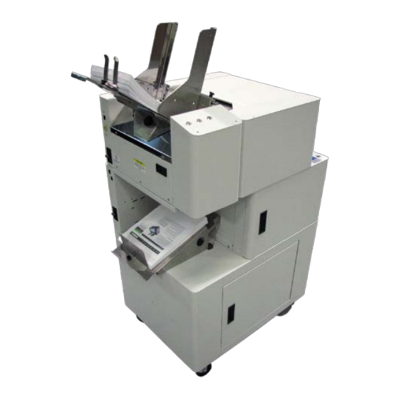
MACH 5DX DIGITAL COLOR DUPLEX PRINTER (MACH 5 PRINTER NOT INCLUDED) SERVICE GUIDE Revised: 11-22-17 Neopost Digital Print Group 3100 Horizon Dr., STE 100 King of Prussia, PA 19406-2660 Phone: (610) 650-9170 www.neopost.com www.haslerinc.com www.renausa.com... -
Page 2: Safety Precautions
In addition, follow any specific occupational safety and health standards for your workplace or area. This manual is intended solely for the use and information of Neopost, its designated agents, customers, and their employees. The information in this guide was obtained from several different sources that are deemed reliable by all industry standards. -
Page 3: Table Of Contents
TABLE OF CONTENTS Table of Contents SECTION 1 – Installation Contents of Packaging Choose a Location Unpack and Set-up Remove Transport Locks Remove Service Station Transport Tab and Shipping Tape Install Adapter Feet on Top Printer Install Top Printer on Duplex (Bottom) Printer Connecting Printers Overview: Install Firmware and Printer Driver on Top Printer Printer Driver (Top Printer) - Page 4 TABLE OF CONTENTS SECTION 4 – Disassembly/Assembly Procedures Duplex Unit Basic Disassembly Service Disassembly Procedures Operator Side Door Non-Operator Side Cover Replace Control Panel Circuit Board Feeder End Cover Replacing Wire Harness Conduit Chain Replacing Power Supply Replacing Ethernet Switch Replacing Duplex Feeder Position Sensor Replacing Print Engine Entry Sensor Replacing Print Engine Latch Sensor...
- Page 5 TABLE OF CONTENTS SECTION 5 - Maintenance Maintenance Schedule Replacing Ink Tanks Cleaning Ink Tank Contacts Cleaning/Replacing Printhead Cartridge Cleaning/Replacing Ink Revolvers Cleaning Ink Revolver Couplings Replace Ink Revolvers Cleaning Pen Driver Printed Circuit Board Contacts Replacing Printhead Latch Replacing Printhead Latch Solenoid Replace Upper and Lower Clamshell Latch Pins Replace Upper Latch Pins Replace Lower Latch Pins...
-
Page 7: Section 1 - Installation
SECTION 1 INSTALLATION SECTION 1 – Installation Contents of Packaging Duplex Printer Ink Tanks – Cyan, Magenta, Yellow, Black, Black Printhead Cartridge Envelope Attachment Spacers (pkg. of 2) AC Power Cord Ethernet Cable (to connect Top Printer and Duplex Printer) Adapter Feet for Top Printer (pkg. -
Page 8: Remove Transport Locks
SECTION 1 INSTALLATION Remove Transport Locks Remove the Non-operator Side Cover. (6 screws.) Remove 2 screws from Print Engine Support Bracket [A]. Open Print Engine Access Door. Remove 4 screws securing Transport Locking Bracket [B] to Frame (Under Handle). Remove Bracket and save for future use. -
Page 9: Remove Service Station Transport Tab And Shipping Tape
SECTION 1 INSTALLATION Remove Service Station Transport Tab and Shipping Tape 1. Lower Duplex Feeder. Open Print Engine Access Door. Unlatch and pull out Print Engine. 2. Release two latches [A] (one on either side of Print Engine). Open top half of Clamshell by lifting both levers at same time. CAUTION HOLD ONTO BOTH LATCHES WHEN OPENING AND CLOSING PRINT ENGINE CLAMSHELL TO PREVENT DAMAGE. -
Page 10: Install Adapter Feet On Top Printer
SECTION 1 INSTALLATION Install Adapter Feet on Top Printer Install two Adapter Feet on the operator side of the Printer. These will help guide and stabilize the Top Printer onto the Duplex (Bottom) Printer. Remove the two Rubber Feet from the operator side (Control Panel side) of the Top Printer. -
Page 11: Install Top Printer On Duplex (Bottom) Printer
SECTION 1 INSTALLATION Install Top Printer on Duplex (Bottom) Printer CAUTION Two people should lift and position the Top Printer onto the Duplex (Bottom) Printer. [A] Lower the Duplex Feeder on the Duplex Printer. [B] Carefully place feet on the exit end of the Printer into the two holes located in front of the Duplex Feeder. -
Page 12: Connecting Printers
SECTION 1 INSTALLATION Connecting Printers Plugging in Printer Plug power cord (included with Duplex Printer) into receptacle [1] at rear of Duplex Printer. Plug other end into an appropriate wall receptacle. Internal power supplies in Top Printer and Duplex Printer are rated 115 to 240VAC, 50/60 Hz. -
Page 13: Overview: Install Firmware And Printer Driver On Top Printer
SECTION 1 INSTALLATION Turning Power ON and OFF Powering Up Printer: Press Main Power Switch on Rear Panel. Press Power Button on Control Panel. Powering Down Printer: CAUTION WHENEVER POWERING DOWN UNIT, ALWAYS: 1. PRESS POWER BUTTON ON CONTROL PANEL. 2. -
Page 14: Printer Driver (Top Printer)
SECTION 1 INSTALLATION Printer Driver (Top Printer) Before installing the Printer Driver on the Top Printer: If the Top Printer already has a Printer Driver installed, you will have to uninstall the existing Printer Driver from the Top Printer. If the Top Printer is new or has never been installed you can proceed to “Install Printer Driver”. - Page 15 SECTION 1 INSTALLATION A window opens telling you the Printer was successfully uninstalled. Click “Finish”. A window opens telling you the system must be rebooted to complete the process. Save any open files and close other applications. Click “Reboot”.
-
Page 16: Install Over Usb Connection
SECTION 1 INSTALLATION Install Printer Driver The Printer Driver can be installed using the USB connection or the Network connection. For Network connection, there are two ways to install the Driver: Using Auto IP (network automatically assigns the IP address, this is the default). - Page 17 SECTION 1 INSTALLATION License Agreement. Check “I accept…” then click “Next>”. Printer Connections. Click “Configure to print using USB”. Then click “Next>”. Installing Printer Software. Software download begins. Would You Like to Install This Device Software? Click “Install”. Connect Device Now. Turn Printer ON and connect USB cable.
-
Page 18: Install Over Network Connection, Version A
SECTION 1 INSTALLATION Finished software installation. Do not check the Print Test Page as Printer is not set up yet. You can check “Set this printer as the default printer” at this time. Click “Finish”. Install Printer Software. Click “Exit” to close CD. 10. - Page 19 SECTION 1 INSTALLATION License Agreement. Check “I accept…” then click “Next>”. Printer Connections. Click “Configure to print using the Network”. Make sure the Printer is connected to the Network. Then click “Next>”. Printers Discovered. A list of available Printers opens. Check the Printer column to verify you have an M-Series printer.
- Page 20 SECTION 1 INSTALLATION Finished software installation. Do not check the Print Test Page as Printer is not set up yet. You can check “Set this printer as the default printer” at this time. Click “Finish”. Install Printer Software window. Click “Install Print Software” again to install software on another Printer, or click “Exit”...
-
Page 21: Install Over Network Connection, Version B
SECTION 1 INSTALLATION Install Over Network Connection, Version B Use this procedure to install the Print Driver over the Network connection on Static IP systems requiring that an IP address is assigned manually instead of automatically. NOTE: Copy the 12-digit Hardware ID number listed on the Printer(s) on the label just below Ethernet port so you can identify the Printer(s) in a later step. - Page 22 SECTION 1 INSTALLATION Finished software installation. Do not check the Print Test Page as Printer is not set up yet. You can check “Set this printer as the default printer” at this time. Click “Finish”. Install Printer Software window. Click “Exit” to close the CD. Tip: To help distinguish between multiple M-Series Drivers on your system;...
-
Page 23: Install Firmware On Top Printer
SECTION 1 INSTALLATION Install Firmware on Top Printer IMPORTANT! This procedure is for updating the firmware on the Top Printer. NOTE: The firmware on the Duplex Printer is already installed. IMPORTANT! BEFORE STARTING ANY PRINTER FIRMWARE UPDATE, REMEMBER TO USE THE PRINTER DRIVER TO FIRST EXPORT ANY CUSTOM MEDIA SIZES, WATERMARKS OR PRINT SETTINGS YOU HAVE ADDED TO AN OUTSIDE HOLDING FILE. - Page 24 SECTION 1 INSTALLATION Once the “printer firmware was successfully updated” window appears, click “OK”. NOTE: If the Update Software dialog box continues to run you can close it now. “Update printer firmware” window appears again: • If this is the only printer being updated, click “Cancel”.
-
Page 25: Set Up Top And Bottom Printer Communication
SECTION 1 INSTALLATION Set Up Top and Bottom Printer Communication Use the Printer Toolbox to select the following settings to allow the Top and Bottom Printers to synchronize and communicate. Open the Printer Toolbox. Open the Service Menus. (Enter the password to open) Click “Submit”. -
Page 26: Install Ink Tanks
SECTION 1 INSTALLATION Install Ink Tanks Printer uses one Printhead Cartridge and five Ink Tanks (two Black, one Cyan, one Magenta, and one Yellow). Open Printer Toolbox. Ink Tank Levels information (Top Row is Top Printer, Bottom Row is Duplex Printer) appears on left side corner of System Status window. - Page 27 SECTION 1 INSTALLATION Insert Ink Tanks (labels up) into appropriate color slots [B]. Close three Ink Tank Latches. INSTALLATION TIP: Make sure Ink Tanks seat properly. Insert Ink Tank into appropriate Ink Station, then pull Ink Tank back about an inch and push forward firmly to insure that Ink Nozzles penetrate seals on Ink Tanks.
-
Page 28: Install Printhead Cartridge
SECTION 1 INSTALLATION Install Printhead Cartridge Printhead Cartridge is a delicate precision device. Handle with extreme care to avoid damage and issues that could degrade print quality. CAUTION • Use electrostatic discharge (ESD) protection when handling. • Hold Printhead Cartridge by handles ONLY. •... - Page 29 SECTION 1 INSTALLATION [A] Carefully remove Printhead Cartridge from foil packaging. Tear foil at notch or cut the end with scissors. [B] Remove protective plastic cover. Hold Printhead by handle and unclip cover from Printhead. [C] Remove protective strip from Printhead Electrical Contacts.
- Page 30 SECTION 1 INSTALLATION Wet Printhead Surface [A]. (Ensures that Printhead will prime correctly.) Release and lift two latches at same time to raise Print Engine Clamshell. Moisten Printhead nozzles using distilled water and a damp, lint-free cloth, wiping end to end. (Gray strip located below orange strip.) Close and latch Print Engine Clamshell.
-
Page 31: Adjust Printer Alignment
SECTION 1 INSTALLATION Adjust Printer Alignment Alignment between the Top and Bottom Printers' media paths is critical for accurate printing. While minor adjustments to media positioning can be made in the Printer Toolbox on the Printer Control Config screen or on the Layout Tab of the Printer Driver, it may be necessary to physically align the Print Engines' media paths. - Page 32 SECTION 1 INSTALLATION Remove Locking Knob from one of the Media Guides on the Top Printer. Screw the Locking Knob into the center hole in the Rear Transport Bracket [B]. With the Print Engine pushed all the way into the cabinet, turn the Knob clockwise in small increments to push the Print Engine toward the Operator Side.
-
Page 33: Section 2 - Troubleshooting
SECTION 2 TROUBLESHOOTING SECTION 2 – Troubleshooting This section is arranged by first the condition that might occur, and then by possible problems, their cause and recommended solutions. Power Problems CONDITION PROBLEM SOLUTION Power is ON, nothing No power to Printer. Check that power cord is plugged in. -
Page 34: Feeding Problems
SECTION 2 TROUBLESHOOTING Feeding Problems CONDITION PROBLEM SOLUTION Intermittent feeding Feed Ramp not used. Feed Ramp adds a slope to stack and helps feeding. Side Guides set improperly. Loosen Side Guides slightly. Dirty Feed Rollers. Clean Feed Roller with distilled water and a cloth. -
Page 35: Memjet Printhead
SECTION 2 TROUBLESHOOTING Memjet Printhead CONDITION PROBLEM SOLUTION Missing parts of letters Clean Printhead using recirculation, Air and bubbles blocking or text. nozzles. priming or cycles of depriming and priming found in Driver or Toolbox*. Printhead is dry. Rehydrate Printhead using distilled water and a wet, clean, lint-free cloth. -
Page 36: Memjet Print Engine Main Printed Circuit Assembly (Mpca)
SECTION 2 TROUBLESHOOTING Memjet Print Engine Main Printed Circuit Assembly (MPCA) LABEL COMING FROM DESCRIPTION Driver Printed Circuit Assembly Power Supply. (DPCA) J1002 Feeder Encoder Feeder Encoder Reader Board Control. P2004 Service Station Home Sensor, Service Station Index Sensor, Service Station Lift Up Sensor, Lower Clamshell Duplex Exit Sensor,... - Page 37 SECTION 2 TROUBLESHOOTING MPCA (Continued) LABEL COMING FROM DESCRIPTION Motor PWM Control/Encoder signals for: (a) Print Engine Driver Printed Paper Motor, Circuit Assembly (DPCA) (b) Print Engine Pump Motor, (c) Feeder Motor, (d) Wiper Motor P2006 Power/LED/Printer Control Panel Indicator LEDs Printhead QAI Bus and 2.5 VDC QAI power, 3.3 VDC Logic Power...
- Page 38 SECTION 2 TROUBLESHOOTING MPCA (Continued) LABEL COMING FROM DESCRIPTION Ink Level Optical Sensors, Print Engine Ink level PCA, Accelerometer (Level Pinch Valve, Ink Sensor), Pinch Valve Cartridge QAI Actuator and Position interfaces Sensors, Ink Cartridge QAI, Temperature Sensor. P2005 Service Station Lifter Motor &...
- Page 39 SECTION 2 TROUBLESHOOTING MPCA (Continued) LABEL COMING FROM DESCRIPTION Printhead Latch Solenoid, Printhead Latch Upper Clamshell Open/Closed Sensor, Label Gap IR Transmitter LED. J2001 Power Button ON/OFF Switch. J1000 Data Input to J250 (CAT-5) PPCA Printhead. Data Input to J260 (CAT-5) PPCA Printhead.
-
Page 40: Print Engine Dpca Wire Connections
SECTION 2 TROUBLESHOOTING Print Engine DPCA Wire Connections LABEL COMING FROM J17A Main Transport Motor J17B Ink Pump J18C External Feeder Motor J17E Wiper Roller Assy. Motor J1002 on MPCA P2006 on MPCA Service Station CONDITION PROBLEM SOLUTION • Motor stalls Check each possible cause Jammed gear train due to and correct if possible:... -
Page 41: Printing Problems
SECTION 2 TROUBLESHOOTING Printing Problems CONDITION PROBLEM SOLUTION Ink Tank installed, no Ink Level Ink Tank contacts dirty, Remove Ink Tank(s). Clean indication in Toolbox preventing Printer/Ink Tank prism and QA Chip contacts, see Maintenance, Cleaning Ink communication. Tank Contacts. Extra lines;... -
Page 42: Errors And Warnings
SECTION 2 TROUBLESHOOTING Errors and Warnings Printer Alert Window Messages Messages sent from Driver and displayed on PC screen in a small popup window. MESSAGE SOLUTION Wait until message disappears. Printer will start printing your job once Cleaning in Progress cleaning process is complete. -
Page 43: Toolbox System Status Messages
SECTION 2 TROUBLESHOOTING Toolbox System Status Messages (Valid for printers with firmware version 14.3 or higher installed.) Use the Duplex Toolbox System Status screen to quickly determine and locate a problem in the Printers. Status Indicator shows ERROR shows in red box. Printer Graphic Icon highlights which Printer and system is affected. The System Status information on the right displays the basic problem (in red) and which of the two Printers (Top or Bottom) is affected. - Page 44 SECTION 2 TROUBLESHOOTING Toolbox System Status Messages (Continued) SYSTEM STATUS SOURCE SOLUTION Indicates that Verify that Clamshell is closed “Clamshell” is open. and securely latched on both sides. Make sure that Clamshell Sensor cable switch (located on opposite side) unplugged P202. is activated by Clamshell Lever.
- Page 45 SECTION 2 TROUBLESHOOTING Toolbox System Status Messages (Continued) SYSTEM STATUS SOURCE SOLUTION Ink Tank(s) missing or Insert missing Ink Tank(s) or pop not recognized Ink Tank in and out to improve (obtained from an connection. unauthorized reseller). Clear error using “Refresh Ink If correct ink, check Levels”...
- Page 46 SECTION 2 TROUBLESHOOTING Toolbox System Status Messages (Continued) SYSTEM STATUS SOURCE SOLUTION Mechanical error Using Scan Sensors page in Toolbox, perform toggle test on One of Printer's Sensor responsible for mechanical registration of failed mechanical components was not component position. properly registered at ERROR on System Status screen.
- Page 47 SECTION 2 TROUBLESHOOTING Toolbox System Status Messages (Continued) SYSTEM STATUS SOURCE SOLUTION No Printhead installed If Printer was just powered on, or Printhead not wait a minute; error may clear making proper by itself. connections. Install Printhead Cartridge. J2001 cable Remove and reinstall Printhead.
-
Page 48: Jams In Printer
SECTION 2 TROUBLESHOOTING Jams in Printer If a jam occurs, STOP the Printer. Some possible causes for jamming are: Feeding more than one piece of media (double-feeding). Damaged media, such as dog-eared (turned down corners). Media that is not stiff enough may not be usable. Media that meets Postal stiffness requirements for automated feeding is acceptable in Printer. -
Page 49: Section 3 - Functional Operation
SECTION 3 FUNCTIONAL OPERATION SECTION 3 – Functional Operation Sequence of Operation User Prepares Printer Installs Ink Tanks in proper locations. Uses a single piece of media to set Sheet Separators. Loads media and adjusts Side Guide to within 1/32" of media. Stacks media in Feeder and adjusts Feed Ramp. -
Page 50: Duplex Printer Control Panel Button/Led Indicators
SECTION 3 FUNCTIONAL OPERATION Printer Functional Description Photosensor (located behind Sheet Separators) sees lead edge of media, another Photosensor in Print Engine signals Print Engine on Main Board that mailing piece is ready for printing. Feed Clutch remains disengaged as long as a mailing piece is in view of Photosensor. When mailing piece uncovers Sensor, Clutch engages Feed Rollers and next piece of media starts moving toward Printer section. -
Page 51: Control Panel Button/Led Indicators (Top Printer)
SECTION 3 FUNCTIONAL OPERATION Control Panel Button/LED Indicators (Top Printer) Control Panel has 3 buttons with LED indicators. POWER (ON/OFF) – Turns Printer power ON and OFF. Turns off power for cleaning and maintenance PAPER /RESUME – Press to Resume printing after a paper feed error (such as a paper jam or running out of paper) and/or after a job is paused with the Cancel button. -
Page 52: Duplex Printer Driver Properties
SECTION 3 FUNCTIONAL OPERATION Duplex Printer Driver Properties Printer Driver works the same as any other Printer Driver for Windows. It does have some enhancements to help you maximize Printer's ability to print variable addressed pieces quickly and efficiently. Once job is set up, click File, then Print. Window at right opens. - Page 53 SECTION 3 FUNCTIONAL OPERATION To create and print a job that includes a static “Back Page”: The following procedure can be used to print a job where the Top Unit prints each page of the document (usually variable-data multi-page document) as the front page and the Bottom Unit prints a preloaded “static” image on the “Back Page” of each piece.
-
Page 54: Layout Tab
SECTION 3 FUNCTIONAL OPERATION • Media – Choose a type of media or different MEDIA PROFILE MEDIA TYPE size media than document was originally Plain Paper Plain Paper designed for. Type: Chart at right lists media Bright White Paper profiles associated with type of media chosen. Presentation Paper Sizes: 21 sizes are available. - Page 55 SECTION 3 FUNCTIONAL OPERATION Using Layout Tab Printing Adjustments Image Position – Left Adjustment moves image area (-3mm left to +200mm right) from left edge of media. Top Adjustment moves image up or down (-5mm up to + 200mm down) from top left corner of media used. (0.1mm increments) Max Page Width –...
-
Page 56: Color Tab
SECTION 3 FUNCTIONAL OPERATION Color Tab Color is used to adjust the color output of the Printer. Use the sliders to adjust Color Tone, Brightness and Saturation. The C, M, Y, K sliders adjust individual colors. Use Defaults to reset to 0 settings. Import/Export Tab Import/Export is used to preserve any custom Media Sizes, Watermarks and/or Print Settings you may have... -
Page 57: Services Tab
SECTION 3 FUNCTIONAL OPERATION Services Tab Services allows you to: • Print Configuration Page – Prints out current configuration of Printer including current Firmware Version, Network Connection, printer Serial Number and more. • Print Colorbar Page – Prints type and color bands to check print quality. -
Page 58: Using Duplex Printer Toolbox
SECTION 3 FUNCTIONAL OPERATION Using Duplex Printer Toolbox Once Printer Driver is installed, you can access the Duplex Printer Toolbox. You can check Printer status, monitor ink usage, perform diagnostic checks, print reports and run maintenance tasks on both Top and Duplex Printers from your computer. -
Page 59: System Status
SECTION 3 FUNCTIONAL OPERATION System Status This screen opens when you access the Toolbox. It provides information about both Printers. Left side: Status Indicator shows Printer activity as ONLINE, ERROR, MAINTENANCE, PRINTING or PAUSED. Gray box (below Status Indicator) shows the name of the job being processed. -
Page 60: User Interface
SECTION 3 FUNCTIONAL OPERATION User Interface SET-UP SETTINGS: Adjust automated service and cleaning intervals, adjust feeder speed for a job, manually set gap between pieces and adjust Printer for pre-printed media. KWS Setting – (Keep Wet Spitting) Keeps Printhead hydrated while running a job. - Page 61 SECTION 3 FUNCTIONAL OPERATION DISPLAY LANGUAGE: Selects language EWS (Toolbox) will display. Click “Submit” after selecting language. FIRMWARE DOWNLOAD: Get the latest version of firmware for your Printer. Two types of firmware files are normally provided: “.bin” files and “.fbf” files.
-
Page 62: Ink Usage
SECTION 3 FUNCTIONAL OPERATION Ink Usage Allows you to monitor estimated amount of ink left in each Ink Tank. Monitor ink use and consumption and schedule Tank changes (saving down-time during a print run.) NOTE: Ink Usage only works when a new Ink Tank is installed and left in the Printer. -
Page 63: Service Menus
SECTION 3 FUNCTIONAL OPERATION Service Menus Clicking Service Menus opens the Service Menus screen. Diagnostics button. Click to check the status of both Top Printer and Bottom (Duplex) Printer. (See Diagnostics below.) Network Config button. Click to view, enter or change settings to connect Printer to your network. -
Page 64: Network Configuration
SECTION 3 FUNCTIONAL OPERATION Network Configuration Permits you to view, enter or change settings to connect Printer to your network. Network Connection Set Up: NOTE: If Top Printer is connected to a computer via USB, skip to Step 2. If the Top Printer is connected to a network via the Ethernet Port, see Step 1 below. - Page 65 SECTION 3 FUNCTIONAL OPERATION Scan Sensors Provides status and log on Sensors located throughout both Printers. (See chart at right.) Click “Stop” button to stop scanning or click out of “Scan Sensors”. SENSOR DESCRIPTION Entry Sensor Interrupted (media present) = 0-60 (Paper Path Entry) Uninterrupted (no media) = 255 Blackmark Sensor...
-
Page 66: Advanced Service Menus
SECTION 3 FUNCTIONAL OPERATION Advanced Service Menus Enter the Service Menu password and click “Submit” for access to more advanced Printer control and maintenance menus. Printer Control Config Allows you to make fine adjustments as to how a job is fed into and through the Printers and how it will print. - Page 67 SECTION 3 FUNCTIONAL OPERATION Top Unit and Bottom Unit Top Unit switches back to the Standard Printer Toolbox view and shows information for the Top Unit (Top Printer). Bottom Unit switches to the Standard Printer Toolbox view but shows information for the Bottom Unit (Duplex Printer). NOTE: Printer Maint Config and Printer Commands Help (see below) are only available in the both the Top and Bottom Unit Standard Toolbox view: Exit Service Menus...
-
Page 68: Maintenance Drop-Down
SECTION 3 FUNCTIONAL OPERATION Maintenance Drop-Down Perform maintenance tasks. Select drop-down menus for Top Unit or Bottom Unit. Circulate Ink – Purges air from lines and primes system after replacing Ink Tanks or Printhead Cartridge. Quick Clean Printhead – Circulates ink; wipes and cleans Printhead Cartridge. -
Page 69: Print Drop-Down
SECTION 3 FUNCTIONAL OPERATION Print Drop-Down Print various reports and Printer tests. Each printout displays information about both Printers. Print Setup – Prints a printing pattern used for positioning image on the page. (Duplex Printer: the same page is printed on both units to help align top and bottom Printers.) Print Configuration –... -
Page 70: Updating Firmware
SECTION 3 FUNCTIONAL OPERATION Updating Firmware Get latest version of firmware for your Printer. This may be in the form of a CD or download. In many cases the Firmware and Printer Driver are updated at the same time. Two types of firmware files are normally provided: “.bin”... - Page 71 SECTION 3 FUNCTIONAL OPERATION Download new firmware using the Printer Toolbox and “.fbf” files: WARNING: Firmware download procedure using the “.fbf” file should only be performed by qualified service personnel. In some cases firmware must be loaded using “Firmware Migration Tool”. If this process is not performed properly, Printer is rendered inoperable.
-
Page 72: Section 4 - Disassembly/Assembly Procedures
SECTION 4 DISASSEMBLY AND ASSEMBLY SECTION 4 – Disassembly/Assembly Procedures Duplex Unit Basic Disassembly • Turn off Power • Disconnect Power Cord • Disconnect Interface Cable Service Disassembly Procedures WARNING! THE FOLLOWING DISASSEMBLY SHOULD ONLY BE DONE BY A QUALIFIED, TRAINED SERVICE REPRESENTATIVE. -
Page 73: Operator Side Door
SECTION 4 DISASSEMBLY AND ASSEMBLY Operator Side Door Open Print Engine Access Door [A]. Components behind Operator Side Door Print Engine Print Engine Release Latch and Print Engine Latch Sensor Wire Harness Conduit Chain Duplex Feeder Indicator Panel Printed Circuit Board Power On/Off Switch... -
Page 74: Non-Operator Side Cover
SECTION 4 DISASSEMBLY AND ASSEMBLY Non-Operator Side Cover Upper Non-Operator Side Cover: Remove (3) screws at top and (3) screws from bottom of Cover. Major Components under Upper Non-Operator Side Cover Print Engine Ethernet Switch Ethernet Ports (2) Ethernet Switch Power Receptacle Main Power Switch, Fuse and Power Receptacle... -
Page 75: Feeder End Cover
SECTION 4 DISASSEMBLY AND ASSEMBLY Feeder End Cover Remove Feeder End Cover: [A] Remove 3 screws across bottom of Cover. [B] Remove 2 screws (one on each side inside Cabinet.) [C] Remove 2 screws on top. Remove Cover. Major Components under Feeder End Cover Print Engine Duplex Feeder Duplex Feeder Cover Sensor... -
Page 76: Replacing Wire Harness Conduit Chain
SECTION 4 DISASSEMBLY AND ASSEMBLY Replacing Wire Harness Conduit Chain Open Print Engine Door. Remove upper Non-Operator Side Cover (6 screws) and Feed End Cover [A], [B] and [C]. Remove MPCA Cover. (4 screws). - Page 77 SECTION 4 DISASSEMBLY AND ASSEMBLY Disconnect these Wire Harnesses: From MPCA: [A] Ethernet, [B] P1000 (Power Supply), [C] J1000, [D] P2004, [E] Control Panel Indicator wire harness, From DPCA: [F] DPCA-J18C Cut cable ties securing wiring harnesses to chain as necessary. Carefully pull the disconnected wire harnesses free of other wiring, the MPCA and the Print Engine.
-
Page 78: Replacing Power Supply
SECTION 4 DISASSEMBLY AND ASSEMBLY Replacing Power Supply Remove upper Non-Operator Side Panel. (6 screws) Disconnect wire harnesses [A] from Power Supply. NOTE: Wires are labelled to simplify reconnection. Remove 2 mounting screws and washers [B]. (Access screws from exit end of Duplex Printer.) Reinstall in reverse order. -
Page 79: Replacing Ethernet Switch
SECTION 4 DISASSEMBLY AND ASSEMBLY Replacing Ethernet Switch Remove upper Non-Operator Side Panel. (6 screws) Disconnect Ethernet Cables [A] from Ethernet Switch. Unplug Power Cord from Switch [B]. Unplug Power Cord plug from outlet [C]. Unclip Power Cord and remove. Switch is attached with hook and loop strip. -
Page 80: Replacing Duplex Feeder Position Sensor
SECTION 4 DISASSEMBLY AND ASSEMBLY Replacing Duplex Feeder Position Sensor Lower Duplex Feeder (6 screws). Remove Duplex Feeder Sensor mounting screws (2 screws). Disconnect wire harness. Reinstall in reverse order. -
Page 81: Replacing Print Engine Entry Sensor
SECTION 4 DISASSEMBLY AND ASSEMBLY Replacing Print Engine Entry Sensor The Entry Sensor (Emitter) is located on the upper clamshell at the media entry end of the Duplex Print Engine. NOTE: To remove the Receiver component of this Sensor, you must first remove the Print Engine's Upper Clamshell Assembly. -
Page 82: Replacing Print Engine Latch Sensor
SECTION 4 DISASSEMBLY AND ASSEMBLY Replacing Print Engine Latch Sensor Lower Duplex Feeder. Open Print Engine Access Door. Unlatch and pull out Print Engine. Remove 2 screws [A] securing Sensor to Print Engine Latch Assembly. Disconnect NC and COM wire harnesses. Reinstall in reverse order. -
Page 83: Replacing Print Engine Latch
SECTION 4 DISASSEMBLY AND ASSEMBLY Replacing Print Engine Latch Lower Duplex Feeder. Open Print Engine Access Door. Unlatch and pull out Print Engine. Remove 2 screws [A] securing Sensor to Print Engine Latch Assembly. Move Sensor away from Latch Assembly Open the Storage Door (below the Print Engine Access Door). -
Page 84: Removing Duplex Feeder Assembly
SECTION 4 DISASSEMBLY AND ASSEMBLY Removing Duplex Feeder Assembly Disconnect and remove the Top Printer. Remove Non-operator Side Cover. (6 screws.) Open Print Engine Access Door. Remove Feeder End Cover: [A] Remove 3 screws across bottom of cover. [B] Remove 2 screws (one on each side inside Cabinet.) [C] Remove 2 screws on top. - Page 85 SECTION 4 DISASSEMBLY AND ASSEMBLY Disconnect SW2, ENCOD and MOTOR wire connectors and unsnap wires from wire clip. Support Assembly. Remove 2 screws (one on each side) holding Feeder Pivot Arm to Duplex Printer Cabinet. Continue to support Assembly. Remove 2 screws (one on each side) holding Feeder Arms to Duplex Printer Cabinet.
-
Page 86: Replacing Duplex Feeder Cover Sensor
SECTION 4 DISASSEMBLY AND ASSEMBLY Replacing Duplex Feeder Cover Sensor Remove Upper Non-Operator Side Cover: Remove (3) screws at top of Cover. Remove (3) screws from bottom of Cover. Remove 1 mounting screw [A] securing the Sensor to side of Duplex Feeder. -
Page 87: Removing Duplex Feeder Cover
SECTION 4 DISASSEMBLY AND ASSEMBLY Removing Duplex Feeder Cover Remove 4 mounting screws (2 on each side). Remove Cover. Reinstall in reverse order. NOTE: When reinstalling Feeder Cover, pull up on the Cover as you tighten screws or Cover may rub against the Drive Belt and/or not contact the Feeder Sensor Switch. -
Page 88: Replacing Duplex Feeder Motor Assembly
SECTION 4 DISASSEMBLY AND ASSEMBLY Replacing Duplex Feeder Motor Assembly Remove Duplex Feeder Cover (4 screws). Remove Motor mounting screws [A] (2 screws). Disconnect wire harnesses [B]. Cut cable tie if necessary. Remove Motor Assembly. Reinstall in reverse order. NOTE: When reinstalling Feeder Cover, pull up on the Cover as you tighten screws or Cover may rub against the Drive Belt and/or not contact the Feeder Sensor Switch. - Page 89 SECTION 4 DISASSEMBLY AND ASSEMBLY Remove Bearing Housing Assemblies [B] for the four Roller Shafts (4 per side). Remove four Roller Shafts. Remove Drive Belt. Install new Drive Belt around Roller Shaft Pulleys and Idler Pulleys [C] on Roller Shaft Assemblies. Reinstall the Roller Shaft Bearing Housing Assemblies.
-
Page 90: Adjusting Duplex Feeder Drive Belt Tension
SECTION 4 DISASSEMBLY AND ASSEMBLY Adjusting Duplex Feeder Drive Belt Tension Remove Duplex Feeder Cover. Loosen Idler Roller mounting screw [A]. Slide Idler Roller Assembly up or down to adjust Belt tension [B]. (Approximately 1/8" of deflection.) Hold Idler Roller Assembly in place while retightening Idler Roller mounting screw. -
Page 91: Removing Print Engine
SECTION 4 DISASSEMBLY AND ASSEMBLY Removing Print Engine Remove Upper Non-Operator Side Cover: Remove (3) screws at top of Cover. Remove (3) screws from bottom of Cover. Disconnect Network (Ethernet) cable [1] and power supply cable [2] from MPCA. Carefully disconnect Wire Harness Connectors (wire harnesses are labelled): To MPCA: A, B, C To DPCA: D... - Page 92 SECTION 4 DISASSEMBLY AND ASSEMBLY Lower Duplex Feeder. Unlatch and pull out Print Engine. Reach under Print Engine to access and remove (4) screws securing bottom of Print Engine to Base Plate. Carefully lift Print Engine out of Printer. (Print Engine is entire unit including Ink Station.) NOTE: Make sure no wire harnesses get snagged or pulled while...
-
Page 93: Replace Print Engine Slide Brackets
SECTION 4 DISASSEMBLY AND ASSEMBLY Replace Print Engine Slide Brackets Remove Print Engine, upper Non- Operator side Cover, and Rear Cover. Remove Print Engine Tray: Open Print Engine Access Door. Slide Print Engine Tray out. Remove screws securing Mounting Plate to Sliding Bracket. -
Page 94: Print Engine Basic Disassembly
SECTION 4 DISASSEMBLY AND ASSEMBLY Print Engine Basic Disassembly Print Engine must be removed from Printer for these procedures. See “Removing Print Engine” on previous pages. It is also assumed that Ink Tanks, Printhead and Service Station are also removed. Remove Print Engine Base Provides access to parts located underneath Print Engine. -
Page 95: Replacing Peristaltic Pump Assembly
SECTION 4 DISASSEMBLY AND ASSEMBLY Replacing Peristaltic Pump Assembly Remove old Pump Assembly: [A] Remove (4) screws that hold Bracket to Chassis. [B] Cut cable tie holding wiring harness to Assembly. [C] Unplug connector from Pump Motor Circuit Board. [D] Cut as shown or remove hoses from barbs. IMPORTANT! Make sure you know where each Ink Hose connects. -
Page 96: Cleaning Dual Pinch Valve Sensors
SECTION 4 DISASSEMBLY AND ASSEMBLY Cleaning Dual Pinch Valve Sensors If “Ink Valve: Unknown” (displays as “?”) appears for more than a few seconds in the Printer icon on the Status screen in the Duplex Toolbox, it may indicate that the Dual Pinch Valve (DPV) Sensors are dirty or blocked. -
Page 97: Replacing Dual Pinch Valve Sensor Pc Board
SECTION 4 DISASSEMBLY AND ASSEMBLY Replacing Dual Pinch Valve Sensor PC Board Dual Pinch Valve Sensor PC Board Replacement Kit (42-900-85) includes a new Sensor Printed Circuit Board, (3) inserts and a Pinch Valve Wrench. Inserts prevent Sensor PC Board from being misaligned during replacement. Pinch Valve Wrench holds spring-loaded Pinch Valve Shaft in place while replacing PC Board. - Page 98 SECTION 4 DISASSEMBLY AND ASSEMBLY Remove Motor Assembly. Remove three (3) screws [A] holding Pinch Valve Motor Assembly on Pinch Valve Body. Remove Motor Assembly. Remove one (1) screw to remove Pinch Valve Sensor PC Board. Install new Pinch Valve Sensor PC Board using screw removed in Step 3.
-
Page 99: Replacing Dpca Board
SECTION 4 DISASSEMBLY AND ASSEMBLY Replacing DPCA Board [A] Remove (2) screws on outside of Chassis that attach Circuit Board Bracket to Chassis. [B] Carefully move DPCA Assembly out to unplug wire harness connectors. NOTE: Make sure you know which connectors go with which socket. -
Page 100: Replacing Buffer Boxes (3 Per Machine)
SECTION 4 DISASSEMBLY AND ASSEMBLY Replacing Buffer Boxes (3 per machine) [A] Each Buffer Box is held in place by (2) screws accessed through Ink Tank Station. Use a long Phillips screwdriver to remove screws and pull up on box to remove it from chassis. [B] If necessary, remove Tubing Inserts (2) from used Buffer Box and insert... -
Page 101: Removing Pen Driver Printed Circuit Assembly (Pca)
SECTION 4 DISASSEMBLY AND ASSEMBLY Removing Pen Driver Printed Circuit Assembly (PCA) Location: Upper Clamshell next to Printhead Cartridge bay. [A] Remove Pen Driver PCA Cover (lightly glued in place). [B] Disconnect (2) Ethernet data cables, then unplug power connector and Main PCA harness connectors. [C] Remove (3) screws holding Head Board Mount. -
Page 102: Replacing Ink Tank Latches
SECTION 4 DISASSEMBLY AND ASSEMBLY Internal: [A] Remove Pen Driver Printed Circuit Board Cover. [B] Remove (2) screws from bottom of Pen Driver Printed Circuit Board bay. [C] Locate and carefully release (2) black locking tabs holding Starwheel Assembly to metal bracket. NOTE: Locking tabs break easily! Remove Starwheel Assembly. -
Page 103: Main Printed Circuit Assembly (Mpca) Cover
SECTION 4 DISASSEMBLY AND ASSEMBLY Main Printed Circuit Assembly (MPCA) Cover Removing Main Printed Circuit Assembly Cover To access parts on Print Engine Clamshell, MPCA Panel Cover must be removed and Panel folded out of the way. Remove (4 or 5) screws to remove Cover. Set Cover aside. -
Page 104: Replacing Encoder Or Encoder Sensor
SECTION 4 DISASSEMBLY AND ASSEMBLY Replacing Encoder or Encoder Sensor [A] Remove (3) screws holding Encoder Cover. [B] Unplug wire harness from Encoder Sensor. [C] Carefully pivot Cover away from Encoder Wheel. Be careful of spring. [D] Remove (2) screws holding Encoder Sensor in place and pull away from Encoder Wheel. -
Page 105: Replacing Paper Path Motor Or Drive Belt
SECTION 4 DISASSEMBLY AND ASSEMBLY Replacing Paper Path Motor or Drive Belt [A] Remove (2) screws that attach Motor Assembly to lower Print Engine Clamshell. Pull Motor straight out so Motor Pulley clears Drive Belt. NOTE: If removing Motor, unplug two wire connectors. [B] If removing Drive Belt, remove Encoder Assembly (see “Replacing Encoder or Encoder Sensor”). -
Page 106: Adjust Paper Path Motor Drive Belt Tension
SECTION 4 DISASSEMBLY AND ASSEMBLY Adjust Paper Path Motor Drive Belt Tension [A] Loosen Drive Belt Tensioner Locking Screw. [B] Push and release Belt Tensioner Roller to release tension on Drive Belt. [C] Use your finger to push belt clockwise one full revolution around rollers. -
Page 107: Replacing Belt Drive Gear Pulleys
SECTION 4 DISASSEMBLY AND ASSEMBLY Replacing Belt Drive Gear Pulleys There are three. One is mounted on Exit Grit Roller Shaft, one is located behind Encoder Assembly on another Grit Roller Shaft and one is mounted on Entry Grit Roller Shaft. First, you may need to loosen or remove Drive Belt, see “Replacing Paper Path Motor or Drive Belt”. -
Page 108: Replacing Lifter Motor Assembly Or Lifter Gear
SECTION 4 DISASSEMBLY AND ASSEMBLY Replacing Lifter Motor Assembly or Lifter Gear Remove Lifter Motor Assembly Only [A] Unplug wire harness from Lifter Motor Assembly. [B] Remove (2) screws holding Motor Assembly to Motor Assembly Bracket. [C] Gently remove Motor Assembly. Take care that Worm Gear does not damage Lifter Gear. -
Page 109: Replacing Stepper Motor
SECTION 4 DISASSEMBLY AND ASSEMBLY Replacing Stepper Motor [A] Remove (2) screws. [B] Unplug wire harness from Stepper Motor Printed Circuit Board. [C] Note position of motor gears to make sure gears will mesh with Service Station gear (if Service Station is installed.) Install in reverse order. - Page 110 SECTION 4 DISASSEMBLY AND ASSEMBLY Lubricating Grit Roller Ground Clips Three Ground Clips are located on right side of Print Engine, at ends of Grit Roller Shafts. To access them, remove Lifter Motor and Stepper Motor. See “Replacing Lifter Motor” and “Replacing Stepper Motor”...
-
Page 111: Clamshell Assembly
SECTION 4 DISASSEMBLY AND ASSEMBLY Clamshell Assembly Provides access to parts under Clamshell Assembly. Removing Clamshell Assembly Remove (4) screws attaching Clamshell to Chassis (1 at each corner). Gently lift Clamshell from Chassis. Take care not to pinch or damage any wires or Ink Hoses. -
Page 112: Replacing Service Station Sled Printed Circuit Boards
SECTION 4 DISASSEMBLY AND ASSEMBLY Replacing Service Station Sled Printed Circuit Boards [A] Remove (2) screws. [B] Carefully disconnect (2) connectors. [C] Swing Sled away from Clamshell and turn over. Carefully unclip two Printed Circuit Boards. Install reverse order. NOTE: Make sure wire harnesses are plugged into correct Printed Circuit Board. -
Page 113: Replacing Duplex Exit Sensor
SECTION 4 DISASSEMBLY AND ASSEMBLY Replacing Duplex Exit Sensor Located under left side exit end of the Print Engine. Open the Print Engine Access Door. Lower the Duplex Feeder. Unlatch and pull out Print Engine. [A] Release two Latches. Open Print Engine Clamshell. [B] Remove (2) screws from Operator side of Exit Center Plate Assembly. - Page 114 SECTION 4 DISASSEMBLY AND ASSEMBLY Detach Exit Roller from Operator side. NOTE: Be careful not to drop or lose bearing. Then pivot Exit Center Plate up out of the way. (Sensor is on underside of Center Plate). [A] Remove Exit Sensor mounting screw (1 screw). [B] Carefully pull Exit Sensor away from mounting bracket.
-
Page 115: Replacing Duplex Entry Sensor
SECTION 4 DISASSEMBLY AND ASSEMBLY Replacing Duplex Entry Sensor Entry Sensor consists of a Receiver (located in lower Clamshell) and an Emitter (on upper Clamshell). NOTE: For easier access to the Sensors, remove the Print Engine Media Entry Assembly [A] (2 screws). -
Page 116: Reinstall Main Printed Circuit Board Assembly
SECTION 4 DISASSEMBLY AND ASSEMBLY Reinstall Main Printed Circuit Board Assembly Gently lift up Wiring Panel. NOTE: DO NOT pinch or cut wires running through Frame. Reinstall two (2) mounting screws into bottom of MPCA Panel. Reinstall Cover (4 screws). -
Page 117: Section 5 - Maintenance
SECTION 5 MAINTENANCE SECTION 5 - Maintenance General, periodic maintenance is needed to keep Printer in good working order. Many tasks can be performed by operators with basic supplies, no special tools needed. Other tasks should only be performed by trained service personnel. -
Page 118: Replacing Ink Tanks
SECTION 5 MAINTENANCE WARNING! ALWAYS POWER DOWN PRINTER BEFORE CONNECTING OR DISCONNECTING ANY WIRING HARNESSES OR CABLE CONNECTIONS TO AVOID SERIOUS SHOCK OR INJURY. CAUTION • ALWAYS USE APPROPRIATE PERSONAL PROTECTION EQUIPMENT (PPE). • USE ELECTROSTATIC DISCHARGE (ESD) PROTECTION WHEN MAINTAINING EQUIPMENT. •... - Page 119 SECTION 5 MAINTENANCE Insert new Ink Tanks (labels up) into appropriate color slots [B]. Close three Ink Tank Latches. INSTALLATION TIP: Make sure Ink Tanks seat properly. Insert Ink Tank into appropriate Ink Station, then pull Ink Tank back about an inch and push forward firmly to insure that Ink Nozzles penetrate seals on Ink Tanks.
-
Page 120: Cleaning Ink Tank Contacts
SECTION 5 MAINTENANCE Cleaning Ink Tank Contacts When reinstalling or replacing Ink Tanks; Ink Level indicator in Toolbox may not refresh. This may be due to a dirty Ink Tank Level Prism and/or QA Chip contacts on that Ink Tank(s). Clean contacts as follows: Remove Ink Tank(s). - Page 121 SECTION 5 MAINTENANCE Click “Service” drop-down menu. Select “Bottom Unit” and “Refresh Ink Levels”. Ink colors fill in as Ink Tanks are installed. If ink colors do not fill in after a few seconds, click the “Replace Ink Tanks” again and reinstall Ink Tank(s).
-
Page 122: Cleaning/Replacing Printhead Cartridge
SECTION 5 MAINTENANCE Cleaning/Replacing Printhead Cartridge Cleaning Printhead Cartridge is cleaned automatically each time Printer is turned on or when “Quick Clean Printhead” routine is performed. (Found under Service Tab, “Quick Clean Printhead” in Printer Driver or “System Status” screen in Printer Toolbox.) “Normal Clean Printhead” and “Full Clean Printhead” can be used to more thoroughly clean or clear Printhead. - Page 123 SECTION 5 MAINTENANCE Replacing Printhead Cartridge Open Duplex Toolbox. On System Status screen, System Status information appears on the right side. Lower Duplex Feeder. Open Print Engine Access Door on Duplex Printer. Unlatch and pull out Print Engine. Press Printhead Latch Release button [1]. Printer pumps any ink in system back into Tanks.
- Page 124 SECTION 5 MAINTENANCE [A] Carefully remove Printhead Cartridge from foil packaging. Tear foil at notch or cut the end with scissors. [B] Remove protective plastic cover. Hold Printhead by handle and unclip cover from Printhead. [C] Remove protective strip from Printhead electrical contacts.
- Page 125 SECTION 5 MAINTENANCE Wet Printhead Surface [A]. (Ensures that Printhead will prime correctly.) Release and lift two latches at same time to raise Print Engine Clamshell. Moisten Printhead nozzles using distilled water and a damp, lint-free cloth, wiping end to end. (Gray strip located below orange strip.) Close and latch Print Engine Clamshell.
-
Page 126: Printhead Service Life
SECTION 5 MAINTENANCE Printhead Storage Store and transport cartridge as indicated by “this side up” arrow symbol on packaging. Cartridge and ink supply must be within operating temperature range before attempting to prime cartridge with ink and starting to print. When stored at temperatures below operating range it may take up to 3 hours for a cartridge in its packaging to reach operating temperature. -
Page 127: Cleaning/Replacing Ink Revolvers
SECTION 5 MAINTENANCE Cleaning/Replacing Ink Revolvers First Deprime system and remove Printhead Cartridge. (New Ink Revolver includes attached leader hoses and hose connectors.) NOTE: Procedure is similar for both Valve side Ink Revolver and Pump side Ink Revolver (labeled). IMPORTANT! Make sure you replace Valve side Ink Revolver in Valve side and Pump side in Pump side. - Page 128 SECTION 5 MAINTENANCE Once all hoses have been connected to new Ink Revolver, remove C-Clip from hinge pin holding Ink Revolver. Remove pin. Slide old Ink Revolver forward in its track and remove. Slide new Ink Revolver back in its track and align yoke on rear with hinge bracket.
-
Page 129: Cleaning Pen Driver Printed Circuit Board Contacts
SECTION 5 MAINTENANCE Cleaning Pen Driver Printed Circuit Board Contacts Clean Printed Circuit Board contact pins that connect with Printhead Cartridge. Remove Printhead Cartridge. Locate contact pins along base of Pen Driver Printed Circuit Board. (Positioned opposite Ink Revolvers.) Dampen a new, lint free cloth in deionized/distilled water. -
Page 130: Replacing Printhead Latch
SECTION 5 MAINTENANCE Replacing Printhead Latch Printhead Latch is easily broken if forced open manually. Tools & Supplies needed: nitrile powder-free gloves, needle nose pliers or tweezers, small flathead screwdriver. Remove Printhead Latch Open Printer Toolbox. Open “Service” drop-down menu. Select “Bottom Unit”... - Page 131 SECTION 5 MAINTENANCE Use needle-nose pliers or tweezers to gently pull rounded end of Spring out from beneath plastic tab in housing and remove Spring. Repeat procedure to remove second Spring. Gently insert a small, flathead screwdriver between blue Printhead Latch Pin and black plastic hinge [A] and rotate to pop Printhead Latch out of hinge without damaging either piece.
- Page 132 SECTION 5 MAINTENANCE Testing Restart Printer if necessary. Open Printer Toolbox. Select “Print” drop-down menu. Click “Print Color Bars” to confirm that unit is functioning properly.
-
Page 133: Replacing Printhead Latch Solenoid
SECTION 5 MAINTENANCE Replacing Printhead Latch Solenoid To replace Lever Latch Solenoid: Remove Printhead Latch Solenoid Open Printer Toolbox. Open the “Service” drop-down menu. Select “Bottom Unit” and click “System Deprime”. Click “Release Printhead” to release Printhead Latch. Once Latch pops up, click “Shutdown” to shut down the Duplex Printer. - Page 134 SECTION 5 MAINTENANCE Remove two (2) screws securing Solenoid to Base Assembly. Cut two cable ties [A]. Unplug Solenoid connector [B] from wiring harness. Carefully lift Base Assembly just enough to remove Solenoid assembly from under Base Assembly. 10. Install new Solenoid. Reassemble in reverse order.
-
Page 135: Replace Upper And Lower Clamshell Latch Pins
SECTION 5 MAINTENANCE Replace Upper and Lower Clamshell Latch Pins Upper and Lower Latch Pin Kits replace Print Engine Clamshell Latch Pins that may be bent or broken. Replace Upper Latch Pins Upper Latch Pin Kit consists of: (1) Latch Pin, (1) 5/64 Allen screw. NOTE: Check that Latch Pins are pressed in on your Printer. - Page 136 SECTION 5 MAINTENANCE Cut and remove 2 cable ties holding wire harness to Print Engine Frame Crossmember. Remove Latch Levers (both sides). Carefully remove C-clip holding Latch Lever onto Upper Latch Pin. DO NOT LOSE! Must be reinstalled later. Repeat procedure for Latch Lever on other side. Slide Latch Lever and Spring off of Upper Latch Pin.
- Page 137 SECTION 5 MAINTENANCE 10. Use small file to enlarge and round out cutouts located on upper edge of cross-member. NOTE: This is done so crossmember will fit around mounting screw for new Latch Pin. If only replacing one Latch Pin, you only need to modify that side of crossmember.
- Page 138 SECTION 5 MAINTENANCE 14. Slide Latch Lever Spring onto Latch Pin. Then slide Latch Lever for that side onto Pin. Repeat procedure for other side. 15. Maneuver spring so upper arm fits under tab on Side Frame. Lower spring arm fits over tab on Latch Lever. NOTE: This can be tricky, you may require two small flat blade screwdrivers or other tools to snap lower spring end over Lever tab.
- Page 139 SECTION 5 MAINTENANCE 18. Reinstall Pen Driver PCA Cover. NOTE: If adhesive on Cover lip no longer sticks, you can use thin double-sided tape or adhesive transfer tape secure it to top of crossmember. 19. Reinstall mounting blocks and Exit Wheels Assembly.
-
Page 140: Replace Lower Latch Pins
SECTION 5 MAINTENANCE Replace Lower Latch Pins Lower Latch Pin Kit consists of: (1) Latch Pin, (1) Allen screw. Tools Needed: Small Phillips screwdriver, small long shaft Phillips screwdriver, 1/16 Allen head screwdriver, and Pliers. NOTE: Check that Latch Pins are pressed in on your Printer. Some versions have welded pins that cannot be replaced. - Page 141 SECTION 5 MAINTENANCE 12. [A] Remove (1) screw from non-operator side of Exit Center Plate Assembly. [B] Loosen (1) screw. 13. Detach Exit Roller from Operator side. NOTE: Be careful not to drop or lose bearing. Then pivot Exit Center Plate up out of the way. 14.
-
Page 142: Cleaning/Replacing Service Station
SECTION 5 MAINTENANCE Cleaning/Replacing Service Station Service Station [A] (located above Ink Tank Station) cleans Printhead Cartridge of excess ink and debris, keeps Printhead hydrated and protected when not in use, captures ink used to keep nozzles clear, and acts as a base to support media during printing. - Page 143 SECTION 5 MAINTENANCE Slide Service Station out of Service Station port. NOTE: DO NOT pull Station all the way out until you disconnect Ribbon Cable. NOTE: Place an absorbent towel under Service Station before removing it to catch any drips or leaks. Disconnect Ribbon Cable.
- Page 144 SECTION 5 MAINTENANCE Insert a small Allen wrench into end of worm gear on Stepper Motor [A]. Turn until Capping Station retracts to its lowest point. Place an absorbent towel under Service Station before removing it to catch any drips or leaks. GENTLY pull Service Station while turning large Gear on right side of Print Engine counterclockwise.
-
Page 145: Cleaning Service Station
SECTION 5 MAINTENANCE Cleaning Service Station Wiper Roller. Lift up Wiper Roller Assembly. Carefully loosen two small screws retaining Wiper Roller Latches. DO NOT remove screws. Release the two latches holding Roller. Remove Roller. Cleaning: Wipe with distilled water or immerse for 10 minutes and pat dry with absorbent towel. -
Page 146: Removing Wiper Motor Assembly
SECTION 5 MAINTENANCE Removing Wiper Motor Assembly Remove Service Station. (See Maintenance Section if not already removed.) [A] Disconnect Wiper Module cable from Service Station Printed Circuit Board. [B] Lift out Wiper Motor Assembly. [C] Loosen two small screws retaining Wiper Roller Latches just enough to release (2) Latches. -
Page 147: Replacing Service Station Lifting Arms
SECTION 5 MAINTENANCE Replacing Service Station Lifting Arms Replacement Kit includes two Lifting Arms and two C-Clips (one each for operator and non-operator Side installation.) Service Station must be removed prior to servicing Lifting Arms (see “Removing Service Station”). Remove C-Clip. Slide Lifting Arm and Spring from stud. Slip on new Lifting Arm and Spring Assembly. -
Page 148: Lubricating Service Station
SECTION 5 MAINTENANCE Lubricating Service Station Lubricate friction points on Service Station to ensure optimum performance and reduce wear. This maintenance should be performed when installing a new Service Station or at least monthly ® (after printing about 50,000 pieces.) Use a standard silicone or Teflon -based grease or lubricant (Super Lube 21030 or equivalent). - Page 149 SECTION 5 MAINTENANCE Lubricate Service Station Guide Apply lubricant to Service Station Guide (as shown). (If Printer is equipped with this type of Guide.) Lubricate Lifting Arm Pivot Points Apply lubricant to Lifting Arm Pivot (as shown). (1 on each side.)
-
Page 150: Reinstall/Replace Service Station
SECTION 5 MAINTENANCE Reinstall/Replace Service Station Carefully unwrap new Service Station. (Or reuse cleaned Service Station.) NOTE: Loose parts may fall out. Keep roller side facing up when removing packaging. CAUTION MAKE SURE LATCHES ON WIPER ROLLER ARE FULLY LOCKED BEFORE INSTALLING SERVICE STATION. - Page 151 SECTION 5 MAINTENANCE [1] Slide Service Station into Service Station port until it touches bar. Align with tracks along sides and Guide on Service Station dock floor. [2] Look down through Top Cover to make sure Service Station is aligned with bar. IMPORTANT! Service Station must be perfectly aligned with bar to prevent misalignment and operating problems.
-
Page 152: Replacing Ink Waste Tray
SECTION 5 MAINTENANCE Power up unit. Open Toolbox. Click “Service” drop-down menu. Select “Bottom Unit” and click “Install Service Station” to pull Service Station in. NOTE: Make sure wick (hanging below Service Station) is inside plastic trough inside Ink Tank Station to prevent ink seepage. -
Page 153: Cleaning
SECTION 5 MAINTENANCE Cleaning WARNING! PRINTER IS A PRECISION MACHINE. CLEAN REGULARLY TO INSURE MANY YEARS OF SERVICE. BEFORE PERFORMING ANY MAINTENANCE, DISCONNECT MACHINE FROM ITS POWER SOURCE! DO NOT REMOVE SIDE COVERS! HIGH VOLTAGES PRESENT. Clean Printer regularly to remove accumulated paper dust and ink. Depending on types of media run, paper dust may accumulate inside Printer and on Transport. -
Page 154: Print Engine
SECTION 5 MAINTENANCE Print Engine Areas in Print Engine can become glazed with a buildup of dust, paper lint and accumulated ink and have to be cleaned regularly. Open Top Cover. Open Clamshell Assembly by releasing two latches. Use a vacuum to pick up any loose debris. -
Page 155: Appendices
Single-Side Mode: 48" L x 54.5" H x 21.5" W (122 cm x 138.4 cm x 54.6 cm) MACH 5: 75 lbs. (34 kg) WEIGHT MACH 5DX: 72 lbs. (32.6 kg) MACH 5DX (w/MACH 5 mounted): 147 lbs. (66.6 kg) ELECTRICAL 115-240 VAC, 50/60 Hz ® Memjet... -
Page 156: Appendix B - Supplies And Optional Hardware
APPENDICES Appendix B – Supplies and Optional Hardware The following supply items and optional hardware are available from your Dealer/Distributor: Supplies DESCRIPTION PART NO. Printhead Cartridge M5 PRINT Wiper Roller 123-2480 Cyan Ink Tank (250 ml) M5 C250 Magenta Ink Tank (250 ml) M5 M250 Yellow Ink Tank (250 ml) M5 Y250... -
Page 157: Appendix C - Ink Flow Diagrams
APPENDICES Appendix C – Ink Flow Diagrams... - Page 158 APPENDICES...
-
Page 159: Appendix D - Duplex Print Engine Wiring Diagram
APPENDICES Appendix D – Duplex Print Engine Wiring Diagram... -
Page 160: Index
INDEX INDEX Diagnostics, Toolbox ..........57 Adjust Feeder Drive Belt ..........84 Diagrams Paper Path Drive Motor Belt ......100 Ink Flow ............151 Alignment, Adjust Printer ........25 Print Engine Wiring ........153 Assemble Printer............ 4, 5 Disassembly Print Engine ............ 88 Printer .............. - Page 161 INDEX Lubricate Grit Roller Ground Clips ....... 104 Gear Pulleys, Belt Drive ........101 Lifter Motor Gear .......... 102 General Tab ............. 46 Service Station ..........142 Ground Clips, Lubricate ........104 Wiper Motor Assembly ......... 140 Import/Export Tab, Printer Driver ......50 Main PC Assembly ..........
- Page 162 INDEX Lifter Motor/Gear Assembly ......102 Network Install, Version B ......15 Main PC Assembly ......... 97 Properties ............46 MPCA Board ..........30 Services Tab ............ 51 Paper Path Motor/Drive Belt ......99 Top Printer ............8 Pen Driver PC Assembly ........ 95 Uninstall ............
- Page 163 INDEX Lifter Arm Sensor ........... 98 Printer Commands Help ........61 Lifter Motor/Gear Assembly ......102 Printer Control Config ........60 Main PC Assembly Cover ....... 97 Printer Maintenance Configuration ....61 Non-Operator Side Cover ....... 68 Top Unit ............61 Paper Path Motor/Drive Belt ......
- Page 164 INDEX View Drop-Down Menu .......... 52 Warning Messages ........... 36 Waste Tray, Ink ............. 146 Wiring Duplex Print Engine Diagram ....... 153 MPCA Connections ........30 Print Engine Connections ........ 34...
- Page 166 Copyright © Neopost 2017...
Need help?
Do you have a question about the MACH 5DX and is the answer not in the manual?
Questions and answers