
Related Manuals for Neopost Mach 8


Summary of Contents for Neopost Mach 8
-
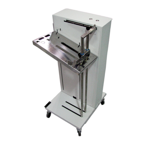
Page 1: Output Stacker
HIGH CAPACITY OUTPUT STACKER for the Mach 8 (AS-1180C M8 STK) SERVICE MANUAL Rev 09-17-14... -
Page 2: Safety Precautions
In addition, follow any specific occupational safety and health standards for your workplace or area. This manual is intended solely for the use and information of Neopost USA, its designated agents, customers, and their employees. The information in this guide was obtained from several different sources that are deemed reliable by all industry standards. -
Page 3: Table Of Contents
TABLE OF CONTENTS TABLE OF CONTENTS Disassembly/Assembly Procedures Basic Disassembly Service Disassembly Procedures Rear Cover (Non-Operator Side) Top Cover Replacing 'STACK HEIGHT' Sensor Replacing 'UPPER LIMIT' Safety Switch Replacing 'LOWER LIMIT' Sensor Replacing 'LOWER LIMIT' Safety Switch Replacing the Control Board Replacing Power Supply Replacing Speed Control Assembly Replacing Motor Assembly and Drive Belt... -
Page 4: Disassembly/Assembly Procedures
DISASSEMBLY AND ASSEMBLY Disassembly/Assembly Procedures Basic Disassembly • Turn off Power • Disconnect Power Cord • Disconnect Interface Cable Service Disassembly Procedures WARNING! THE FOLLOWING DISASSEMBLY SHOULD ONLY BE DONE BY A QUALIFIED, TRAINED SERVICE REPRESENTATIVE. WARNING! ALWAYS POWER DOWN THE DEVICE BEFORE CONNECTING OR DISCONNECTING ANY WIRING HARNESSES OR CABLE CONNECTIONS TO AVOID SERIOUS SHOCK OR INJURY. -
Page 5: Rear Cover (Non-Operator Side)
DISASSEMBLY AND ASSEMBLY Rear Cover (Non-Operator Side) 1. Remove the Rear Cover: Disconnect the Interface Cable. Remove (1) screw just above the power switch and (2) screws at the top of the panel. 2. Remove (6) screws (3 per side) located along the sides of the Rear Cover. -
Page 6: Top Cover
DISASSEMBLY AND ASSEMBLY Top Cover 1. Remove the Rear Cover: Disconnect the Interface Cable. Remove (1) screw just above the power switch and (2) screws at the top of the panel. 2. Remove (6) screws (3 per side) located along the sides of the Rear Cover. -
Page 7: Replacing 'Stack Height' Sensor
DISASSEMBLY AND ASSEMBLY Replacing 'STACK HEIGHT' Sensor 1. Remove the Rear Cover: Disconnect the Interface Cable. Remove (1) screw just above the power switch and (2) screws at the top of the panel. Remove (6) screws (3 per side) located along the sides of the Rear Cover. -
Page 8: Replacing 'Lower Limit' Sensor
DISASSEMBLY AND ASSEMBLY Replacing 'LOWER LIMIT' Sensor 1. Remove the Rear Cover: Disconnect the Interface Cable. Remove (1) screw just above the power switch and (2) screws at the top of the panel. Remove (6) screws (3 per side) located along the sides of the Rear Cover. -
Page 9: Replacing The Control Board
DISASSEMBLY AND ASSEMBLY Replacing the Control Board 1. Remove the Rear Cover: Disconnect the Interface Cable. Remove (1) screw just above the power switch and (2) screws at the top of the panel. Remove (6) screws (3 per side) located along the sides of the Rear Cover. 2. -
Page 10: Replacing Speed Control Assembly
DISASSEMBLY AND ASSEMBLY Replacing Speed Control Assembly 1. Remove the Rear Cover: Disconnect the Interface Cable. Remove (1) screw just above the power switch and (2) screws at the top of the panel. Remove (6) screws (3 per side) located along the sides of the Rear Cover. -
Page 11: Replacing Motor Assembly And Drive Belt
DISASSEMBLY AND ASSEMBLY Replacing Motor Assembly and Drive Belt 1. Remove the Rear Cover: Disconnect the Interface Cable. Remove (1) screw just above the power switch and (2) screws at the top of the panel. Remove (6) screws (3 per side) located along the sides of the Rear Cover. -
Page 12: Maintenance
MAINTENANCE Maintenance This section describes maintenance that an experienced operator can perform. If any service or maintenance is required beyond that which is described in this document, please contact your local dealer. Cleaning WARNING! THE OUTPUT STACKER IS A PRECISION MACHINE THAT SHOULD BE CLEANED REGULARLY TO INSURE MANY YEARS OF SERVICE. -
Page 13: Lubricating
MAINTENANCE Lubricating Before lubricating the Threaded Rod and Wheel Guides on the OUTPUT STACKER it is a good idea to wipe the surfaces to clean off any accumulated grit and dirt. 1. Removing the Rear Cover: Disconnect the Interface Cable. Remove (1) screw just above the power switch and (2) screws at the top of the panel. -
Page 14: Specifications
Specifications High Capacity Output Stacker Automatic when connected to MACH 8 Printer OPERATING MODES: Semi-automatic when used with other printers and/or printing equipment STACKER Up to 5,000 single sheets of 20 lb. (about 75g/m2) paper (10 reams) CAPACITY: MATERIAL Minimum: 3.5" W x 5" L (89 mm x 127 mm) Maximum: 9"... -
Page 15: Wiring Diagrams
WIRING DIAGRAMS Wiring Diagrams 115V Output Stacker... -
Page 16: 220V Output Stacker
WIRING DIAGRAMS 220V Output Stacker... - Page 17 Copyright © Neopost USA 2014...
Need help?
Do you have a question about the Mach 8 and is the answer not in the manual?
Questions and answers