
Related Manuals for Dräger FG7000


Summary of Contents for Dräger FG7000
- Page 1 Operating Instructions Dräger FG7000 Dräger MSI GmbH Rohrstraße 32 58093 Hagen Tel.: +49 2331 958 40 Fax: +49 2331 95 84 29 Email: msi.info@draeger.com 5695061 Edition 01 – April 2016...
-
Page 2: Table Of Contents
Operating Instructions Dräger FG7000 Contents 1. Information ........................3 1.1 Warning signs ......................3 1.2 For your safety ......................3 1.3 Safety instructions and warnings ................4 1.4 Bluetooth ........................4 1.5 Disclaimer ........................5 1.6 Maintenance and servicing ..................5 1.7 Disposal ........................ - Page 3 Operating Instructions Dräger FG7000 9.4 Leak test ........................22 9.4.1 Calculation of the gas pipe volume ..............22 9.4.2 Starting the serviceability test ................23 9.4.3 Result of the serviceability test................23 10. Checklists ........................24 11. Data memory ....................... 24 11.1 Saving measurements ....................
-
Page 4: Information
Operating Instructions Dräger FG7000 1. Information The manufacturer of this product, Dräger MSI GmbH, is referred to as Dräger MSI in the following. The displays shown in this manual are examples! 1.1 Warning signs Symbol Text Warning Indication of a potential dangerous situation. Avoiding this warning can lead to death or severe injuries. -
Page 5: Safety Instructions And Warnings
Operating Instructions Dräger FG7000 1.3 Safety instructions and warnings • Do not operate the product if there is damage to the housing, power supply or supply lines. Mark the product, to protect it against further use. • Do not conduct any measurements, which could lead to contact with uninsulated, hot parts. -
Page 6: Disclaimer
Operating Instructions Dräger FG7000 1.5 Disclaimer Dräger MSI does not assume any liability or warranty for damages or consequential damage arising from non-compliance with technical regulations, instructions and rec- ommendations. Dräger MSI and the sales companies are not liable for costs or dam- ages resulting from the use of the product by the user or third parties, especially in the case of improper use of the product. -
Page 7: Application
The service life of the sensors used in the Dräger FG7000 is typically 4 years for the O2, CO and NO sensor. The pressure sensor has no limited service life under normal conditions of use. -
Page 8: The Product
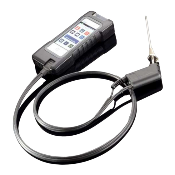
Operating Instructions Dräger FG7000 3. The product 3.1 The measuring device Gas conditioning USB port Illuminated display with touchscreen Charge control, IR transmitter On/Off button Connection external sensor Pressure ports P+ and P- Connection for combo-plug on the exhaust probe 5695061 Edition 01 –... -
Page 9: The Flue Gas Probe
Operating Instructions Dräger FG7000 3.2 The flue gas probe Combo-plug green LED yellow LED The green LED indicates the exhaust probe being ready for measurement. The yellow LED lights up when the highest temperature in the exhaust pipe is measured. It starts blinking when moving away from the spot with the highest temperature. -
Page 10: First Time Use And Operation
Prior to each measurement, make sure that a clean filter is inserted in the gas conditioner! Only turn the Dräger FG7000 on, if the flue gas probe has fresh air. The zero signals of the sensors are synchronized with the fresh air. -
Page 11: Switching On / Off
Operating Instructions Dräger FG7000 4.2 Switching on / off Switch on: Briefly press the On/Off button . The device switches on. When switching the device on for the first time, please select your lan- guage. When the start screen is activated, it displays the model and a logo. -
Page 12: Buttons
Operating Instructions Dräger FG7000 4.3 Buttons Menu = opens the context menu for the selection and editing of system data Select = enables the marked position = confirms a selection Done = leads to the next step of a function after an action... -
Page 13: Customer And System Management
Operating Instructions Dräger FG7000 4.4 Customer and system management The Menu button opens a context menu. Depending on the menu item, the context menu offers various editing options and commands. Customer data and comments can be entered via an on-screen keyboard. -
Page 14: Documentation Menu
Operating Instructions Dräger FG7000 4.6 Documentation menu After completion of a measurement, the documentation menu can be accessed. If no customer was selected before the measurement, a customer can be selected here using Customer or a new customer can be created. -
Page 15: Selecting And Entering Customer Data
Operating Instructions Dräger FG7000 6. Selecting and entering customer data Customers and system data sets can be created and edited under the Customer menu item. Conducted measurements can then be saved under the created customers and systems. Customers and systems can also be created after the measurement using a link in the docu- mentation menu. -
Page 16: Flue Gas Measurements
7.2 Starting the flue gas measurement. Switch on the Dräger FG7000, wait for system check to be completed and select Flue gas. If the pump was switched off prior to selecting the flue gas measurement function, a brief stabilization phase follows 7.3 Selecting fuels, heat carrier temperature... -
Page 17: Measuring Combustion Air Temperature
Operating Instructions Dräger FG7000 7.4 Measuring combustion air temperature If a separate combustion air sensor is not being used, the combustion air data must be measured using the flue gas probe prior to the flue gas measurement. This menu item can be skipped in the case of a flue gas measurement using a separate combustion air sensor. -
Page 18: Average Measurement
Operating Instructions Dräger FG7000 7.5.1 Average measurement The 1st Federal Immission Control Ordinance (BImSchV) requires the simultaneous determination of oxygen content of the exhaust and ex- haust temperature as an average value for a duration of 30 seconds. Insofar as the BImSchV measurement was activated in the settings, you can start the 30-second averaging process using Start;... -
Page 19: Quick Menu
CO con- centration in the ambient air. For the CO ambient air measurement the Dräger FG7000 doesn’t need a separate CO sensor. At a location with fresh air, without CO content, the value has to be 0 ppm. If the reading is not 0 ppm, pull off the Combo-plug of the gas probe from the device, wait for a short while and press Null. -
Page 20: Flue Gas Analysis Quick
Operating Instructions Dräger FG7000 8.4 Flue gas analysis quick The flue gas analysis quick allows to display only measured values without fuel selection and no fuel depending calculations. Displayed values: flue gas temperature, measured oxygen, measured carbon monoxide, measured nitrogen monoxide (option), measured induced draft, and determined combustion air ratio. -
Page 21: Pressure Measurements
Operating Instructions Dräger FG7000 9. Pressure measurements 9.1 Connection diagram Connect the metering point with the pressure inlet P+ on the measuring device using the burner pressure hose for pressure measurements up to a max. of 160 mbar (gas, nozzle or kinetic pressure). -
Page 22: Edition 01 – April
Operating Instructions Dräger FG7000 The test pressure can be adjusted between 20 and 25,000 mbar for tightness tests, the stabilization time and the measurement time be- tween 5 minutes and 6 hours. Optionally available high pressure sen- sors must be used for pressures exceeding 150 mbar. -
Page 23: Leak Test
No serviceability = amount of gas leakage > 5 l/h A semi-automatic serviceability test with air can be conducted with the FG7000 in accord- ance with the German Technical and Scientific Association for Gas and Water (DVGW) TRG1 2008 G600 Appendix 4 on gas lines with 23 mbar operating pressure. -
Page 24: Starting The Serviceability Test
Operating Instructions Dräger FG7000 9.4.2 Starting the serviceability test Increase the pressure in the gas line to 50 mbar with a hand pump via a valve. Then, close the valve on the pump and start the measurement. The measurement is automatically started after a stabilization phase of 30 sec. -
Page 25: Checklists
Operating Instructions Dräger FG7000 10. Checklists Measurement specifications often include visual inspections and other examinations. Such additional information regarding the measurements or the equipment can be recorded with checklists. Even work instructions can be created and processed in this manner. -
Page 26: Data Memory Functions
Operating Instructions Dräger FG7000 11.2 Data memory functions Selectable functions are: Measurement data: Saved measurement data indicates Info: Data storage information Inspector table: Viewing and editing the inspector table Delete measurements: Delete measurement data storage Delete customers: Delete all customer data 11.3 Measurement data... -
Page 27: Inspector Table
Operating Instructions Dräger FG7000 11.5 Inspector table Various inspectors with inspector numbers, name, street, postal code, city and telephone number can be entered in the inspectors table. The selected inspector is linked with the saved measurement data set. The selected inspector remains selected even after switching off the device. -
Page 28: Device Information
12. Device information This function provides information about the measuring device model (FG7000), the serial number of the measuring device, the version of the measuring device software (here 1.0,019), the measurement version, the manufacturer Dräger MSI GmbH, the selected inspector, the next scheduled maintenance, the set date and time. -
Page 29: Date And Time
Operating Instructions Dräger FG7000 13.1 Date and time Setting and changing date and time. Enter the desired date and time using the numeric keypad. Switch to the positions you would like to change using the arrow keys << / >>. -
Page 30: Start Screen
Operating Instructions Dräger FG7000 13.7 Start screen Turning the start screen on and off. When the device is switched on, the start screen appears with your company logo. The company logo can be uploaded to the device via the PC measurement data manage- ment. -
Page 31: Start Information
Operating Instructions Dräger FG7000 13.13 Start information This function can be used to turn the information display after the start screen on and off. 13.14 Printer footer texts With this feature, the printer footer text for the infrared printer can be changed line by line. -
Page 32: System Messages
Operating Instructions Dräger FG7000 14. System messages When being switched on and during measuring mode, the measuring device checks for proper functioning. System messages are shown af- ter the start-up phase and during normal functioning. Message Problem Corrective O2 sensor Probe was in the exhaust duct. -
Page 33: Power Supply
Operating Instructions Dräger FG7000 15. Power supply 15.1 General power supply information A chargeable lithium-ion battery installed in the measuring device enables mains-independ- ent operation. The operating time with fully charged battery is up to 8 hours; this can vary depending on the type of measurements and the brightness set for the display. -
Page 34: Technical Specifications
Operating Instructions Dräger FG7000 16. Technical specifications 16.1 General technical specifications Display: Colour display with touchscreen Interfaces: USB, IR Power supply: Li-ion battery, 3.6 V, 3400 mAh, charge level indicator, primary charger 100 - 240 V AC; secondary 5 V DC; 1 A... -
Page 35: Technical Specifications Exhaust And Pressure Measurements
Operating Instructions Dräger FG7000 16.2 Technical specifications Exhaust and pressure measurements Display Metering range Resolution Accuracy Combustion air - 10 … + 100°C 0.1 °C ± 1 °C temperature Exhaust gas tem- 0 … + 600 °C 0.1 °C (< 100 °C) ±... -
Page 36: Pc Measurement Data Management
Operating Instructions Dräger FG7000 17. PC measurement data management Please go to our website www.draeger-msi.de to download the measurement data manage- ment. You can find the measurement data management software PC200P, which you can download after a brief registration with your device number and your address data under the menu item Services→Downloads→FG7000→Software. -
Page 37: Edition 01 – April
Operating Instructions Dräger FG7000 5600813 ½” adapter with quick coupling 5600842 Single-pipe cover (≤ 3.5 bar) with quick coupling 5600880 Hand pump 5695061 Edition 01 – April 2016...
Need help?
Do you have a question about the FG7000 and is the answer not in the manual?
Questions and answers