
Subscribe to Our Youtube Channel
Related Manuals for Dräger REGARD


Summary of Contents for Dräger REGARD
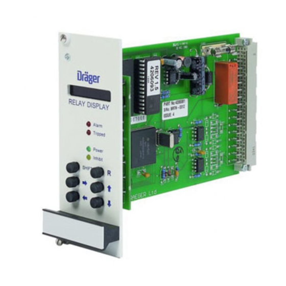
- Page 1 REGARD GAS DETECTION SYSTEM RELAY MODULE RELAY DISPLAY CARD (ATEX VERSION) 012:ALRM RELAY DISPLAY Alarm Tripped Power Inhibit SHIFT INSTRUCTIONS FOR USE...
-
Page 3: Table Of Contents
REGARD Relay Module & Relay Display Card (ATEX version) CONTENTS Page FOR YOUR SAFETY ....................... 4 Safe operation........................ 4 CE marking and ATEX marking..................5 Special conditions for safe use ..................5 OPERATION..........................6 Intended use........................6 Description ........................6 Operational fault relay .................. -
Page 4: For Your Safety
REGARD Relay Module & Relay Display Card (ATEX version) FOR YOUR SAFETY Follow the instructions Follow the instructions for installation, operation and maintenance. Use in areas subject to explosion hazards The relay module and relay display card are not designed for use in a flammable atmosphere without suitable protection. -
Page 5: Ce Marking And Atex Marking
REGARD Relay Module & Relay Display Card (ATEX version) CE marking and ATEX marking Regard cards and modules are CE marked to indicate conformity with the essential requirements of the “ATEX” Directive 94/9/EC: 0518 The number after the CE mark is the number of the Notified Body involved the production control phase. -
Page 6: Operation
REGARD • Additional common and voted alarm relays for a system comprising any combination of channel cards. • A1, A2, A3 and/or Fault relays for each channel of a Regard HART card or eight- channel display card. NOTE Neither A3 alarms nor use with the Regard 'HART' card are included in the scope of the EC-type examination certificate DMT 02 ATEX G 002 X. -
Page 7: Display Card Front Panel Controls And Indicators
REGARD Relay Module & Relay Display Card (ATEX version) Display card front panel controls and indicators Display Display normally shows the state of each alarm relay in sequence. When a relay is in its alarm state, only relays in alarm are displayed. -
Page 8: Controls
REGARD Relay Module & Relay Display Card (ATEX version) Controls Function of front panel controls during normal operation: Push button Result Note Display relay latch mode E.g. 001:LACK Display relay energise mode E.g. 023:ENER Display relay operating mode E.g. 002:SA1... -
Page 9: Relays Configured "Single" And "Lnak
REGARD Relay Module & Relay Display Card (ATEX version) Alarm is acknowledged while alarm condition is still present Setting Alarm trips Reset pressed Alarm clears Reset pressed DNAK Relay trips Alarm acknowledged Relay clears No effect Relay stays tripped LNAK... -
Page 10: Operational Faults
REGARD Relay Module & Relay Display Card (ATEX version) Operational faults An operation fault is a failure in the operation of either the relay display card or the relay module. Operational faults are either: • critical – card may stop working, or •... -
Page 11: Warning - Fault C Indication On The Relay Display Card
REGARD Relay Module & Relay Display Card (ATEX version) In the situation where multiple faults occur consecutively, the first fault to occur will be displayed. When that is cleared subsequent faults may be displayed if they are unaffected by the clearing of prior faults. -
Page 12: Installation
Handle circuit boards with care during installation. Do not touch the circuit boards or components. Use of the relay modules and relay display card requires a Regard master card. All Regard channel cards (e.g. 4-20, Ex, HART, 8-channel) must be connected to the same RS-485 bus as the relay display card and the master card. - Page 13 REGARD Relay Module & Relay Display Card (ATEX version) • Connect “A” on relay module to “A” on relay display card (terminal 11 on Regard rack) • Connect “B” on relay module to “B” on relay display card (terminal 10 on Regard...
- Page 14 REGARD Relay Module & Relay Display Card (ATEX version) Allowed connection arrangements “Bus” RELAY DISPLAY CARD MAXIMUM CABLE LENGTH: 1000m “Bus” with “stubs” • Maximum allowed length of a stub is 5m <5m RELAY DISPLAY CARD <1000m <5m RELAY DISPLAY CARD <1000m...
-
Page 15: Set Module Numbers
REGARD Relay Module & Relay Display Card (ATEX version) Disallowed connection arrangements “Star” – NOT ALLOWED RELAY MODULE RELAY MODULE RELAY DISPLAY RELAY MODULE CARD RELAY MODULE “Tree” – NOT ALLOWED RELAY MODULE RELAY DISPLAY RELAY MODULE CARD RELAY MODULE Set module numbers Set the ID number of each module using the rotary switch (SW1) on the module. -
Page 16: Connect Equipment To Relay Terminals
REGARD Relay Module & Relay Display Card (ATEX version) Connect equipment to relay terminals Normally-open and normally-closed contacts are labelled on the relay module. Labels show function of relay when de-energised: EMC! Use screened cable for connections to relays Connect DC supply to modules Connect 24V DC supply to terminals marked 24V and 0V. -
Page 17: Optional Connections
REGARD Relay Module & Relay Display Card (ATEX version) Optional connections Remote reset If required, connect normally-open contact to remote reset terminals on relay display card to allow remote reset of alarm relays. Connect using screw terminals on Regard rack. EMC! Use screened cable. -
Page 18: Switch-On And Initial Checks
REGARD Relay Module & Relay Display Card (ATEX version) Switch-on and initial checks Switch on DC supply to the relay display card and the relay module(s). Check that the Power LED on the relay display card and relay modules are lit. -
Page 19: Configuration
REGARD Relay Module & Relay Display Card (ATEX version) CONFIGURATION Command mode Configuration and maintenance of the display card is performed using front panel controls and display, by setting the card into command mode. Command mode is entered by pressing and holding the Reset button for about 5 seconds. -
Page 20: Table Of Commands
REGARD Relay Module & Relay Display Card (ATEX version) Table of commands Command Function Command mode level Default name Read Maint. Config. setting • • • 00–0 CMD QUIT Quit command mode • • • 00–1 PASSWORD Enter password •... -
Page 21: Configure Channel Cards And Master Card
Before configuring relay display card ensure that the other components of the Regard system are correctly configured: • Set operation of Regard master card and channel cards (4-20, Ex, HART, 8- channel, etc.) • Regard Master card must be configured to communicate with all channel cards that will control alarms on relay module(s). -
Page 22: Configuration Sequence
REGARD Relay Module & Relay Display Card (ATEX version) Configuration sequence Enter configuration-level password Factory-set configuration password is CCCC. PRESS DISPLAY 00–1 PASSWORD • Select 00–1 00-1 • Enter command PASSWORD then Ready for password entry ???? • Select first letter of password C??? •... - Page 23 REGARD Relay Module & Relay Display Card (ATEX version) Set function of relays PRESS DISPLAY 11–4 RLY MODE • Select 11-4 11-4:001 • Enter RLY MODE then Current setting: 001:NOP Relay number Function • Select function e.g. CA1 001:CA1 If SA1, SA2, SA3 or SF function selected, extra step required (see below) •...
- Page 24 REGARD Relay Module & Relay Display Card (ATEX version) Set voting configuration For relays configured voting (i.e. VA1, VA2, VA3 or VF), use command 11–1 to set voting information for each relay. Example 2 out of 3 voting for channels 4, 6 and 9.
- Page 25 REGARD Relay Module & Relay Display Card (ATEX version) Set relay latch/acknowledge operation Determines the operation of a relay when the alarm condition clears or when the relay alarm is acknowledged. WARNING – when a relay latch mode is set to ACK or LACK, a tripped relay can be cleared even though an alarm condition may still be present.
- Page 26 * NORM = Normally energised ENER = Energise on alarm Set communications checksum The relay display card must use the same communications checksum for RS-485 communications as the rest of the Regard system. Use CRC whenever possible. PRESS DISPLAY 52-6 CHECKSUM •...
-
Page 27: Optional Configuration Settings
REGARD Relay Module & Relay Display Card (ATEX version) Optional configuration settings Set relay display card number To allow remote configuration, each relay display card must be assigned a unique card number. Note: This setting allows differentiation of relay display cards on the same RS-485 bus by remote configuration software. -
Page 28: Maintenance
REGARD Relay Module & Relay Display Card (ATEX version) MAINTENANCE Recommended maintenance intervals EN 50073 and respective national regulations should be observed. Daily: • Visual check to determine readiness for operation At regular intervals: • Inspection by trained personnel. The inspection intervals in each individual case are subject to technical safety considerations, engineering processes and the technical requirements for the equipment. -
Page 29: Commands For System Maintenance
REGARD Relay Module & Relay Display Card (ATEX version) Commands for system maintenance Change password • Factory-set maintenance password is MMMM. • Factory-set configuration password is CCCC. • To change Configuration-level password, use command 00–3 after entering existing Configuration-level password •... - Page 30 REGARD Relay Module & Relay Display Card (ATEX version) Test LEDs and display 14-0 LED TEST PRESS DISPLAY • Select 14-0 14-0 • Press R to test LED TEST LEDs and display flash • Press R to stop 14-0 Test remote reset 14–1 RMT TEST...
- Page 31 REGARD Relay Module & Relay Display Card (ATEX version) Test relay module relay 14–4 RLY TEST PRESS DISPLAY • Select 14-4 14-4:001 • Enter RLY TEST then If relay not energised 001:OFF If relay energised 001:ON • Change relay state 001:ON •...
- Page 32 REGARD Relay Module & Relay Display Card (ATEX version) Disable relay(s) Each relay on the relay modules can be prevented from changing state when an alarm occurs. If a relay that is in its alarm state is disabled, the relay will change to its non-alarm state upon exit from command mode.
-
Page 33: Technical Data
REGARD Relay Module & Relay Display Card (ATEX version) TECHNICAL DATA Relay display card Supply voltage 18 to 35V DC Environmental operating range • –20° to +55°C Temperature • 0 to 90%RH, non-condensing Humidity • To BS 2011 Part 2.1Fc... -
Page 34: Ec-Type Examination Certificate
REGARD Relay Module & Relay Display Card (ATEX version) EC-Type Examination certificate Issue 1 – July 2003... - Page 35 Relay module configuration sheet Card No. Module No. 1 Relay No. Mode (11-4) Voting (11-1) Latching (11-7) Energise (04-4) Card No. Module No. 2 Relay No. Mode (11-4) Voting (11-1) Latching (11-7) Energise (04-4)
- Page 36 Relay module configuration sheet (contd.) Card No. Module No. 3 Relay No. Mode (11-4) Voting (11-1) Latching (11-7) Energise (04-4) Card No. Module No. 4 Relay No. Mode (11-4) Voting (11-1) Latching (11-7) Energise (04-4)
- Page 37 Relay module configuration sheet (contd.) Card No. Module No. 5 Relay No. Mode (11-4) Voting (11-1) Latching (11-7) Energise (04-4) Card No. Module No. 6 Relay No. Mode (11-4) Voting (11-1) Latching (11-7) Energise (04-4)
- Page 38 Relay module configuration sheet (contd.) Card No. Module No. Relay No. Mode (11-4) Voting (11-1) Latching (11-7) Energise (04-4) Card No. Module No. Relay No. Mode (11-4) Voting (11-1) Latching (11-7) Energise (04-4)
- Page 40 Draeger Safety UK Ltd Draeger Safety, Inc. Kitty Brewster Industrial Estate 10450 Stancliff Blyth Suite 220 Northumberland Houston, TX 77099 NE24 4RG U.S.A. England Tel. +1 281 498 1082 Tel. +44 1670 352891 +1 281 498 5190 +44 1670 356266 Dräger Safety AG &...
Need help?
Do you have a question about the REGARD and is the answer not in the manual?
Questions and answers