Table of Contents
Advertisement
Quick Links
Advertisement
Table of Contents

Subscribe to Our Youtube Channel
Related Manuals for PXM PX254


Summary of Contents for PXM PX254
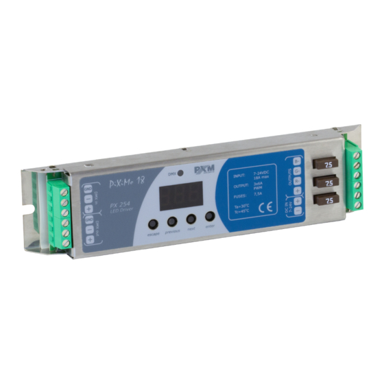
- Page 1 PX254 LED driver 3x6A/OC User manual...
-
Page 2: Table Of Contents
Table of Contents 1 Description....................4 2 Safety conditions..................5 3 Connector and control elements.............6 4 Designation of displayed messages............6 5 Button features...................8 6 Group DMX address settings..............8 7 Individual DMX address settings.............9 8 Colour settings mode................10 9 No DMX signal response................13 9.1 Description of programs..................15 10 Master / Slave function................16 11 White balance..................18... - Page 3 Manufacturer reserves the right to make modifications in order to improve device operation. PXM Marek Żupnik sp.k. Podłęże 654 tel. +48 12 385 83 06 32-003 Podłęże mail: info@pxm.pl Rev.2-4 BDO register number 000005972 www.pxm.pl 29.11.2018...
-
Page 4: Description
(R, G, B) directly with the DMX protocol. Wide range of power supply voltage and high current carrying capacity outputs (6A) permit a control of large quantities of LEDs. What is more the PX254 has built-in fuses that can be replaced by the user by himself. -
Page 5: Safety Conditions
The PX254 is produced in common anode version – it allows LEDs connection on common anode. Safety conditions PX254 LED Driver 3 x 6A OC is a device powered with safe voltage 7 – 24V; however, during its installation and use the following rules must be strictly observed: 1. -
Page 6: Connector And Control Elements
8. The device cannot be turned on in places with humidity exceeding 90%. 9. The device cannot be used in places with temperature lower than 2°C or higher than 40°C. 10. Clean with damp duster only. Connector and control elements control outputs DMX-512 input display... - Page 7 control method selection (RGB, Lightness / Colour, etc.) no DMX signal response method selection Master / Slave mode settings Lightness / Colour control mode RGB control mode RGB Dimmer control mode RGB Shutter control mode HSL control mode – Hue / Saturation / Lightness effect control mode dynamic white mode all outputs at 100%...
-
Page 8: Button Features
– enters the next MENU level and confirms changes made Group DMX address settings The menu of the PX254 driver allows for setting the DMX address within a range between 1 and 506 – 511 depending on work mode of device. -
Page 9: Individual Dmx Address Settings
ENTER NEXT Individual DMX address settings The PX254 module has an option that allows for changing individual settings. It enables assigning any DMX address to every output channel. The simplest example of implementation of this function is to control the lightness of one-color LEDs connected to all outputs. -
Page 10: Colour Settings Mode
ENTER ENTER NEXT ENTER NEXT The PX254 driver can operate in different control modes. NEXT Depending on the selected mode, the devices takes up a different numbers of channels, possible modes: NEXT The HSL mode (Hue, Saturation, Lightness) operates on three... - Page 11 Example: where 1 means the outputs are on and 0 are off The 3b mode (3-channel, 3-byte) each color (R, G, B) can be set separately The 2b mode (2-channel, 2-byte) consists in selecting lightness and one of the 256 colors define by the manufacturer The dW –...
- Page 12 Description guide of EFF mode settings CHANNEL CHANNEL CHANNEL CHANNEL CHANNEL CHANNEL CHANNEL 7 1 RED 2 GREEN 3 BLUE 4 MODE 5 SPEED 6 FADE BRIGHTNESS <0–7> Program 1 <8–15> Program 2 <16–23> Program 3 <24–31> Program 4 <32–39> Program 5 <40–47>...
-
Page 13: No Dmx Signal Response
Channel 1 – red colour Channel 2 – green colour Channel 3 – blue colour Channel 4 – operating mode selection Channel 5 – speed settings (higher value – quicker changes) Channel 6 – fade settings (higher value – smoother transition) Channel 7 –... - Page 14 ENTER ENTER ENTER 2 x NEXT NEXT PREV ENTER NEXT ENTER NEXT NEXT ENTER NEXT NEXT NEXT P01 – P18 – choosing a ready program provided in the device software. For each program it is possible to set the speed (SPd) of the effects reproduction on range 0,1 –...
-
Page 15: Description Of Programs
9.1 Description of programs The following tables show the values for each output channel (R, G, B) in programs from 1 up 18 (P01 – P18). The value 255 corresponds to the maximum lightness level on a given channel, 127 – 50% of power level, 0 –... -
Page 16: Master / Slave Function
Step 4 10 Master / Slave function The PX254 module has a built-in DMX-512 receiver and can be controlled from any desktop or controller running in this standard. Moreover, it is equipped with a programmable function of response to no DMX signal (noS). - Page 17 With this solution, it is possible to make a precise synchronization even in very large installations without using an external controller. ENTER ENTER 3 x NEXT ENTER ENTER NEXT NEXT Con – turning on or turning oFF Master feature Chn – the number of DMX channels sent ENTER NEXT...
-
Page 18: White Balance
Sometimes, there can be problems with getting white colour on the RGB series LEDs. This may be a result of using diodes with different technical parameters. For this reason, the PX254 module is equipped with a white balance function. This option allows for choosing a correct colour temperature for full activation of all 3 outputs (white colour). -
Page 19: Limiting The Output Power
12 Limiting the output power The white balance parameter, apart from its original functionality, can also be used to limiting the output power of the driver. It works linearly and in a percentage way limits the output power of a given channel. For example, if the bLr parameter is set on 50, it means that by the DMX control and no signal mode this value can not be exceeded. -
Page 20: Smooth
13 Smooth The driver is equipped with a smooth option. Smooth feature allows for smooth changes in lightness and colour. When it is set to On the transition between successive DMX values sent to the lamp (e.g. corresponding to changes in lightness) are smooth with no visible twitches, which prevents the common light “vibrations”... -
Page 21: Light Control Frequency
ENTER ENTER 5 x NEXT ENTER NEXT NEXT PREV ENTER NEXT 14 Light control frequency The Frq function allows for setting the basic control frequency for the LEDs. This function is extremely useful in applications for the television industry. By applying the "flicker free" technology, it is possible to avoid the unpleasant flickering effect which is caused by improper signal synchronization that controls the LEDs. -
Page 22: Screen Saving (Screen Blanking)
The frequency value in the upper range (e.g. 1.50 = 1.5kHz) helps to avoid the flickering effects that are visible in video cameras. ENTER 2 x NEXT ENTER NEXT 15 Screen saving (screen blanking) The device is equipped with a feature that allows for turning off the backlight. -
Page 23: Restore Default Settings
In such a case, try to restore the device to its default settings before sending the PX254 to the service center. If, after restoring to its default settings, the device still does not operate correctly, please send it to our service center. -
Page 24: Error Message
16.2 Error message The device is equipped with a built-in memory work control function. If there are problems with the memory operation on the PX254 display, the Err message appears – memory error. In this situation, select the “enter” key. The device will reload the default configuration and upload it to the memory. -
Page 25: Dmx Signal Connecting
PX254 have to be connected to DMX line in serial mode, with no branches on DMX control cable. That means that DMX line, from the signal source, must be connected to DMX IN pins of PX254 and later, directly from DMX OUT pins to the next device in DMX chain. -
Page 26: Rdm - Available Parameters
19 RDM – available parameters The PX254 supports the DMX-RDM protocol. DMX protocol allows only of a one-way data transmission, while its extension the RDM protocol can transmit information in two directions. This makes possible to simultaneously send and receive information, and hence the possibility of monitoring activities of the compatible devices. - Page 27 Two states are possible: identification is off (0x00 value) and identification is on (0x01 value). STATUS_MESSAGES 0x0030 information about device status DEVICE_MODEL_ 0x0080 device description, e.g. name DESCRIPTION Parameter name Description manufacturer description, MANUFACTURER_LABEL 0x0081 e.g. name additional device description; It is possible to enter an additional DEVICE_LABEL * 0x0082...
- Page 28 OFF_21 * signal settings of red channel value SCENE_RED * 0x801D for scene saved in PX254 settings of green channel value SCENE_GREEN * 0x801E for scene saved in PX254 settings of blue channel value SCENE_BLUE * 0x801F for scene saved in PX254...
-
Page 29: Programming
* - editable parameter ENTER ENTER ENTER NEXT NEXT ENTER NEXT NEXT ENTER ENTER NEXT NEXT NEXT NEXT NEXT NEXT ENTER NEXT NEXT NEXT NEXT ENTER NEXT NEXT NEXT NEXT NEXT ENTER ENTER NEXT NEXT NEXT ENTER NEXT NEXT ENTER NEXT NEXT ENTER... -
Page 30: Connection Scheme
21 Connection scheme controller LED strip RGB INPUT: OUTPUT: max. 32 devices in DMX line power supply 7 - 24 V DC INPUT: OUTPUT: Terminator (Rezystor 120 Ohm connected between DMX+ and DMX-) Please note that the driver is common anode type device. It is possible to connect lamps with 4-wires cable with a common + only. -
Page 31: Dimensions
Sample connection of warm and cold white LEDs strips for Dynamic White mode warm white LED strip cold white LED strip INPUT: OUTPUT: power supply 7 - 24V DC With such a connection of strips, in dW control mode, the value 0 on the color temperature channel corresponds to warm white color, and value 255 –... -
Page 32: Technical Data
23 Technical data type PX254 DMX channels RDM protocol support power supply 7 – 24V DC max. current consumption 30mA for 12V DC power consumption without load 40mA for 24V DC output channel number control accuracy 16 bit programmable scenes... - Page 33 Podłęże, 29.11.2018 DECLARATION OF CONFORMITY PXM Marek Żupnik spółka komandytowa Podłęże 654, 32-003 Podłęże we declare that our product: Product name: LED driver 3x6A/OC Product code: PX254 meets the requirements of the following standards, as well as harmonised standards: PN-EN 50581:2013...
Need help?
Do you have a question about the PX254 and is the answer not in the manual?
Questions and answers