Table of Contents
Advertisement
Quick Links
Advertisement
Table of Contents

Related Manuals for PXM PX345+


Summary of Contents for PXM PX345+
- Page 1 PX345+ DMX Controller User manual...
-
Page 2: Table Of Contents
Table of Contents 1 Description....................4 2 Safety conditions..................5 3 Connectors and control elements............6 4 Screen and buttons..................7 4.1 Navigating the menu....................7 4.2 Main window........................ 8 4.3 Errors..........................8 4.4 Controller status......................8 4.4.1 Digital inputs....................... 9 4.4.2 DMX output......................9 4.4.3 Running scenes.................... - Page 3 9.6 Core mode, FTP support..................66 10 Connection scheme................67 11 Dimensions.....................70 12 Technical data..................70 Manufacturer reserves the right to make modifications in order to improve device operation. PXM Marek Żupnik sp.k. Podłęże 654 tel. +48 12 385 83 06 32-003 Podłęże mail: info@pxm.pl Rev.1-0 BDO register number 000005972 www.pxm.pl...
-
Page 4: Description
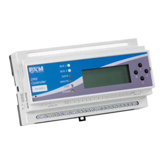
Description The PX345+ DMX Controller is an advanced architectural lighting controller that allows for controlling even the most complex lighting systems. With programmable functions, the device enables the control of lighting, multimedia, and other devices that are operated based on the DMX protocol. The controller has 1 DMX output line (128 channels) and it allows for triggering multiple configuration items at the same time. -
Page 5: Safety Conditions
Safety conditions PX345+ DMX Controller is a device powered with safe voltage 12 – 24V DC, however, during its installation and use the following rules must be strictly observed: 1. The device can be connected to 12 – 24V DC (stabilized voltage) with current-carrying capacity compatible with technical data. -
Page 6: Connectors And Control Elements
Connectors and control elements control keys Ethernet connector PX345+ PX Art signaling diodes 192.168.1.101 RUNNING PX345+ screen 01.10.2021 Fri 11:23 reset DMX output power supply on / off inputs 12 - 24V DC Sink / Source pin... -
Page 7: Screen And Buttons
Screen and buttons 4.1 Navigating the menu (escape) - allows to exit the parameter being programmed ✕ without saving any changes or to move to a higher menu level ↓ next) - scrolls the menu down or reduces the values to be ↑... -
Page 8: Main Window
4.2 Main window The start screen, which is visible after starting the device, contains: model and serial number of the device, its current IP address, status as well as date and time on the device. PX345+ 21320345 192.168.1.101 RUNNING 01.10.2021 Fri 11:23 Possible statuses are: •... -
Page 9: Digital Inputs
4.4.1 Digital inputs In the DIGITAL INPUTS menu, in the CONTROLLER STATUS tab, you can view the status of digital inputs: 16 internal (in). PX345+ 21320345 ERRORS (0) ENTER 192.168.1.101 CONTROLLER STATUS CLOCK RUNNING 01.10.2021 Fri 11:23 EVENTS NEXT ERRORS (0) DIGITAL INPUTS ENTER ENTER... -
Page 10: Running Scenes
4.4.3 Running scenes In the RUNNING SCENES menu on the CONTROLLER STATUS tab you can see which scenes are currently running. PX345+ 21320345 ERRORS (0) ENTER 192.168.1.101 CONTROLLER STATUS CLOCK RUNNING 01.10.2021 Fri 11:23 EVENTS NEXT ERRORS (0) DIGITAL INPUTS ENTER CONTROLLER STATUS DMX OUTPUT... -
Page 11: Clock
4.5 Clock In the CLOCK menu, you can read the current date, day of the week and time, in addition, the controller displays the SUNRISE and SUNSET times of the sun. ERRORS (0) PX345+ 21320345 ENTER CONTROLLER STATUS 192.168.1.101 RUNNING CLOCK 01.10.2021 Fri 11:23 EVENTS... -
Page 12: Channel Test
4.7 Channel test The TEST CHANNELS allows to drive ALL channels to the maximum value – 255. It is also possible to control individual channels. This option can be useful for testing the connection on the DMX line between the controller and the signal receiver. -
Page 13: Screen Settings
4.8 Screen settings LCD SETTINGS allows to change the brightness of the display, the values are expressed as a percentage (0%, 25%, 50%, 75%, 100%). In this menu, the user can enable the DARK MODE option, i.e. turning off the screen backlight after ~15 seconds of inactivity. -
Page 14: Pin Protection
4.8.1 PIN protection The device can be protected with a code, the function is activated in the LCD SETTINGS menu. Change the PIN option to On. The default PIN is 0 0 0 0. To lock the device, press and hold the esc button in the home screen. When the PIN code protection function is active, the padlock icon is displayed on the display in the main window. -
Page 15: Information About The Driver
4.9 Information about the driver Information about the controller are available in the CONTROLLER INFO tab, you can read: • serial number and MAC, firmware version, • configuration information. • ERRORS (0) PX345+ 21320345 ENTER CONTROLLER STATUS 192.168.1.101 RUNNING CLOCK EVENTS 01.10.2021 Fri 11:23 6 x NEXT... -
Page 16: Applications
4.11 Applications The APPLICATIONS menu allows to view the devices currently connected to the controller (PC / Smartphone / touch panel). ERRORS (0) PX345+ 21320345 ENTER CONTROLLER STATUS 192.168.1.101 CLOCK RUNNING 01.10.2021 Fri 11:23 EVENTS 8 x NEXT APPLICATIONS ENTER REBOOT 4.12 Restart The REBOOT tab in the menu includes the following options:... -
Page 17: Network Settings Of The Controller
LOGOUT ALL USERS – logout of all users currently connected to the • controller ERRORS (0) PX345+ 21320345 ENTER 192.168.1.101 CONTROLLER STATUS RUNNING CLOCK EVENTS 01.10.2021 Fri 11:23 9 x NEXT APPLICATIONS ENTER REBOOT ENTER REBOOT REBOOT FACTORY DEFAULTS Are you sure? RESET NETWORK LOGOUT ALL USERS NEXT... - Page 18 Thanks to this, manual configuration of networks parameters is not needed. In the absence of a DHCP server on the network the controller will operate according to the static configuration (manual setup). When choosing static addressing, the network parameters configure should be in such a way that the controller is able to operate on the subnet and there is no conflict of IP addresses (devices in the network must have unique IP addresses).
-
Page 19: Change Of The Computer Network Configuration
5.1 Change of the computer network configuration The procedure for changing the computer network configuration varies depending on the operating system. Windows ® 7 system is an example here. Change of the computer network configuration in the Windows ® 7 operating system in done in the following: 1. - Page 20 5. Right-click on the appropriate connection, for example it could be [Ethernet] and select [Properties] 6. In the new window that appears, select [Internet Protocol Version 4 (TCP/IPv4)] and then press properties...
- Page 21 7. In the next window, select [Use the following IP address:] To connect directly (computer – driver) with a controller that has a default configuration, use the sample settings: IP address: 192.168.0.51 Subnet mask: 255.255.255.0 Default gateway: 192.168.0.1...
-
Page 22: Connecting Controller Directly To The Pc
5.2 Connecting controller directly to the PC When connecting the controller directly to a computer it is recommended to use a braided cable. Newer network cards will work both on a braided cable or a non-braided cable, but older ones may require a braided cable. PX345+ Default configuration: IP: 192.168.0.50... -
Page 23: Automatic Addressing
5.3.1 Automatic addressing Below is a diagram of the operation of devices with the DHCP server running: Smartphone recives configuration Router on its own IP: 192.168.0.100 Mask: 255.255.255.0 DHCP: On PX345+ PX345+ Settings from DHCP DHCP: On DHCP: On... -
Page 24: Static Addressing
5.3.2 Static addressing Below is an example diagram of network settings of the controller and devices cooperating with it, in the case when the DHCP server in the network is not running: Smartphone IP: 192.168.0.3 Router Mask: 255.255.255.0 IP: 192.168.0.1 Gate: 192.168.0.1 Mask: 255.255.255.0 DHCP: Off... -
Page 25: Logging Into The Controller
Logging into the controller Logging into the controller is possible from the local network and from external network (Internet). In both cases, the device can be logged in from PC using the PxDesigner program to configure the device and PxMini from a mobile device via the PxMobile application (PxMini and PxMobile are used to control the controller), which already has to configured configuration. -
Page 26: Remote Logging (External Network)
6.2 Remote logging (external network) The controller allows you to log in to the device from an external network via the internet, for this purpose it should be: • have an external IP address on the router assigned by the internet provider and be able to establish connection from outside (incoming packets are not blocked by the provider’s and router’s firewall) redirect appropriate ports / port to the IP address of the controller... -
Page 27: Logging In Via The Pxdesigner Application
Most routers available on the market usually have several parameters in port forwarding options: forwarding number • • port or port range for redirection • the IP address of the device to be redirected to protocol type (TCP / UDP or both) •... - Page 28 Below is the screen of the example setting in the router: If there is no option to set the port range in the router, create two separate rules for each port separately (separately for 50000 and 50001). If everything is correctly configured to connect to the controller from the (external) internet network, in the application click Connect, then select the option Remote login and then in the IP field enter the IP address of the router (assigned by the internet provider, in this cane 66.77.88.99),...
- Page 29 The connection diagram is on the next page.
- Page 30 Router IP: 192.168.1.1 Mask: 255.255.255.0 DHCP: Off Redirecting port 50000 and 50001 to the device address (192.168.1.10) external IP address np. 66.77.88.99 PX345+ PX345+ INTERNET IP: 192.168.1.10 Mask: 255.255.255.0 Gate: 192.168.1.1 DHCP: Off internet connection...
- Page 31 b) more then one controller works in the local network with the following settings: external IP address: 66.77.88.99 (example address) • IP address of the first controller: 192.168.1.10 • IP address of the second controller: 192.168.1.11 • • mask: 255.255.255.0 target device port: 50000 and 50001 for the first controller, •...
- Page 32 The connection is exactly the same as in example 1, except that the ports 50000 and 50001 are for the first device, and the 60000 and 60001 are for the second device. Connection example: Router IP: 192.168.1.1 Mask: 255.255.255.0 DHCP: Off Port forwarding to appropriate IP addresses external IP address, e.g.:...
-
Page 33: Login From The Pxmini And Pxmobile Applications
6.2.2 Login from the PxMini and PxMobile applications The controller works in the local network with the following settings: • external IP address: 66.77.88.99 (example address) IP address: 192.168.1.10 • mask: 255.255.255.0 • target device port: 50002 • protocol: UDP or TCP/UDP (in this case option “Both”) •... - Page 34 If there is no option to set one port forwarding in the router, create a range (from 50002 to 50002). If everything is correctly configured to connect to the controller from the (external) internet network, select the Remote login in the application (PxMini or PxMobile), and then enter the User and Password of the user and Host (assigned by the internet provider, in this case 66.77.88.99), in the Port field enter the port number (50002).
-
Page 35: Software Installation
• of recording the disc) NOTE! All these files can be found on the manufacturer’s website (pxm.pl). The firmware update is recommended to be downloaded from the product page, as there is always the latest version of the device firmware update. - Page 36 1. Open an installation file, click [Next] to go to the software installation. The installation file is attached to the driver on a CD or available for download from the manufacturer’s page (pxm.pl). 2. Select the folder in which the software is to be installed. Confirm your selection by clicking the [Next] button.
-
Page 37: Android
7.2 Android™ The PxMobile application can be installed on Android™ 4.0 or later. To install software: 1. Upload *.apk installation file available on manufacturer’s page to the phone memory. 2. Go to phone settings and then check “Allow installation of apps from sourced other than The Play Store”... -
Page 38: Controller Configuration
Controller configuration The controller operates in accordance with the loaded configuration which is created and uploaded using the PxDesigner application. The method of creation of a configuration file is described in the manual for PxDesigner. As part of the configuration, it is possible to set the parameters for all inputs and outputs, create users and relevant configuration items. -
Page 39: Scenes
8.2 Scenes A scene is a set of values for all DMX output channels. Scene parameters: name • rise time • duration • drop time • • zone to which it belongs • group of associated items to which it belongs value for all DMX channels of the zone •... -
Page 40: Programs
8.3 Programs A program is a system of subsequent scenes along with a defined input time and duration. Program parameters: name • zone to which it belongs • number of repetitions / loop • • number of steps • event at the end of the program drop time of the last step •... -
Page 41: Shows
All times are multiplied by the current value of the “speed” parameter. The value of 1.00 is a neutral value and a default value. For 2.55 all the times are extended 2.5 times and for 00.1 the times are divided by 100. For the value of 0, all the times are shorten to the minimum value (0.01s) –... - Page 42 Program parameters: name • zone to which it belongs • group to which it belongs • duration • • number of repetitions / loop event at the end of the program • default master value • default value of speed •...
-
Page 43: Masks
The modes of merging elements in the show: covering • higher wins • alpha • light • • water color • brightness • white balance • • subtract • • multiplication mask • 8.5 Masks A mask is a set of values assigned to output channels, which modifies a value at the DMX output. - Page 44 There are 3 types of masks: proportional – it changes all values in the channel proportionally to the • values of the mask value mask channel 1 DMX output maximal – it converts all the values in the channel that are greater •...
- Page 45 Mask parameters: name • rise time • duration • drop time • • zone to which it belongs value for all DMX channels of the zone • type: • ◦ proportional ◦ minimum value ◦ maximum value If several masks are turned on at a time: from all the proportional masks turned on in the zone, the lowest value •...
-
Page 46: Sequences
8.6 Sequences A sequence is a set of successive steps, each of which may trigger several actions in parallel and take a set amount of time. Sequence parameters: name • number of steps • list of steps • ◦ step duration ◦... -
Page 47: Group Of Associated Items
8.8 Group of associated items Scenes, programs and shows can belong to different areas in one group of associated elements. Items that are associated cannot be run at the same time, which is why turning on an item belonging to a group turns off all other elements belonging to this group. -
Page 48: Events
An example of a value transition in a channel for non-associated items: value value value start time the beginning the beginning the end of time of fade in time of fade out time transition transition time 8.9 Events An event is the execution of a list of actions as a reaction to a specific signal. -
Page 49: Action Limitations
from ON /OFF inputs – two events assigned to each input: • ◦ rising edge ◦ trailing edge from multi-value inputs – (DMX input, analogue input, Modbus, PID) • depending on the settings of a given input – one or two events •... -
Page 50: Delay
While calculating the sunrise / sunset time, the movement of the sunrise / sunset entered by the user is taken into account. Status limitation – for each status an action can: • ◦ ignore its state ◦ start only if a status is set ◦... -
Page 51: Controller Operation
Controller operation The controller works in accordance with a preloaded configuration: in response to relevant events it executes the programmed actions that can turn on or off the selected configuration items. Triggering events and starting configuration elements is done in the master controller. Expansion modules only have additional DMX outputs. -
Page 52: Modbus
ON/OFF INPUTS SMART- PHONE OUTPUT CLOCK ASTRONO- MICAL CLOCK 9.2 Modbus The controller supports the Modbus TCP/IP protocol. A PX345+ controller operates as a server (slave), to which an application / a device operating as a client (master) connects. The master establishes a connection through TCP port 502 (a standard Modbus port) using the current IP address of the controller. - Page 53 Single packet: Single packet (ADU) MBAP Header Command Data Field Description Size MBAP Packet number – for purpose Transaction ID of simplification it can be equal to 0 For the Modbus protocol it is Protocol ID always equal to 0 The number of subsequent data (after Lenght this field) transmitted –...
- Page 54 Example 1: A query about 10 first DMX channels in hexadecimal notation reads as follows: 00 00 00 00 00 06 00 03 20 00 00 0A PDU explained: 03 – Modbus function code: 03, meaning “Read Holding Registers” 20 00 – address of the register being read – 0x2000 = 8192 – corresponds to DMX output channels 00 0A –...
- Page 55 Example 2: Writing a value of 255 to the first Modbus register. The controller will treat the register as a Modbus input channel. You can set the response of → the controller to a change of value in the channel in the tab “Input Modbus ”...
- Page 56 Example 3: Hexadecimal notation for a TCP frame that triggers scene No 1: 00 00 00 00 00 0B 00 45 01 00 00 00 01 00 00 00 00 00 00 00 00 00 07 00 45 01 00 00 00 01 PDU explained: 45 –...
- Page 57 Below there are presented Modbus commands supported by the controller: a) Commands Modbus command Controller reaction standard Read Coils not supported Read Discrete Inputs returns the state of digital inputs in bits 3 Read Holding Registers returns the status of the controller Read Input Registers returns the status of the controller Write Single Coil...
- Page 58 In the case of the “Write Single Register” command, the Modbus input is treated as a multi0value input with 512 channels. The parameters of each channel are set in the same manner as in the case of a DMX input. b) Returned states Element Size...
- Page 59 Element Size Description state Delay status data time left [ms] reserved state master speed Film status data (playing) repeat count current step reserved...
- Page 60 c) Actions Number Action Parameters no action scene number scene number scene number solo scene number toggle scene number Scene pause scene number resume scene number set master scene number master value increase master scene number decrease master scene number mask number mask number solo...
- Page 61 Number Action Parameters restart program number set master program number master value increase master program number decrease master program number Program set speed program number master value accelerate program number slow down program number next step program number previous step program number sequence number Sequence...
- Page 62 Number Action Parameters set master zone number master value increase master zone number Zone decrease master zone number off all zone number transmission on Modbus transmission off transmission on Analogue inputs transmission off film number film number solo film number toggle film number stop...
-
Page 63: Live Mode
d) Register addresses Addressing Size Data Read / write 0x0000 – 0x01FF Modbus “input” channels R / W 0x0400 – 0x05FF DMX input channels 0x0800 – 0x09FF analogue input channels 0x0C00 – 0x0FFF digital inputs 0x1400 – 0x15FF statuses 0x2000 – 0x23FF DMX output channels 0x4000 –... -
Page 64: Indication Lights
9.4 Indication lights The controller is quipped with 4 indicator lights: Indicator Action Function BUS 1 not used in PX345+ BUS 2 receiving data from a PC application or green DATA flashing smartphone information about shorting of one of green INPUTS single blink the digital inputs... -
Page 65: Reset Button Operation And Restoring Default Settings
9.5 RESET button operation and restoring default settings Action Reaction Holding down the button when Switching the device to the core the power supply is turned on mode Holding down the button for 2 Switching the device to the normal seconds when the device is operating mode in the core mode... -
Page 66: Core Mode, Ftp Support
9.6 Core mode, FTP support After switching to the core mode (stop in the bootloader), it is possible to connect the controller using the FTP protocol. In this mode, you should always connect to the default static address on the controller from the ADMIN account level, by providing the default password (device serial number) –... -
Page 67: Connection Scheme
The connection to the controller via FTP can be useful when it is not possible to upload the firmware update via the application. Then, replace the “UPGRADE.upg” file in the controller and exit the core mode (by force). The controller will be automatically updated. Using the FTP it is possible to delete the uploaded configuration. - Page 68 b ) connection of digital inputs (sink in) – positive logic input – “joint plus” inside the controller controller connectors e.g. input buttons 12 - 24V DC power supply...
- Page 69 c ) connection of digital inputs (source in) – negative logic input - “joint mass” inside the conteoller controller connectors e.g. input buttons 12 - 24V DC power supply...
-
Page 70: Dimensions
11 Dimensions PX345+ PX Art 192.168.1.101 RUNNING PX345+ 01.10.2021 Fri 11:23 12 Technical data type PX345+ power supply 12 – 24V DC power consumption max. 6W DMX output 1 (128 channels) control inputs (on / off) Ethernet port Real Time Clock (RTC) Modbus scenes and programs steps 251000... - Page 71 timers 1024 zones users (including ADMIN) weight 0.3kg width: 157mm (9 DIN rail modules) dimensions height: 86mm depth: 60mm...
- Page 72 Podłęże, 16.10.2021 DECLARATION OF CONFORMITY PXM Marek Żupnik spółka komandytowa Podłęże 654, 32-003 Podłęże we declare that our product: Product name: DMX Controller Product code: PX345+ meets the requirements of the following standards, as well as harmonised standards: PN-EN IEC 63000:2019-01...
Need help?
Do you have a question about the PX345+ and is the answer not in the manual?
Questions and answers