Table of Contents
Advertisement
Quick Links
Advertisement
Table of Contents

Related Manuals for PXM PiXiMo 18


Summary of Contents for PXM PiXiMo 18
- Page 1 PX282 PiXiMo 18 LED Driver 3 x 6A OC MANUAL...
-
Page 2: Table Of Contents
22. Technical specification......................23. Declaration of conformity..................... Manufacturer reserves the right to make modifications in order to improve device operation. tel.: +48 12 626 46 92 PXM Marek Żupnik spółka komandytowa fax: +48 12 626 46 94 ul. Przemysłowa 12 E-mail: info@pxm.pl 30-701 Kraków, Poland... -
Page 3: General Description
1. GENERAL DESCRIPTION The PX282 driver is designed to control LEDs. The device has been placed inside DIN rail housing. The built-in DMX receiver allows for activating 3 channels (R, G, B) by using directly the DMX protocol. A wide range of supply voltage and a high level of current-carrying capacity (6A) enable activating large quantities of LEDs. -
Page 4: Connections And Control Elements Description
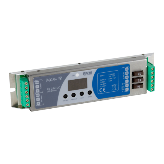
3. CONNECTIONS AND CONTROL ELEMENTS DESCRIPTION DMX IN DMX OUT www.pxm.pl PX282 R – G – B – DC IN OUTPUTS DMX-512 input Display DMX-512 output Programming keys Control outputs Power supply 4. DESIGNATION OF DISPLAYED MESSAGES DMX address of a device - a basic item in the MENU... - Page 5 all outputs off scene programme no. 17 DMX address settings for first channel MASTER mode on / off number of channels being sent in the MASTER mode white colour balance setting red balance green balance blue balance white colour balance on / off program playback speed level of steps change smoothness in the program colour...
-
Page 6: Dmx Address Settings
5. DMX ADDRESS SETTING The menu of the PX282 driver allows for setting the DMX address within a range between 1 and 506-511 depending on work mode of device. For example in RGB mode it occupies three consecutive DMX addresses. If start address is set to 510, the last channel is occupied by address 512. -
Page 7: White Balance
7. WHITE BALANCE Sometimes, there can be problems with getting white colour on the RGB series LEDs. This may be a result of using diodes with different technical parameters. For this reason, the PX282 module is equipped with a white balance function. This option allows for choosing a correct colour temperature for full activation of all 3 outputs (white colour). -
Page 8: Individual Settings
Description guide of EFF mode settings EFF mode (effect) channels desription CHANNEL1 CHANNEL2 CHANNEL3 CHANNEL5 CHANNEL6 CHANNEL7 CHANNEL4 – MODE GREEN BLUE SPEED FADE BRIGHTNESS < 0 7 > Program1 < 8 - 15 > Program2 < 16 - 23 > Program3 <... -
Page 9: No Dmx Signal Response
If you select the operating mode in the Cbn menu, which limits the number of channels in relation to the maximum value, an individual address out of the range cannot be programmed. For example, after selecting the 2b mode, a chosen value can be assigned only to addresses 1 and 2. -
Page 10: Description Of Programs
function - to change the rate of steps change, you need to confirm ”enter” on the tab of a program you are interested in. Then, click the „next” or „previous” buttons to set the FAd parameter. Then, press the enter button and enter a chosen value between 0 (abrupt transition) up to 100 (completely smooth transition) using the „previous”... -
Page 11: Light Control Frequency
12. LIGHT CONTROL FREQUENCY The Frq function allows for setting the basic control frequency for the LEDs. This function is extremely useful in applications for the television industry. By applying the "flicker free" technology, it is possible to avoid the unpleasant flickering effect which is caused by improper signal synchronization that controls the LEDs. -
Page 12: Smooth
14. SMOOTH The driver is equipped with a smooth option. Smooth feature allows for smooth changes in lightness and colour. When it is set to On the transition between successive DMX values sent to the lamp (e.g. corresponding to changes in lightness) are smooth with no visible twitches, which prevents the common light "vibrations"... -
Page 13: Default Settings And Memory Error (Err)
15. DEFAULT SETTINGS AND MEMORY ERROR (Err) The device has a built-in feature that allows for restoring default settings. To use this option, PX282 must be disconnected from the power supply. Before restoring the power, press and hold the „previous” button. After turning the device on, the message will appear on the screen (when turning on the power until displaying the previous message,... -
Page 14: Cpu Temperature
Below are examples of messages displayed by the device for overburdened individual channels, while the PX282 in the basic menu with address 1 ( ).Exceeding the load does not change on the rest of the segments of the display, they displayed earlier message unchanged. 1 channel is overloaded(r) 2 channel is overloaded(G) 3 channel is overloaded(b) In case of an overloading of all three channels at the same time a flashing message is... - Page 15 DMX_PERSONALITY - DMX working mode - PID: 0x00E0, Editable parameter. The selectable DMX work modes are listed below: 1) RGB mode (see item 9 of this manual) - a value of 1; 2) 2B mode (see point 9) - a value of 2; 3) RGBD mode (see point 9) - a value of 3;...
- Page 16 PROGRAM_SPEED - programs playback speed settings (playing next steps of program) - ź PID: 0x8023, Editable parameter. Minimum value is 1 and maximal 999 (maximum speed). By default it is set to 10. Value 1 represents 0,1s, and 999 - 99,9s; PROGRAM_FADE - settings of smooth transition between following steps of a program - ź...
-
Page 17: Programming
19. PROGRAMMING REMARKS: 1. ENTER allows for entering ENTER ENTER ENTER a subsequent "submenu" and saving NEXT a selected parameter. NEXT 2. ESCAPE allows for returning to the ENTER previous menu without saving changes. NEXT 3. NEXT allows for moving forward within the selected menu. -
Page 18: Connections Scheme
DMX+ PX015 DMX- Chaser Scene % 100 100 % to next modules Club 6p DMX IN DMX OUT www.pxm.pl PX282 12-24V DC power supply R – G – B – 12-24V DC OUTPUTS V- V+ typical LED strip Caution!! For power supply connection, use only cable of minimum 2.5 mm cross-section... -
Page 19: Dimensions
21. DIMENSIONS DMX IN DMX OUT www.pxm.pl PX282 R – G – B – DC IN OUTPUTS 35 mm 58 mm 22. TECHNICAL DATA - DMX channels - power supply 12 - 24 V DC - current consumption max. 18 A... -
Page 20: Declaration Of Conformity
30-701 Kraków, Poland fax: +48 12 626 46 94 DECLARATION OF CONFORMITY according to guide lines 2004/108/EC and 2006/95/EC Name of producer: PXM Marek Żupnik sp. k. Manufacturer’s address: ul. Przemysłowa 12 30-701 Kraków, Poland We declare that our product:...
Need help?
Do you have a question about the PiXiMo 18 and is the answer not in the manual?
Questions and answers