Table of Contents
Advertisement
Quick Links
Advertisement
Table of Contents

Subscribe to Our Youtube Channel
Related Manuals for PXM PX227


Summary of Contents for PXM PX227
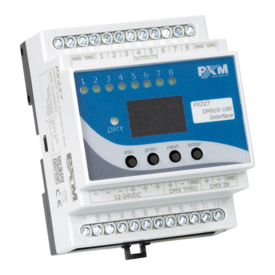
- Page 1 PX227 DMX/0-10V Interface 8ch User manual...
-
Page 2: Table Of Contents
12 Menu scheme..................15 13 Connection scheme................16 14 Dimensions.....................17 15 Technical data..................17 Manufacturer reserves the right to make modifications in order to improve device operation. PXM Marek Żupnik sp.k. Podłęże 654 tel. +48 12 385 83 06 32-003 Podłęże mail: info@pxm.pl Rev.1-5 BDO register number 000005972 www.pxm.pl... -
Page 3: Description
Safety conditions PX227 is a device powered by low voltage equal to 12 – 24V DC; however, please observe the following safety rules during its installation and use: 1. The device mat be connected to 12 – 24V DC with current-carrying capacity compatible with technical data. - Page 4 5. All repairs and connection of outputs or DMX signal can only be made with cut off power supply. 6. PX227 should be strictly protected against contact with water and other liquids. 7. All sudden shocks, particularly dropping, should be avoided.
-
Page 5: Connectors And Control Elements
Connectors and control elements Pin no. Connection GND (-) GND (-) GND (-) GND (-) OUT 1 (+) OUT 2 (+) OUT 3 (+) OUT 4 (+) OUT 5 (+) OUT 6 (+) OUT 7 (+) OUT 8 (+) DC + power type DC + power type DC + power type DC - power type... -
Page 6: Dmx Signal Connection
DMX IN terminals in the device must be provided with the driving cable, and then from DMX OUT connector the driving cable must be provided to other DMX receivers. If PX227 is the last device in DMX line, DMX+ and DMX- resistor of 120 Ohm between pins 22 and Programming After switching on, the display shows the version of the program. -
Page 7: Programming Of Group Parameters
6.1 Setting of DMX address PX227 menu allows to set DMX address of the device in the range from 1 to 505. In order to set DMX address: 1. -
Page 8: Feature Of Output Channels
6.2 Feature of output channels To adjust the feature for all channels set: 1. From the start menu, go to the group settings menu ALL 2. Press enter again in order to change the settings for all channels 3. Use next to select Cur, this will allow to change the characteristic of channel dimming Lin –... -
Page 9: Programming Of Individual Parameters
Programming of individual parameters PX227 device has the option of individual settings. It allows to assign each of the eight output channel with any DMX address. It is possible after selecting Adr. DMX address can be selected within a range from 1 to 512. -
Page 10: Response To The Loss Of Dmx Signal
Response to the loss of DMX signal This function is used both to protect the system against the disappearance of DMX signal and to gain a specific state on outputs. After it has been activated, in case of a lack of DMX signal, the module will perform the selected function by itself. - Page 11 (completely fluid transition). It is possible to reduce the number of program steps, for this purpose, for this purpose, in step which should be last and after this step followed first step, select the on option in the End menu. In each of the four scenes, you can program the values of each of the eight output channels separately in the range from 0 to 255.
-
Page 12: Smoothing Function
Smoothing function The device also has the smoothing option. Smoothing allows for smooth color changes. When this option is enabled, switching between successive DMX values sent to channels is smooth, which prevents abrupt changes in voltage. In order to start the smoothing function, enter the Sth option: 1. -
Page 13: Screen Blanking
Time smoothing tiN allows to set the time of linear transitions between successive DMX values. The minimum value is 10 [ms], and the maximum is 999 [ms]. This can be smoothly changed by selecting the expected value using prev and next buttons. 10 Screen blanking The device has been equipped with the option of switching off backlight of the screen. -
Page 14: Mounting
Installation on the mounting rail: 1. Set PX227 diagonally to the rail by hooking the two supports on the rear panel of the unit on the upper part of the assembly strip. 2. Pull the latch down using a screwdriver. -
Page 15: Menu Scheme
12 Menu scheme ENTER ENTER ENTER NEXT NEXT NEXT ENTER NEXT ENTER ENTER ENTER NEXT NEXT NEXT NEXT ENTER NEXT ENTER ENTER ENTER NEXT ENTER NEXT NEXT NEXT NEXT NEXT NEXT NEXT NEXT ENTER NEXT NEXT NEXT NEXT NEXT NEXT ENTER NEXT NEXT... -
Page 16: Connection Scheme
13 Connection scheme to next fluorescent lamp to next fluorescent lamp Fluorescent lamp controller DC 1-10V e.g. PX333 Electronic Ballast AC 230V Fluorescent lamp DC 1-10V Electronic Ballast AC 230V Electronic ballast terminator powered from 1 - 10 V 230 V AC 50 Hz 12-24V DC Electronic ballast... -
Page 17: Dimensions
14 Dimensions 70 mm 60 mm 12-24V DC 15 Technical data type PX227 power supply 12 – 24V DC number of DMX channels number of output channels voltage on outputs 0 – 10V (±3%) output sockets screw terminals current consumption max. - Page 18 Podłęże, 07.06.2019 DECLARATION OF CONFORMITY PXM Marek Żupnik spółka komandytowa Podłęże 654, 32-003 Podłęże we declare that our product: Product name: DMX/0-10V Interface 8ch Product code: PX227 meets the requirements of the following standards, as well as harmonised standards: PN-EN IEC 63000:2019-01...
Need help?
Do you have a question about the PX227 and is the answer not in the manual?
Questions and answers