Table of Contents
Advertisement
Quick Links
Advertisement
Table of Contents

Subscribe to Our Youtube Channel
Related Manuals for PXM PX218


Summary of Contents for PXM PX218
- Page 1 PX218 Controller MANUAL...
-
Page 2: Table Of Contents
Declaration of conformity................The manufacturer reserves the right to change the operation and handling of the device in order to improve the product. PXM Marek Żupnik spółka komandytowa tel.: (12) 626 46 92 fax: (12) 626 46 94 Podłęże 654 E-mail: info@pxm.pl... -
Page 3: General Description
1. GENERAL DESCRIPTION PX218 - RDM Controller is a multifunction device which allows for changing parameter settings of products connected to complex installations using the DMX-512 protocol. PX218 communicates with other products through the RDM (Remote Device Management) protocol which is a kind of extended DMX512 protocol. The DMX protocol has been designed to enable one-direction flow of data, while its extension, the RDM protocol, can send information in two directions. -
Page 4: Description
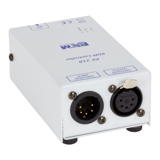
DMX input connector (3-pin XLR female slot) DMX output connector (3-pin XLR female slot) Information diodes: Power: power connection - orange diode Tx: transferring data through PX218 - blue diode Rx: receiving data through PX218 - green diode miniUSB interface (miniUSB type B) -
Page 5: Software Installation
USB driver. The [Device driver installation wizard] will be displayed in another window, click [Next] to continue. 7. The wizard displays the message "The drivers are successfully installed on this computer", click [Finish]. 8. The PX218 installer has successfully installed the software, click [Close]. 9. Open the installed PX218 program. -
Page 6: Controller Software
In such case, indicate the location of the controller displayed at the end of the software installation Px218_PXM_RDM_Controller_P_1_6.exe. The connection is established after selecting the available PX218 from the drop down menu [Devices] in the top left corner of the window. Then, the program displays the “Connected” status, catalogue number of the device,... -
Page 7: Searching For Connected Devices
5.1.1. Searching for connected devices Once the program "PXM RDM Controller” is connected with PX218, it is possible to start searching for all devices connected to the DMX line. To do this, select [Full Discovery] located in the top left corner of the window. After searching and receiving the response from devices connected to the DMX line, the program displays the products found on the right in the [Devices] frame. -
Page 8: General Overview
5.2. General overview The first tab [Device Overview], available for each device found, contains information on the detected product. The displayed messages are divided into sections: [Description], [DMX 512], and [Supported Parameters]. [Description] contains the following information: RDM Protocol Version ź... -
Page 9: Dmx Patch Grid
Additionally, the [Identify] box located under the [Save changes] button allows for activating the option of physical indication of the device among other devices connected to the system (in the case of PXM lamps, this will include blinking of diodes indicating the identified product). 5.2.1. DMX patch grid The [DMX Patch Grid] tab allows for viewing the DMX channels currently assigned to devices connected to the DMX-512 line and with built-in option to support the RDM protocol. - Page 10 DMX values. This function is used only to configure scenes from PC. Once this button is selected, PXM RDM Controller opens another window and displays the [Grid] tab by default. This allows you to set the DMX value.
-
Page 11: Sensors
The [Sliders] tab allows you to change the values of the pre-selected devices or slave devices visible in the menu in the bottom right-hand corner of the main program window. 5.2.2. Sensors The next tab – [Sensors] – is used to check parameters of sensors installed in the device. These may be, for example, temperature sensors. -
Page 12: Rdm Settings
5.2.3. RDM settings The last tab [RDM settings] contains information on all of the RDM parameters provided by the RDM protocol to the device. In addition to viewing the messages, it is also possible to set new values for the options which allow for such a change. Available parameters are displayed on the right-hand side of the window [PID - GET/SET]. -
Page 13: Modification Of Device Times
5.3. Modification of device times The [Timeout] menu in the top left corner of the main program window makes it possible to change the communication settings through various interfaces supported by PX218, i.e. [RDM timeout], [USB timeout], [DMX timeout]. Apart from manual modification of settings, it is also possible to change them automatically. -
Page 14: Wiring Diagram
6. WIRING DIAGRAM Lamp supporting the RDM protocol, e.g. PX256 Connection of the DMX cable from the lamp with the XLR connector The drawing below presents the description of XLR pins: PUSH SHIELD DMX+ DMX- NOTE: Under no circumstances can the cable shield be connected to the device grounding. Example of connecting the DMX cable from the lamp to the cable with XLR connector 1 - black wire - shield 2 - white wire - DMX -... -
Page 15: Technical Specification
7. TECHNICAL SPECIFICATION - available connectors: USB, 3-pin XLR slot/plug - communication with PC: YES (USB Mini-B interface) - power supply: 5V DC (directly from the USB port) - weight: 0,25 kg - dimensions: - length 108 mm - width 61 mm - height 41 mm... -
Page 16: Declaration Of Conformity
30-701 Kraków fax: 12 626 46 94 DECLARATION OF CONFORMITY according to guide line 2004/108/WE Name of producer: PXM Marek Żupnik sp. k. Manufacturer’s address: ul. Przemysłowa 12 30-701 Kraków We declare that our product: Product name: RDM Controller...
Need help?
Do you have a question about the PX218 and is the answer not in the manual?
Questions and answers