Table of Contents
Advertisement
Quick Links
Advertisement
Table of Contents

Subscribe to Our Youtube Channel
Related Manuals for PXM PX781


Summary of Contents for PXM PX781
- Page 1 PX781 Driver LED C.C. 3 x 700mA User manual...
-
Page 2: Table Of Contents
Table of Contents 1 Description....................4 2 Safety conditions..................5 3 Connectors and control elements............6 4 Designation of displayed messages............6 5 Device programming.................8 5.1 Button features......................8 5.2 Group DMX address settings..................9 5.3 Individual DMX address settings................9 5.4 Color settings mode....................10 5.5 No DMX signal response..................13 5.6 Description of DMX no-signal programs..............14 5.7 Master / Slave function...................16... - Page 3 Manufacturer reserves the right to make modifications in order to improve device operation. PXM Marek Żupnik sp.k. Podłęże 654 tel. +48 12 385 83 06 32-003 Podłęże mail: info@pxm.pl Rev.1-0 BDO register number 000005972 www.pxm.pl 21.10.2019...
-
Page 4: Description
LEDs. PX781 can be controlled by the DMX signal or it can work independently. In this operation mode, the user has access to a fully programmable stage and 18 default sequences for which can be also change the reproduction speed and the smoothness of transition of particular steps. -
Page 5: Safety Conditions
Safety conditions PX781 is a device powered with safe voltage 12 – 48V DC; however, during its installation and use the following rules must be strictly observed: 1. The device may only be connected to 12 – 48V DC with current- carrying capacity compatible with technical data. -
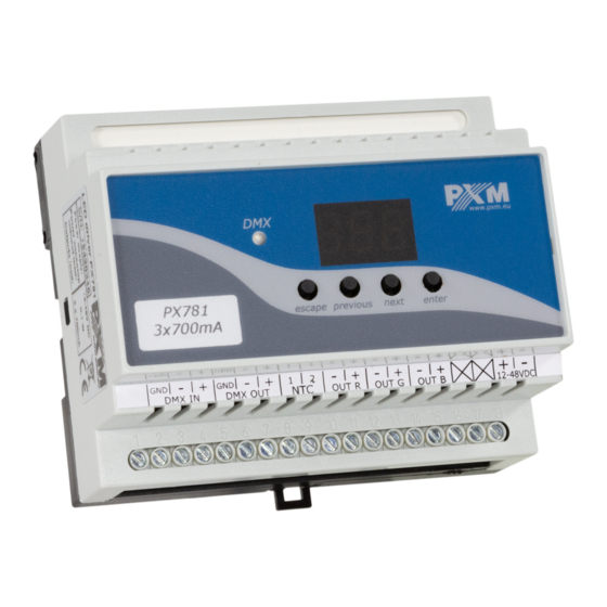
Page 6: Connectors And Control Elements
Connectors and control elements display programming keys PX781 3x700mA control outputs DMX input power supply 12 - 48V DC DMX output NTC 4K7 temperature sensor Designation of displayed messages DMX address of a device – a basic item in the MENU... - Page 7 no DMX signal response method selection Master / Slave mode settings Lightness / Color control mode RGB control mode RGB Dimmer control mode HSL control mode – Hue / Saturation / Lightness effect control mode dynamic white mode all outputs at 100% all outputs off scene program no.
-
Page 8: Device Programming
screen blanking memory error message restore default device settings menu function to limit power value of the limit activation temperature value of the maximum limit temperature current temperature the highest temperature recorded by the sensor the lowest temperature recorded by the sensor temperature limit is switched off and it is not possible to read the following temperatures: maximum, minimum, and current or when a mode which does not use all channels is set, and unused channels... -
Page 9: Group Dmx Address Settings
5.2 Group DMX address settings The menu of the PX781 driver allows for setting the DMX address within a range between 1 and 506 – 511 depending on work mode of device. For example in RGB mode it occupies three consecutive DMX addresses. -
Page 10: Color Settings Mode
ENTER ENTER NEXT ENTER NEXT The PX781 driver can operate in different control modes. Depending on the selected mode, the devices takes up a different NEXT numbers of channels, possible modes: The HSL mode (Hue, Saturation, Lightness) operates on three... - Page 11 Description guide of EFF mode settings (table is on the next page): Channel 1 – red color Channel 2 – green color Channel 3 – blue color Channel 4 – operating mode selection Channel 5 – speed settings (higher value – quicker changes) Channel 6 –...
- Page 12 CHANNEL CHANNEL CHANNEL CHANNEL CHANNEL CHANNEL CHANNEL 8 1 RED 2 GREEN 3 BLUE 5 MODE 6 SPEED 7 FADE BRIGHTNESS <0–7> Program 1 <8–15> Program 2 <16–23> Program 3 <24–31> Program 4 <32–39> Program 5 <40–47> Program 6 <48–55> Program 7 <56–63>...
-
Page 13: No Dmx Signal Response
5.5 No DMX signal response This function is used both to protect the installation against the DMX signal loss and to obtain control over LEDs without connecting an external controller. Once it is activated, if there is no DMX signal the module will realize a desired function independently. -
Page 14: Description Of Dmx No-Signal Programs
Sc –self-programmed scene in which it possible to set values for RGB colors (rEd, Grn, bLu) in range 0 – 255 for each color separately. Additionally can set the scene entry time (SPd) after decay DMX signal in range 0,1 – 99,9s. on –... - Page 15 Step 1 Step 2 Step 3 Step 4 Step 5 Step 6...
-
Page 16: Master / Slave Function
Step 4 5.7 Master / Slave function The PX781 module has a built-in DMX-512 receiver and can be controlled from any desktop or controller running in this standard. Moreover, it is equipped with a programmable function of response to no DMX signal (noS). -
Page 17: White Balance
Sometimes, there can be problems with getting white color on the RGB series LEDs. This may be a result of using diodes with different technical parameters. For this reason, the PX781 module is equipped with a white balance function. This option allows for choosing a correct color temperature... -
Page 18: Smooth
ENTER ENTER ENTER ENTER 4 x NEXT 4 x NEXT ENTER ENTER NEXT NEXT NEXT NEXT bLr – value for the red color (0 – 100) bLr – value for the red colour (0 – 100) bLG – value for the green color (0 – 100) bLG –... -
Page 19: Light Control Frequency
ENTER ENTER ENTER ENTER 5 x NEXT 5 x NEXT ENTER ENTER NEXT NEXT NEXT NEXT PREV PREV ENTER ENTER NEXT NEXT 5.10 Light control frequency The Frq function allows for setting the basic control frequency for the LEDs. This function is extremely useful in applications for the television industry. -
Page 20: Screen Saving (Screen Blanking)
NEXT 5.12 Temperatures limits and sensor failure PX781 has been equipped with a function that limits the output power depending on the temperature value read using the external sensor mounted in the lamp. This allows for programming a temperature value which, if reached, limits the power or disables the lamp supplied by the driver. - Page 21 ENTER The meaning of the statement: tMP – power limitation 4 x NEXT ENTER ENTER management depending on NEXT NEXT temperature read on the external sensor NEXT LiM – powering On and OFF of the power limitation function NEXT Lo – limit activation temperature NEXT value can be set between 30°C and 60°C...
-
Page 22: Display Function
That is why the PX781 driver has a display flip feature available. It turns the screen 180°. The keys order is reversed as well. - Page 23 3s. To deactivate function the procedure is the same. The figure shows how flip function works. standard position PX781 3x700mA upside-down position NOTE! The keys on the reverse of the display are set in the same way as the...
-
Page 24: Default Settings And Device Errors
In such a case, try to restore the device to its default settings before sending the PX781 to the service center. If, after restoring to its default settings, the device still does not operate correctly, please send it to our service center. -
Page 25: Error Message
Error message The device is equipped with a built-in memory work control function. If there are problems with the memory operation on the PX781 display, the Err message appears – memory error. In this situation, select the “enter” key. The device will reload the default configuration and upload it to the memory. -
Page 26: Dmx Signal Connecting
PX781 have to be connected to DMX line in serial mode, with no branches on DMX control cable. That means that DMX line, from the signal source, must be connected to DMX IN pins of PX781 and later, directly from DMX OUT pins to the next device in DMX chain. - Page 27 List of RDM parameters supported by the PX781: Parameter name Description SUPPORTED_PARAMETERS 0x0050 all supported parameters description of additional PARAMETER_DESCRIPTION 0x0051 parameters DEVICE_INFO 0x0060 information concerning the device SOFTWARE_VERSION_LABEL 0x00C0 firmware version of the device DMX starting address of the...
- Page 28 No DMX 0x801C OFF_21 * signal settings of red channel value SCENE_RED * 0x801D for scene saved in PX781 settings of green channel value SCENE_GREEN * 0x801E for scene saved in PX781 settings of blue channel value SCENE_BLUE *...
- Page 29 Parameter name Description programs playback speed settings PROGRAM_SPEED * 0x8025 (playing next steps of program) settings of smooth transition PROGRAM_FADE * 0x8026 between following steps of a program to activate or deactivate the BALANCE ON/OFF * 0x8027 balance of output channels PWM_FREQENCY * 0x8028 LEDs refresh frequency SERIAL_NUMBER *...
-
Page 30: Programming
Programming ENTER ENTER ENTER NEXT NEXT ENTER NEXT NEXT ENTER ENTER NEXT NEXT NEXT NEXT NEXT NEXT ENTER NEXT NEXT NEXT ENTER NEXT NEXT NEXT NEXT ENTER ENTER NEXT NEXT Next page... - Page 31 Previous page ENTER NEXT NEXT ENTER NEXT NEXT ENTER NEXT NEXT NEXT NEXT ENTER NEXT NEXT ENTER NEXT NEXT ENTER ENTER NEXT NEXT NEXT NEXT NEXT NEXT...
-
Page 32: Connection Scheme
BLUE + RED + lampa LED lampa LED lampa LED Example connection the PX781 driver to the LED RGB lamp: the cables should be connected with the correct order of colors • LEDs should be connected only in series •... - Page 33 Connection diagram of the RGB lamp with a built-in temperature sensor (NT C 4K7 thermistor) PX781 3x700mA RGB lamp with built-in NTC 4K7 thermistor The connection of the NTC 4K7 thermistor is applicable only when one lamp is connected to the driver. This is due to the fact that the device can read the temperature from only one lamp.
- Page 34 Monochrome lamp in DW mode connection diagram PX781 3x700mA BLUE + BLUE – mono GREEN + GREEN – warm white RED + RED – cold white...
-
Page 35: Dimensions
10 Dimensions... -
Page 36: Technical Data
11 Technical data type PX781 DMX input 1 (512 channels) DMX output 1 (24 – 512 channels) number of current outputs max current consumption 2.1A no-load power consumption 0.5W output load capacity 700mA / channel (+2% ÷ -5%) output sockets... - Page 37 Podłęże, 21.10.2019 DECLARATION OF CONFORMITY PXM Marek Żupnik spółka komandytowa Podłęże 654, 32-003 Podłęże we declare that our product: Product name: Driver LED C.C. 3 x 700mA Product code: PX781 meets the requirements of the following standards, as well as harmonised...
Need help?
Do you have a question about the PX781 and is the answer not in the manual?
Questions and answers