Table of Contents
Advertisement
Quick Links
Advertisement
Table of Contents

Related Manuals for PXM RDM Controller


Summary of Contents for PXM RDM Controller
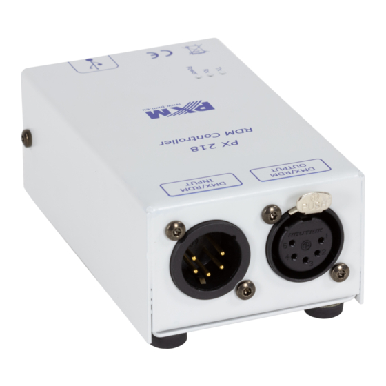
- Page 1 PX218 RDM Controller User manual...
-
Page 2: Table Of Contents
5.4.2 Send DMX......................14 6 Connection scheme.................15 7 Dimensions....................16 8 Technical data..................16 Manufacturer reserves the right to make modifications in order to improve device operation. PXM Marek Żupnik sp.k. Podłęże 654 tel. +48 12 385 83 06 Soft. 2.1.X 32-003 Podłęże mail: info@pxm.pl Rev.1-2... -
Page 3: Description
PX218 operation management is carried out using the program via a USB port. The application is available for download from the manufacturer’s website (pxm.pl). To power the device, all you need is power supplied from a USB porn on your computer. -
Page 4: Safety Conditions
Safety conditions PX218 RDM Controller is a device powered directly from the USB port with safe voltage 5V DC, however, during its installation and use the following rules must be strictly observed: 1. The device can only be connected to the power supply directly from the USB port. -
Page 5: Connectors And Control Elements
Connectors and control elements Designations: 1. DMX input connector (3-pin or 5-pin XLR male slot) 2. DMX output connector (3-pin or 5-pin XLR female slot) 3. Information diodes: ◦ Power: power connection – orange diode ◦ Tx: transferring data through PX218 – blue diode ◦... -
Page 6: Software Installation
Run option. The installation file is attached to the device on a CD or available for download from the manufacturer’s website (pxm.pl). 2. The PX218 Installation Wizard will start, go to Next. 3. Select the directory where the software will be installed. Confirm your choice by clicking the Next button. -
Page 7: Controller Software
9. After the installation is completed, the wizard will display a window informing about the installation completion. Click Finish to complete the installer. Controller software Program designed to manage the PX218 controller via a PC allows to easily program devices supported by the RDM (Remote Device Management) protocol. -
Page 8: Searching For Connected Devices
5.1.1 Searching for connected devices After connecting the RDM Controller to the DMX line, you can start searching for devices. To do this, select the RDM application in the upper left corner where the following options are available: Add discovery – searches for devices bypassing any devices •... - Page 9 On the left side of the program all devices that communicate with PX218 are displayed. In order to obtain information and changes the parameters of the device searched by RDM Controller, select it from the list, all information that has been read will be displayed on the right side of the window.
-
Page 10: Rdm
5.2 RDM The first tab (RDM) displays basic information about the detected product. In addition to basic information, additional, expandable sections are available: Statistic, Sensors and Advanced RDM parameters. The RDM section has the following options: Basic information • ◦ Device model ◦... - Page 11 ◦ Footprint – number of channels occupied by the device ◦ Start address – editable option to set the device’s start address Statistic – displays information on e.g. operation time, lamp usage • time, etc. Sensors – shows sensor readings e.g. CPU, NTC temperature, etc. In •...
-
Page 12: Address
5.3 Address The Address tab allows to view the currently occupied DMX channels by devices connected to the line that have RDM support. The channels occupied by the entire device are marked green, the yellow devices are marked with subdevices. Orange with the symbol “*”... -
Page 13: Dmx Out
5.4 DMX OUT The last DMX OUT tab contains information about DMX parameters and the sent DMX signal to devices on the DMX line. 5.4.1 DMX parameters The following DMX parameters are in the upper part of the window : Send DMX –... -
Page 14: Send Dmx
5.4.2 Send DMX The program allows sending DMX signal in real time with a set value on individual channels, unfortunately there is no option to save the set DMX values. This function is only used to view the behavior of devices when receiving a specific value on a specific DMX channel. -
Page 15: Connection Scheme
Connection scheme Lamp supporting the RDM protocol, e.g. PX329... -
Page 16: Dimensions
Dimensions Technical data type PX218 power supply 5V DC (directly from the USB port) available connectors USB, 3-pin or 5-pin XLR slot / plug communication with PC yes (USB USB Mini-B interface) weight 0.25kg width: 61mm dimensions height: 108mm depth: 41mm... - Page 17 Podłęże, 16.09.2019 DECLARATION OF CONFORMITY PXM Marek Żupnik spółka komandytowa Podłęże 654, 32-003 Podłęże we declare that our product: Product name: RDM Controller Product code: PX218 meets the requirements of the following standards, as well as harmonised standards: PN-EN IEC 63000:2019-01...
Need help?
Do you have a question about the RDM Controller and is the answer not in the manual?
Questions and answers