Table of Contents
Advertisement
Advertisement
Table of Contents

Related Manuals for Marcy BK1016US


Summary of Contents for Marcy BK1016US
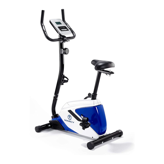
- Page 1 BK1016US UPRIGHT BIKE USER MANUAL...
-
Page 2: Table Of Contents
CONTENTS Important Safety Information Weight Limit Capacities Hardware Parts List Pre Assembly Check List 6 - 11 Assembly Instructions 12-13 Computer Instructions 14-15 Exercise Instructions 16-17 Exploded Diagram 18-19 Parts List ADDITIONAL INFORMATION Limited Warranty Information Supplied by: Pure-Tec Limited Tel: +44 (0) 1482 212098 Email: service@puretecfitness.com www.puretecfitness.com... -
Page 3: Important Safety Information
IMPORTANT SAFETY INFORMATION READ ALL INSTRUCTIONS BEFORE USING THIS OWNER’S MANUAL CONTAINS ASSEMBLY, OPERATION, MAINTENANCE AND SAFETY INFORMATION. IN THE INTEREST OF SAFETY, PLEASE MAKE CERTAIN THAT YOU READ AND UNDERSTAND ALL THE INFORMATION BELOW. 1. This Bike is intended for class H (H=Domestic) use only. It is not designed for commercial use. -
Page 4: Hardware Parts List
HARDWARE PACKING LIST Description DRAWING Q’ty Carriage Bolt M10*75 Curved Washer Φ22*Φ10 Domed Nut Quick Release Knob Allen Bolt M8*16 Decorative Cover T-type Knob Curved Washer Φ20*Φ8 Box Wrench Allen key L6... -
Page 5: Pre Assembly Check List
PRE-ASSEMBLY CHECK LIST NO.1 NO.22 NO.15 NO.9 NO.10 NO.18 NO.19 NO.3 NO.2 NO.41 NO.16 PART NO. DESCRIPTION Q’TY Main frame Front support Seat support Meter 9/10 Pedal ( L/R ) Seat Handlebar Front stabilizer Rear stabilizer Bottle holder... -
Page 6: Assembly Instructions
ASSEMBLY INSTRUCTION STEP 1 Attach the front stabilizer (03) to the main frame (01), Secure using two carriage bolts (06), two curved washers (07), two domed nuts (08). Attach the rear stabilizer (02) to the main frame (01), Secure using two carriage bolts (06), two curved washers (07), two domed nuts (08). - Page 7 STEP 2 Take front post (22) and connect middle sensor wire (24) with lower sensor wire(23) Adjust the tension control knob(20) to level 8, then connect it with the lower tension cable (21). Insert front post (22) into main frame (1) and tighten with 4 sets of allen bolt (17) and curved washers (42).
- Page 8 HOW TO CONNECT TENSION CONNECTOR Slide the Cable wire from the extension sensor wire Connector in between the opening on the wire holder on sensor wire Connector. Pull the extension sensor wire Connector backward and slide the wire through the slot on the bracket.
- Page 9 STEP 3 Attach handlebar (19) to front post (22), tighten with a clip (25) and allen bolt (25), decorative cover (27) and T type knob (28). Connect upper sensor wire from the back of computer (18) with middle sensor wire (24). Insert the lower pulse wire (43) through grommet (75) on front post (22) and pull the middle sensor wire (43) out of front post (22) Connect lower pulse wire (43) with upper pulse wire from the back of the computer (18).
- Page 10 STEP 4 Attach seat (16) to seat post (15), tighten with knob (34), sleeve (33), washer (32) and bowl shaped nut (31)). Insert seat post (15) into main frame (1), tighten with quick release knob (11). 31 32...
- Page 11 STEP 5 Attach the bottle holder (41) to the front post (22) with two self tapping screws (70). Attach the left and right pedal straps to the left and right pedals (9/10). Attach the left and right pedals (9/10) to the left and right crank arms. Note: The pedals and crank arms are marked with "R"...
-
Page 12: Computer Instructions
COMPUTER INSTRUCTIONS FUNCTIONAL BUTTONS: MODE - Push down for selecting functions. - To Set the consumer movement of time、distance、calories and hand pulse. RESET -For resetting consumer movement of time、distance、calories and hand pulse. FUNCTION AND OPERATIONS: 1. SCAN: Press “MODE” button until “SCAN” appears, monitor will rotate through all the 6 functions: Time、speed、distance、calorie ODO and pulse. - Page 13 NOTE: 1. If the display is faint or shows no figures ,please replace the batteries. 2. The monitor will automatically shut off if there is no signal received after 4 minutes . SPECIFICATIONS: AUTO SCAN Every 6 seconds TIME 00:00’~99:59’ CURRENT The maximum signal can be pickup is SPEED...
-
Page 14: Exercise Instructions
EXERCISE INSTRUCTIONS Using your UPRIGHT BIKE will provide you with several benefits, it will improve your physical fitness, tone muscle and in conjunction with a calorie controlled diet help you lose weight. 1. The Warm Up Phase This stage helps get the blood flowing around the body and the muscles working properly. It will also reduce the risk of cramp and muscle injury. - Page 15 3. The Cool Down Phase This stage is to let your Cardio-vascular System and muscles wind down. This is a repeat of the warm up exercise e.g. reduce your tempo, continue for approximately 5 minutes. The stretching exercises should now be repeated, again remembering not to force or jerk your muscles into the stretch.
-
Page 16: Exploded Diagram
EXPLODED DIAGRAM... -
Page 18: Parts List
PARTS LIST PART NO. DESCRIPTION Q’TY Main Frame Rear Stabilizer Front Stabilizer End Cap For Front Stabilizer End Cap For Rear Stabilizer Carriage Bolt M10*75 Curved Washer Φ10*Φ22 Domed Nut M10 Left Pedal Right Pedal Quick Release Knob Washer Φ17*Φ8 Spring Washer Φ8 Nylon Nut M8 Seat Post... - Page 19 PARTS LIST PART NO. DESCRIPTION Q’TY Screw Bushing Bottle holder Curved Washer Φ8*Φ20 Lower Pulse Wire Axle for Flywheel Bearing Washer Spring Clutch Small pulley Bearing Nut M10*1.25 Bowl Shaped Spacer Allen Bolt M8*105 Crank BB assembly Pulley Flywheel Idler Assembly Belt Magnetic Assembly Spacer...
-
Page 20: Additional Information
ADDITIONAL INFORMATION Packaging Disposal Government guidelines ask that we reduce the amount of waste material disposed of in land fill sites. We therefore ask that you dispose of all packaging waste responsibly at public recycling centres. End of Life Disposal We at Pure-Tec Limited hope you enjoy many years of enjoyable use from your Bike. -
Page 21: Limited Warranty Information
LIMITED WARRANTY Pure-Tec. warrants this product to be free from defects in workmanship and material, under normal use and service conditions. Please refer to www.puretecfitness.com warranty conditions. This warranty extends only to the original purchaser and is valid for home use only. Pure-Tec’s obligation under this Warranty is limited to replacing damaged or faulty parts at Pure-Tec’s option.
Need help?
Do you have a question about the BK1016US and is the answer not in the manual?
Questions and answers
How do I take off the arm that the pedal is screwd into. Pedal is stripped
The document does not provide specific instructions on removing the arm where the pedal is screwed in on the Marcy BK1016US. However, based on standard assembly information:
1. Remove the pedal from the crank arm by unscrewing it (left pedal unscrews clockwise, right pedal counterclockwise).
2. Use a crank puller tool to remove the crank arm from the bike.
Detailed removal steps are not included in the provided content.
This answer is automatically generated
The extension wire is not enough for it to slide into the bracket. The adjuster is at its limit.