Table of Contents
Advertisement
Quick Links
Advertisement
Table of Contents

Related Manuals for Marcy RB1016


Summary of Contents for Marcy RB1016
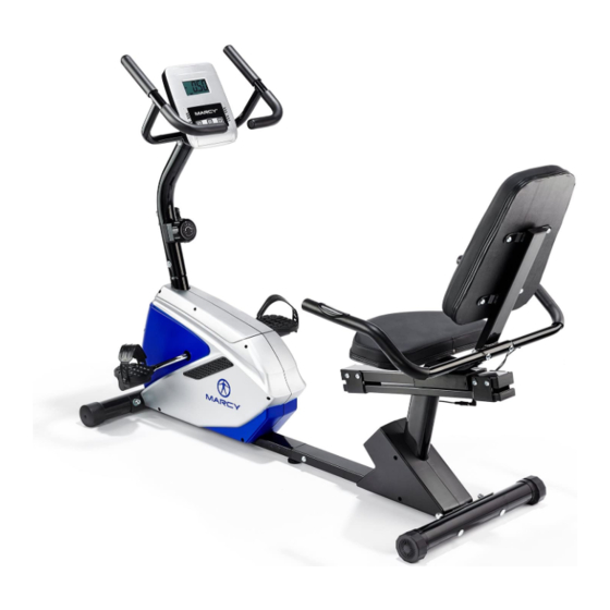
- Page 1 RB1016 RECUMBENT BIKE USER MANUAL...
- Page 2 CONTENTS Important Safety Information Weight Limit Capacities Hardware Parts List Pre Assembly Check List Assembly Instructions 6-11 Computer Instructions 12-13 Exercise Instructions 14-15 Exploded Diagram 16-17 Parts List 18-19 ADDITIONAL INFORMATION Limited Warranty Supplied by: Pure-Tec Limited Tel: +44 (0) 1482 212098 Email: service@puretecfitness.com www.puretecfitness.com...
-
Page 3: Important Safety Information
IMPORTANT SAFETY INFORMATION READ ALL INSTRUCTIONS BEFORE USING THIS OWNER’S MANUAL CONTAINS ASSEMBLY, OPERATION, MAINTENANCE AND SAFETY INFORMATION. IN THE INTEREST OF SAFETY, PLEASE MAKE CERTAIN THAT YOU READ AND UNDERSTAND ALL THE INFORMATION BELOW. 1. This Bike is intended for class H (H=Domestic) use only. It is not designed for commercial use. -
Page 4: Hardware Packing List
HARDWARE PACKING LIST Description Q’ty Identifier Allen screw M8*16 Curved washer Φ8*Φ20 Carriage bolt M10*75 Domed nut M10 Leveling pad Quick release knob Flat washer Φ8*Φ17 Carriage bolt M10*40 Domed nut M8 Curved washerΦ10*Φ22 Crossing wrench Allen keyL6... - Page 5 PRE-ASSEMBLY CHECK LIST PART NO. DESCRIPTION Q’TY Main frame Computer Seat support tube Sliding frame Front Stabilizer Rear Stabilizer Front post Pedal L/R Back Cushion Seat Cushion Handlebar Decorative cover L/R Sliding tube Bottle holder Stationary handlebar L/R...
- Page 6 ASSEMBLY INSTRUCTION STEP 1 Attach the front stabilizer (14) to the main frame (1), securing with two carriage bolts (13), two curved washers (66) and two domed nuts (19). 66 19 STEP 2 Connect middle extension pulse wire (63) with rear extension pulse wire (64). Attach sliding frame (26) to main frame (1), and tighten with six allen screws (8) and flat washers (27).
- Page 7 STEP 3 Connect the upper extension sensor wire (10) to the lower sensor wire (12). Connect the front extension hand pulse wire (60) to the middle extension hand pulse wire (63). Connect the tension control cable (7) to the extension tension cable (11). Attach front post (4) to the main frame (1).
- Page 8 HOW TO CONNECT TENSION CONNECTOR Slide the Cable wire from the extension sensor wire Connector in between the opening on the wire holder on sensor wire Connector. Pull the extension sensor wire Connector backward and slide the wire through the slot on the bracket.
- Page 9 STEP 4 Insert the sliding tube (68) into seat support bracket (25). Line up the holes and secure sliding tube (68) with quick release knob (24). Attach seat cushion (32) to the seat support bracket (25). Secure using four allen screws (8). Attach the sliding tube (68) to the sliding frame (26).
- Page 10 STEP 5 Attach rear handlebar (22) to the seat support bracket (25). Secure using two carriage bolts (31), two curved washers (9) and two domed nuts (33). Connect rear extension hand pulse wire (64) to the hand pulse wire (65). Tip: Avoid pinching the pulse Wires Attach the left stationary handlebar (74L) to the front post (4).
- Page 11 STEP 6 Attach bottle holder (72) to the front post (4). Secure using two self tapping screws (16). Attach decorative cover L/R (71L/R) to the sliding frame (26). Secure using four self tapping screws (16) and one self tapping screw (61). CHECK ALL BOLTS AND NUTS ARE TIGHTENED BEFORE USING THE MACHINE...
-
Page 12: Computer Instructions
COMPUTER INSTRUCTIONS FUNCTIONAL BUTTONS: MODE - Push down for selecting functions. - To Set the consumer movement of time、distance、calories and hand pulse. RESET -For resetting consumer movement of time、distance、calories and hand pulse. FUNCTION AND OPERATIONS: 1. SCAN: Press “MODE” button until “SCAN” appears, monitor will rotate through all the 6 functions: Time、speed、distance、calorie ODO and pulse. - Page 13 NOTE: 1. If the display is faint or shows no figures ,please replace the batteries. 2. The monitor will automatically shut off if there is no signal received after 4 minutes . SPECIFICATIONS: AUTO SCAN Every 6 seconds TIME 00:00’~99:59’ CURRENT The maximum signal can be pickup is SPEED...
- Page 14 EXERCISE INSTRUCTIONS Using your RECUMBENT BIKE will provide you with several benefits, it will improve your physical fitness, tone muscle and in conjunction with a calorie controlled diet help you lose weight. 1. The Warm Up Phase This stage helps get the blood flowing around the body and the muscles working properly. It will also reduce the risk of cramp and muscle injury.
- Page 15 3. The Cool Down Phase This stage is to let your Cardio-vascular System and muscles wind down. This is a repeat of the warm up exercise e.g. reduce your tempo, continue for approximately 5 minutes. The stretching exercises should now be repeated, again remembering not to force or jerk your muscles into the stretch.
-
Page 16: Exploded Diagram
EXPLODED DIAGRAM 66 19 8 70 64 8 8 26 19... -
Page 18: Part List
PART LIST Key No. Description Main frame Computer Philips Screw M5*10 Front Post Flat washer Φ5 Screw M5*40 Tension control knob w/cable Allen screw M8*16 Curved washer Φ8*Φ20 Upper computer sensor wire Lower tension cable Lower computer sensor wire Carriage bolt M10*75 Front stabilizer End cap for front stabilizer Self tapping screw ST5*16... - Page 19 PART LIST Key No. Description BB parts Spacer Allen bolt M8*105 Spacer for magnetic assembly Magnetic assembly Spring for magnetic assembly Hex head screw M6*25 Nut M6 Lower foam grip for stationary handlebar Flange nut Allen screw M8*20 Belt Nut M8 Hex head screw M8*45 Idler assembly Chain cover L/r...
- Page 20 ADDITIONAL INFORMATION Packaging Disposal Government guidelines ask that we reduce the amount of waste material disposed of in land fill sites. We therefore ask that you dispose of all packaging waste responsibly at public recycling centres. End of Life Disposal We at Pure-Tec hope you enjoy many years of enjoyable use from your Bike.
-
Page 21: Limited Warranty
LIMITED WARRANTY Pure-Tec. warrants this product to be free from defects in workmanship and material, under normal use and service conditions. Please refer to www.puretecfitness.com warranty conditions. This warranty extends only to the original purchaser and is valid for home use only. Pure-Tec’s obligation under this Warranty is limited to replacing damaged or faulty parts at Pure-Tec’s option.
Need help?
Do you have a question about the RB1016 and is the answer not in the manual?
Questions and answers
The computer shows P for pulse rate but don't show any numbers when I put my hands on the sensors.
The Marcy RB1016 may show 'P' for pulse rate but no numbers if there is poor contact between your hands and the pulse sensors. It may also occur during the first 2–3 seconds of measurement due to contact jamming. Ensure your palms are properly placed on both contact pads and wait 6–7 seconds for the monitor to display the heart rate.
This answer is automatically generated