
Related Manuals for Eaton Powerware 9390 IAC-B


Summary of Contents for Eaton Powerware 9390 IAC-B
- Page 1 Powerware 9390 Integrated Accessory Cabinet ® IAC-B and IAC-T Configurations Installation and Operation Manual For use with Powerware 9390 40–80 kVA and 100–160 kVA UPS Models...
- Page 2 CE MANUEL CONTIENT DES CONSIGNES DE SÉCURITÉ IMPORTANTES Powerware is a registered trademark of Eaton Electrical Inc. ECopyright 2005-2006 Eaton Corporation, Raleigh, NC, USA. All rights reserved. No part of this document may be reproduced in any way without the express written approval of Eaton Corporation.
-
Page 3: Table Of Contents
......... 3-31 EATON Powerware 9390 IAC-B and IAC-T Installation and Operation Manual S 164201590 Rev C powerware.com... - Page 4 ......5-11 IAC Operation – Parallel Redundant Configuration with Maintenance Bypass ..5-11 EATON Powerware 9390 IAC-B and IAC-T Installation and Operation Manual S 164201590 Rev C powerware.com ®...
- Page 5 ..............EATON Powerware 9390 IAC-B and IAC-T Installation and Operation Manual S 164201590 Rev C powerware.com...
- Page 6 Table of Contents This page intentionally left blank. EATON Powerware 9390 IAC-B and IAC-T Installation and Operation Manual S 164201590 Rev C powerware.com ®...
- Page 7 Figure 5-4. Powerware 9390 IAC MOB 1, MOB 2, MBP, and MIS Controls ..... EATON Powerware 9390 IAC-B and IAC-T Installation and Operation Manual S 164201590 Rev C powerware.com...
- Page 8 This page intentionally left blank. EATON Powerware 9390 IAC-B and IAC-T Installation and Operation Manual S 164201590 Rev C powerware.com ®...
-
Page 9: Introduction
IAC with MOB 1 and MOB 2 IAC with MOB 1, MOB 2, and SLB IAC with MOB 1, MOB 2, MBP, and MIS EATON Powerware 9390 IAC-B and IAC-T Installation and Operation Manual S 164201590 Rev C powerware.com ®... -
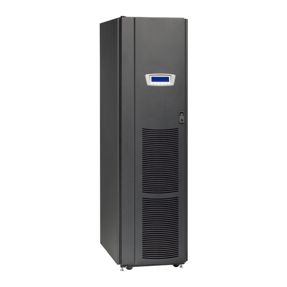
Page 10: Figure 1-1. Powerware 9390 Iac
Introduction Figure 1-1. Powerware 9390 IAC EATON Powerware 9390 IAC-B and IAC-T Installation and Operation Manual S 164201590 Rev C powerware.com ®... -
Page 11: Using This Manual
Appendix A, “Installation Information” – requirements and recommendations, and important diagrams of the cabinets’ mechanical details and electrical access. provides the Eaton warranty for this product. Warranty – Read through each procedure before beginning the procedure. Perform only those procedures that apply to the IAC being installed or operated. -
Page 12: Conventions Used In This Manual
The term standalone refers to cabinets that are not physically attached to the UPS, and are wired with external contractor-supplied wiring. EATON Powerware 9390 IAC-B and IAC-T Installation and Operation Manual S 164201590 Rev C powerware.com... -
Page 13: Safety Warnings
Keep surroundings uncluttered, clean, and free from excess moisture. Observe all DANGER, CAUTION, and WARNING notices affixed to the inside and outside of the equipment. EATON Powerware 9390 IAC-B and IAC-T Installation and Operation Manual S 164201590 Rev C powerware.com ®... -
Page 14: For More Information
Regional locations and telephone numbers A question about any of the information in this manual A question this manual does not answer Please call the Eaton Help Desk for Powerware products at: In the United States 1-800-843-9433 or 1-919-870-3028 In Canada... -
Page 15: Section I - Installation
Section I Installation EATON Powerware 9390 IAC-B and IAC-T Installation and Operation Manual S 164201590 Rev C powerware.com ®... - Page 16 This page intentionally left blank. EATON Powerware 9390 IAC-B and IAC-T Installation and Operation Manual S 164201590 Rev C powerware.com ®...
-
Page 17: Iac Installation Plan And Unpacking
For the IAC to operate at peak efficiency, the installation site should meet the environmental parameters outlined in this manual. If the IAC is to be operated at an altitude higher than 1500m (5000 ft), contact your Eaton service representative for important information about high altitude operation. The operating environment must... -
Page 18: Environmental Considerations
IAC control wiring requirements can be found on Drawing 164201590-7 starting on page A-56 and should be connected at the IAC interface terminal block located inside the IAC. EATON Powerware 9390 IAC-B and IAC-T Installation and Operation Manual S 164201590 Rev C powerware.com ®... -
Page 19: Inspecting And Unpacking The Iac
The IAC is heavy (see Table A on page A-6). If unpacking instructions are not closely followed, the cabinet may tip and cause serious injury. Do not install a damaged cabinet. Report any damage to the carrier and contact your Eaton service representative immediately. - Page 20 6. Inspect the contents for any evidence of physical damage, and compare each item with the Bill of Lading. If damage has occurred or shortages are evident, contact your Eaton service representative immediately to determine the extent of the damage and its impact upon further installation.
-
Page 21: Installing The Iac
C A U T I O N ° Do not tilt cabinets more than 10 from vertical. EATON Powerware 9390 IAC-B and IAC-T Installation and Operation Manual S 164201590 Rev C powerware.com ®... - Page 22 10. Discard or recycle the pallet and unused shipping brackets in a responsible manner. 11. Roll the cabinet to its final installation location. 12. Proceed to paragraph 3.3. EATON Powerware 9390 IAC-B and IAC-T Installation and Operation Manual S 164201590 Rev C powerware.com ®...
-
Page 23: Figure 3-1. Removing The Front Shipping Bracket On The Powerware 9390 Iac
SHIPPING BRACKET PALLET BOLTS FRONT SHIPPING BRACKET SHIPPING BRACKET BOLTS FRONT VIEW Figure 3-1. Removing the Front Shipping Bracket on the Powerware 9390 IAC EATON Powerware 9390 IAC-B and IAC-T Installation and Operation Manual S 164201590 Rev C powerware.com ®... -
Page 24: Figure 3-2. Removing The Rear Shipping Bracket On The Powerware 9390 Iac
SHIPPING BRACKET PALLET BOLTS REAR SHIPPING BRACKET SHIPPING BRACKET BOLTS REAR VIEW Figure 3-2. Removing the Rear Shipping Bracket on the Powerware 9390 IAC EATON Powerware 9390 IAC-B and IAC-T Installation and Operation Manual S 164201590 Rev C powerware.com ®... -
Page 25: Iac Cabinet Installation - Maintenance Bypass Configuration
Powerware 9390 Installation and Operation manual, listed in paragraph 1.5, for installation instructions. 2. Roll the IAC to an area near the right-hand side of the UPS. EATON Powerware 9390 IAC-B and IAC-T Installation and Operation Manual S 164201590 Rev C powerware.com ®... -
Page 26: Figure 3-4. 100-160 Kva Ups With Line-Up-And-Match Iac
10. Remove the knockouts on the bottom left side of the IAC inside panel (see Drawing 164201590-5, sheet 2 of 2 on page A-33). EATON Powerware 9390 IAC-B and IAC-T Installation and Operation Manual S 164201590 Rev C powerware.com ®... - Page 27 UPS using the M4 screw, and to the hinge on the IAC using the screw removed in Step 22 (see Figure 3-5). EATON Powerware 9390 IAC-B and IAC-T Installation and Operation Manual S 164201590 Rev C powerware.com...
-
Page 28: Figure 3-5. 40-80 Kva Ups To Iac Joining Brackets
28. Remove the right-hand screw from the top right-hand door hinge of the UPS cabinet and the left-hand screw from the top left door hinge of the IAC. EATON Powerware 9390 IAC-B and IAC-T Installation and Operation Manual S 164201590 Rev C powerware.com... -
Page 29: Figure 3-6. 100-160 Kva Ups To Iac Joining Brackets
Bracket from Kit Existing Hinge Existing Hinge Nuts from Kit Front View with Large Bracket Figure 3-6. 100–160 kVA UPS to IAC Joining Brackets EATON Powerware 9390 IAC-B and IAC-T Installation and Operation Manual S 164201590 Rev C powerware.com ®... -
Page 30: Installing Iac Line-Up-And-Match Mbp Power Wiring
IAC MBP bypass terminals. 9. If wiring an IAC with a BIB, or BIB and RIB, proceed to Step 10; otherwise, proceed to Step 19. 3-10 EATON Powerware 9390 IAC-B and IAC-T Installation and Operation Manual S 164201590 Rev C powerware.com ®... - Page 31 20. Connect phase A, B, and C, and, if required, Neutral power wiring from the IAC MIS output terminals to the critical load. 3-11 EATON Powerware 9390 IAC-B and IAC-T Installation and Operation Manual S 164201590 Rev C powerware.com ®...
-
Page 32: Standalone Mbp Iac Installation
2. Roll the IAC to the installation area. 3. If not already open, unfasten the IAC front door latch and swing the door open. 3-12 EATON Powerware 9390 IAC-B and IAC-T Installation and Operation Manual S 164201590 Rev C powerware.com ®... -
Page 33: Figure 3-8. 100-160 Kva Ups With Standalone Iac
3-3 and Figure 3-2 on page 3-4). 10. Secure the cabinet to the floor with contractor-supplied hardware. 11. Proceed to paragraph 3.3.4. 3-13 EATON Powerware 9390 IAC-B and IAC-T Installation and Operation Manual S 164201590 Rev C powerware.com ®... -
Page 34: Installing Iac Standalone Mbp Power Wiring
IAC MBP bypass input terminals. 9. If wiring an IAC with a BIB, or BIB and RIB, proceed to Step 10; otherwise, proceed to Step 19. 3-14 EATON Powerware 9390 IAC-B and IAC-T Installation and Operation Manual S 164201590 Rev C powerware.com ®... - Page 35 21. After wiring the UPS system to the facility power and critical load, be sure to ground the system according to local and/or national electrical wiring codes. 3-15 EATON Powerware 9390 IAC-B and IAC-T Installation and Operation Manual S 164201590 Rev C powerware.com ®...
-
Page 36: Installing Iac Mbp Tb1 Interface Connections
8. Reinstall the door removed in previous steps and secure with the retained hardware. 9. Close the door and secure the latch. 3-16 EATON Powerware 9390 IAC-B and IAC-T Installation and Operation Manual S 164201590 Rev C powerware.com ®... -
Page 37: Iac Cabinet Installation - 1+1 Parallel Redundant Configuration
2. Prepare UPM 2 for installation according to the the procedures in the applicable Powerware 9390 Installation and Operation manual, listed in paragraph 1.5. 3-17 EATON Powerware 9390 IAC-B and IAC-T Installation and Operation Manual S 164201590 Rev C powerware.com ®... -
Page 38: Figure 3-10. Two 100-160 Kva Upms With Line-Up-And-Match Iac
10. If necessary, remove the cosmetic covers and hanger brackets from the left-hand and right-hand side of the IAC. Save the covers, screws, and brackets for later use. 3-18 EATON Powerware 9390 IAC-B and IAC-T Installation and Operation Manual S 164201590 Rev C powerware.com ®... - Page 39 100–160 kVA UPS with an IAC, proceed to Step 36. 25. Remove the left-hand screw from the top door hinge on the IAC. 3-19 EATON Powerware 9390 IAC-B and IAC-T Installation and Operation Manual S 164201590 Rev C powerware.com ®...
-
Page 40: Figure 3-11. 40-80 Kva Upm 1 To Iac Joining Brackets
M4 Screws Nut from Kit from Kit Front View with Large Angle Bracket Figure 3-11. 40–80 kVA UPM 1 to IAC Joining Brackets 3-20 EATON Powerware 9390 IAC-B and IAC-T Installation and Operation Manual S 164201590 Rev C powerware.com ®... -
Page 41: Figure 3-12. Iac To 40-80 Kva Upm 2 Joining Brackets
M4 Screws Nut from Kit from Kit Front View with Large Angle Bracket Figure 3-12. IAC to 40–80 kVA UPM 2 Joining Brackets 3-21 EATON Powerware 9390 IAC-B and IAC-T Installation and Operation Manual S 164201590 Rev C powerware.com ®... -
Page 42: Figure 3-13. 100-160 Kva Upm 1 To Iac Joining Brackets
UPM 1 Existing Hinge Existing Hinge Nuts from Kit Front View with Large Bracket Figure 3-13. 100–160 kVA UPM 1 to IAC Joining Brackets 3-22 EATON Powerware 9390 IAC-B and IAC-T Installation and Operation Manual S 164201590 Rev C powerware.com ®... -
Page 43: Figure 3-14. Iac To 100-160 Kva Upm 2 Joining Brackets
M4 Screws Nut from Kit from Kit Front View with Large Angle Bracket Figure 3-14. IAC to 100–160 kVA UPM 2 Joining Brackets 3-23 EATON Powerware 9390 IAC-B and IAC-T Installation and Operation Manual S 164201590 Rev C powerware.com ®... -
Page 44: Installing Iac Line-Up-And-Match Parallel Power Wiring
1.5, for UPS cabinet terminal locations and termination requirements. 8. Connect phase A, B, and C, and, if required, Neutral power wiring from MOB 2 to UPM 2. 3-24 EATON Powerware 9390 IAC-B and IAC-T Installation and Operation Manual S 164201590 Rev C powerware.com ®... - Page 45 24. Reinstall the door removed in previous steps and secure with the retained hardware. 25. Close the door and secure the latch. 3-25 EATON Powerware 9390 IAC-B and IAC-T Installation and Operation Manual S 164201590 Rev C powerware.com ®...
-
Page 46: Standalone Parallel Iac Installation
5. Remove the screws securing the internal safety shield panels, and remove the panels to gain access to the inside of the cabinet. 3-26 EATON Powerware 9390 IAC-B and IAC-T Installation and Operation Manual S 164201590 Rev C powerware.com ®... -
Page 47: Figure 3-16. Two 100-160 Kva Upms With Standalone Iac
3-3 and Figure 3-2 on page 3-4). 10. Secure the cabinet to the floor with contractor-supplied hardware. 11. Proceed to paragraph 3.4.4. 3-27 EATON Powerware 9390 IAC-B and IAC-T Installation and Operation Manual S 164201590 Rev C powerware.com ®... -
Page 48: Installing Iac Standalone Parallel Power Wiring
10. Route the output cables from the critical load to the IAC SLB output terminals. See Drawing 164201590-6, starting on page A-34, for IAC wiring access information and terminal locations. 3-28 EATON Powerware 9390 IAC-B and IAC-T Installation and Operation Manual S 164201590 Rev C powerware.com ®... - Page 49 24. Reinstall the door removed in previous steps and secure with the retained hardware. 25. Close the door and secure the latch. 3-29 EATON Powerware 9390 IAC-B and IAC-T Installation and Operation Manual S 164201590 Rev C powerware.com ®...
-
Page 50: Installing Iac Mbp And Mob Tb1 Interface Connections
9. Reinstall the door removed in previous steps and secure with the retained hardware. 10. Close the door and secure the latch. 3-30 EATON Powerware 9390 IAC-B and IAC-T Installation and Operation Manual S 164201590 Rev C powerware.com ®... -
Page 51: Initial Startup
Installing the IAC 3.5 Initial Startup Startup and operational checks must be performed by an authorized Eaton Customer Service Engineer, or the warranty terms specified on page W-1 become void. This service is offered as part of the sales contract for the UPS system. Contact service in advance (usually a two-week notice is required) to reserve a preferred startup date. - Page 52 - A 120 Vac service outlet is located within 25 feet of the UPS and IAC equipment. - The debris shield covering the IAC cabinet ventilation grill is removed. - Startup and operational checks are performed by an authorized Eaton Customer Service Engineer. 3-32 EATON Powerware 9390 IAC-B and IAC-T Installation and Operation Manual S 164201590 Rev C powerware.com...
- Page 53 Installing the IAC Notes _________________________________________________________________________ _________________________________________________________________________ _________________________________________________________________________ _________________________________________________________________________ _________________________________________________________________________ _________________________________________________________________________ _________________________________________________________________________ _________________________________________________________________________ _________________________________________________________________________ _________________________________________________________________________ _________________________________________________________________________ _________________________________________________________________________ _________________________________________________________________________ _________________________________________________________________________ _________________________________________________________________________ _________________________________________________________________________ 3-33 EATON Powerware 9390 IAC-B and IAC-T Installation and Operation Manual S 164201590 Rev C powerware.com ®...
- Page 54 Installing the IAC This page intentionally left blank. 3-34 EATON Powerware 9390 IAC-B and IAC-T Installation and Operation Manual S 164201590 Rev C powerware.com ®...
-
Page 55: Section Ii - Operation
Section II Operation 3-35 EATON Powerware 9390 IAC-B and IAC-T Installation and Operation Manual S 164201590 Rev C powerware.com ®... - Page 56 This page intentionally left blank. 3-36 EATON Powerware 9390 IAC-B and IAC-T Installation and Operation Manual S 164201590 Rev C powerware.com ®...
-
Page 57: Understanding Iac Operation
MAIN POWER FLOW IN UPS MODE MAIN POWER FLOW IN MAINTENANCE BYPASS MODE Figure 4-1. Path of Current Through the IAC in UPS Mode EATON Powerware 9390 IAC-B and IAC-T Installation and Operation Manual S 164201590 Rev C powerware.com ®... -
Page 58: Maintenance Bypass Mode
MAIN POWER FLOW IN UPS MODE MAIN POWER FLOW IN MAINTENANCE BYPASS MODE Figure 4-2. Path of Current Through the IAC in Maintenance Bypass Mode EATON Powerware 9390 IAC-B and IAC-T Installation and Operation Manual S 164201590 Rev C powerware.com ®... -
Page 59: Parallel Redundant Configuration
MOB 2 FROM UPM 2 OUTPUT (OPTIONAL) OUTPUT TO CRITICAL LOAD MAIN POWER FLOW Figure 4-3. Path of Current Through the IAC during Redundant Operation EATON Powerware 9390 IAC-B and IAC-T Installation and Operation Manual S 164201590 Rev C powerware.com ®... -
Page 60: Redundant Operation With Maintenance Bypass - Ups Mode
MAIN POWER FLOW IN UPS MODE MAIN POWER FLOW IN MAINTENANCE BYPASS MODE Figure 4-4. Path of Current Through the IAC during Redundant Operation in UPS Mode EATON Powerware 9390 IAC-B and IAC-T Installation and Operation Manual S 164201590 Rev C powerware.com ®... -
Page 61: Redundant Operation With Maintenance Bypass - Bypass Mode
MAIN POWER FLOW IN UPS MODE MAIN POWER FLOW IN MAINTENANCE BYPASS MODE Figure 4-5. Path of Current Through the IAC during Redundant Operation in Bypass Mode EATON Powerware 9390 IAC-B and IAC-T Installation and Operation Manual S 164201590 Rev C powerware.com ®... - Page 62 Understanding IAC Operation This page intentionally left blank. EATON Powerware 9390 IAC-B and IAC-T Installation and Operation Manual S 164201590 Rev C powerware.com ®...
-
Page 63: Iac Standard Features
5.1.6 Expansion The IAC supports custom configurations and scalability to adapt to changing and future power and distribution needs. See paragraph 5.2 for available options. EATON Powerware 9390 IAC-B and IAC-T Installation and Operation Manual S 164201590 Rev C powerware.com ®... -
Page 64: Options
A parallel redundant configuration with an optional system load breaker (SLB) is available to control the output to the critical load for the whole system. EATON Powerware 9390 IAC-B and IAC-T Installation and Operation Manual S 164201590 Rev C powerware.com... -
Page 65: Symbols
This symbol indicates that you should not discard waste electrical or electronic equipment (WEEE) in the trash. For proper disposal, contact your local recycling/reuse or hazardous waste center. EATON Powerware 9390 IAC-B and IAC-T Installation and Operation Manual S 164201590 Rev C powerware.com ®... -
Page 66: Iac Controls
Parallel Redundant Configuration with Maintenance Bypass Module Output Breaker 1 (Standard) Module Output Breaker 2 (Standard) Maintenance Bypass Switch (Standard) Maintenance Isolation Switch (Standard) EATON Powerware 9390 IAC-B and IAC-T Installation and Operation Manual S 164201590 Rev C powerware.com ®... -
Page 67: Figure 5-1. Powerware 9390 Iac Mbp And Mis Controls
IAC Features, Options, Controls, and Operation INTERLOCK PLATE MAINTENANCE MAINTENANCE ISOLATION SWITCH BYPASS SWITCH (MIS) (MBP) Figure 5-1. Powerware 9390 IAC MBP and MIS Controls EATON Powerware 9390 IAC-B and IAC-T Installation and Operation Manual S 164201590 Rev C powerware.com ®... -
Page 68: Figure 5-2. Powerware 9390 Iac Mbp, Mis, Bib, And Rib Controls
BREAKER (RIB) BREAKER (BIB) INTERLOCK PLATE MAINTENANCE MAINTENANCE ISOLATION SWITCH BYPASS SWITCH (MBP) (MIS) Figure 5-2. Powerware 9390 IAC MBP, MIS, BIB, and RIB Controls EATON Powerware 9390 IAC-B and IAC-T Installation and Operation Manual S 164201590 Rev C powerware.com ®... -
Page 69: Figure 5-3. Powerware 9390 Iac Mob 1, Mob 2, And Slb Controls
BREAKER 2 (MOB 2) BREAKER 1 (MOB 1) SYSTEM LOAD BREAKER (SLB) Figure 5-3. Powerware 9390 IAC MOB 1, MOB 2, and SLB Controls EATON Powerware 9390 IAC-B and IAC-T Installation and Operation Manual S 164201590 Rev C powerware.com ®... -
Page 70: Figure 5-4. Powerware 9390 Iac Mob 1, Mob 2, Mbp, And Mis Controls
BREAKER 1 (MOB 1) INTERLOCK PLATE MAINTENANCE MAINTENANCE ISOLATION SWITCH BYPASS SWITCH (MIS) (MBP) Figure 5-4. Powerware 9390 IAC MOB 1, MOB 2, MBP, and MIS Controls EATON Powerware 9390 IAC-B and IAC-T Installation and Operation Manual S 164201590 Rev C powerware.com ®... -
Page 71: Iac Operation - Maintenance Bypass Configuration
If the bypass source is not available, the power processor remains on and an alarm sounds. 3. Verify that the BYPASS status indicator is illuminated, indicating the UPS is operating in Bypass mode. EATON Powerware 9390 IAC-B and IAC-T Installation and Operation Manual S 164201590 Rev C powerware.com ®... -
Page 72: Transferring The Ups From Maintenance Bypass
4. Close the MIS. 5. Slide the interlock plate to the right. 6. Open the MBP. 7. Close the front door and secure the latch. 5-10 EATON Powerware 9390 IAC-B and IAC-T Installation and Operation Manual S 164201590 Rev C powerware.com ®... -
Page 73: Iac Operation - Parallel Redundant Configuration
4. Close the front door and secure the latch. 5. To transfer the UPS to maintenance bypass, see paragraph 5.5.2. To transfer the UPS from maintenance bypass, see paragraph 5.5.3. 5-11 EATON Powerware 9390 IAC-B and IAC-T Installation and Operation Manual S 164201590 Rev C powerware.com ®... - Page 74 IAC Features, Options, Controls, and Operation This page intentionally left blank. 5-12 EATON Powerware 9390 IAC-B and IAC-T Installation and Operation Manual S 164201590 Rev C powerware.com ®...
-
Page 75: Maintaining The Iac
3. Verify the operating environment is within the parameters specified in Chapter 7, “Product Specifications”, and Drawing 164201590-2 on page A-6. 4. Record the check results and any corrective actions in a suitable log. EATON Powerware 9390 IAC-B and IAC-T Installation and Operation Manual S 164201590 Rev C powerware.com ®... -
Page 76: Periodic Maintenance
6.5 Maintenance Training A basic training course, available from Eaton, gives you a competent working knowledge of the UPS system operation and teaches you how to perform first level corrective maintenance. For more information about training and other services, contact the Eaton Help Desk for Powerware products (see page 1-6). -
Page 77: Product Specifications
Maximum 1500m (5000 ft) at 40°C without derating Storage Temperature –25 to +60°C Relative Humidity 5% to 95% maximum noncondensing (Operating and Storage) Acoustical Noise EMI Suppression Electrostatic Discharge (ESD) Immunity EATON Powerware 9390 IAC-B and IAC-T Installation and Operation Manual S 164201590 Rev C powerware.com ®... - Page 78 Product Specifications This page intentionally left blank. EATON Powerware 9390 IAC-B and IAC-T Installation and Operation Manual S 164201590 Rev C powerware.com ®...
- Page 79 164201590-5 Conduit and Wire Entry Locations 164201590-6 IAC Power Terminal Locations 164201590-7 Interface and Control Wiring Installation Notes and Terminal Locations 164201590-8 IAC Dimensions EATON Powerware 9390 IAC-B and IAC-T Installation and Operation Manual S 164201590 Rev C powerware.com ®...
- Page 80 UPS CABINET MAINTENANCE BYPASS CONFIGURATION DESCRIPTION: TYPICAL POWERWARE 9390 UPS SYSTEM WITH INTEGRATED ACCESSORY CABINET DRAWING NO: SHEET: 164201590---1 1 of 4 REVISION: DATE: 040505 EATON Powerware 9390 IAC-B and IAC-T Installation and Operation Manual S 164201590 Rev C powerware.com ®...
- Page 81 UPS CABINET MAINTENANCE BYPASS CONFIGURATION DESCRIPTION: TYPICAL POWERWARE 9390 UPS SYSTEM WITH INTEGRATED ACCESSORY CABINET DRAWING NO: SHEET: 164201590---1 2 of 4 REVISION: DATE: 040505 EATON Powerware 9390 IAC-B and IAC-T Installation and Operation Manual S 164201590 Rev C powerware.com ®...
- Page 82 (BATTERY CABINETS NOT SHOWN) DESCRIPTION: TYPICAL POWERWARE 9390 UPS SYSTEM WITH INTEGRATED ACCESSORY CABINET DRAWING NO: SHEET: 164201590---1 3 of 4 REVISION: DATE: 040505 EATON Powerware 9390 IAC-B and IAC-T Installation and Operation Manual S 164201590 Rev C powerware.com ®...
- Page 83 (BATTERY CABINETS NOT SHOWN) DESCRIPTION: TYPICAL POWERWARE 9390 UPS SYSTEM WITH INTEGRATED ACCESSORY CABINET DRAWING NO: SHEET: 164201590---1 4 of 4 REVISION: DATE: 040505 EATON Powerware 9390 IAC-B and IAC-T Installation and Operation Manual S 164201590 Rev C powerware.com ®...
- Page 84 None Required From Left Side of Cabinet None Required DESCRIPTION: PHYSICAL FEATURES AND REQUIREMENTS DRAWING NO: SHEET: 164201590---2 1 of 2 REVISION: DATE: 013106 EATON Powerware 9390 IAC-B and IAC-T Installation and Operation Manual S 164201590 Rev C powerware.com ®...
- Page 85 Input/Output Voltage BTU/hr 1000/hr (kg ---cal/hr) ¢ Powerware 9390 IAC DESCRIPTION: PHYSICAL FEATURES AND REQUIREMENTS DRAWING NO: SHEET: 164201590---2 2 of 2 REVISION: DATE: 040505 EATON Powerware 9390 IAC-B and IAC-T Installation and Operation Manual S 164201590 Rev C powerware.com ®...
- Page 86 DRAWING NO: SHEET: 164201590---3 1 of 11 3. If the load requires a neutral, a bypass neutral feeder must be supplied. REVISION: DATE: 013106 EATON Powerware 9390 IAC-B and IAC-T Installation and Operation Manual S 164201590 Rev C powerware.com ®...
- Page 87 DRAWING NO: SHEET: 164201590---3 2 of 11 3. If the load requires a neutral, a bypass REVISION: DATE: 013106 neutral feeder must be supplied. EATON Powerware 9390 IAC-B and IAC-T Installation and Operation Manual S 164201590 Rev C powerware.com ®...
- Page 88 DRAWING NO: SHEET: 164201590---3 3 of 11 3. If the load requires a neutral, a bypass REVISION: DATE: neutral feeder must be supplied. 013106 A-10 EATON Powerware 9390 IAC-B and IAC-T Installation and Operation Manual S 164201590 Rev C powerware.com ®...
- Page 89 DRAWING NO: SHEET: 164201590---3 4 of 11 3. If the load requires a neutral, a bypass REVISION: DATE: neutral feeder must be supplied. 013106 A-11 EATON Powerware 9390 IAC-B and IAC-T Installation and Operation Manual S 164201590 Rev C powerware.com ®...
- Page 90 DRAWING NO: SHEET: 164201590---3 5 of 11 2. If the load requires a neutral, a bypass neutral feeder must be supplied. REVISION: DATE: 013106 A-12 EATON Powerware 9390 IAC-B and IAC-T Installation and Operation Manual S 164201590 Rev C powerware.com ®...
- Page 91 DRAWING NO: SHEET: 164201590---3 6 of 11 2. If the load requires a neutral, a bypass REVISION: DATE: neutral feeder must be supplied. 013106 A-13 EATON Powerware 9390 IAC-B and IAC-T Installation and Operation Manual S 164201590 Rev C powerware.com ®...
- Page 92 DRAWING NO: SHEET: 164201590---3 7 of 11 2. If the load requires a neutral, a bypass neutral feeder must be supplied. REVISION: DATE: 013106 A-14 EATON Powerware 9390 IAC-B and IAC-T Installation and Operation Manual S 164201590 Rev C powerware.com ®...
- Page 93 DRAWING NO: SHEET: 164201590---3 8 of 11 2. If the load requires a neutral, a bypass REVISION: DATE: neutral feeder must be supplied. 013106 A-15 EATON Powerware 9390 IAC-B and IAC-T Installation and Operation Manual S 164201590 Rev C powerware.com ®...
- Page 94 DRAWING NO: SHEET: 164201590---3 9 of 11 2. If the load requires a neutral, a bypass neutral feeder must be supplied. REVISION: DATE: 013106 A-16 EATON Powerware 9390 IAC-B and IAC-T Installation and Operation Manual S 164201590 Rev C powerware.com ®...
- Page 95 DRAWING NO: SHEET: 164201590---3 10 of 11 2. If the load requires a neutral, a bypass neutral feeder must be supplied. REVISION: DATE: 040505 A-17 EATON Powerware 9390 IAC-B and IAC-T Installation and Operation Manual S 164201590 Rev C powerware.com ®...
- Page 96 DRAWING NO: SHEET: 164201590---3 11 of 11 3. If the load requires a neutral, a bypass REVISION: DATE: neutral feeder must be supplied. 040505 A-18 EATON Powerware 9390 IAC-B and IAC-T Installation and Operation Manual S 164201590 Rev C powerware.com ®...
- Page 97 164201590 ---3, sheets 1 of 11 through 9 of 11. DESCRIPTION: POWER WIRING INSTALLATION NOTES DRAWING NO: SHEET: 164201590---4 1 of 13 REVISION: DATE: 013106 A-19 EATON Powerware 9390 IAC-B and IAC-T Installation and Operation Manual S 164201590 Rev C powerware.com ®...
- Page 98 164201590 ---3, sheet 11 of 11. DESCRIPTION: POWER WIRING INSTALLATION NOTES DRAWING NO: SHEET: 164201590---4 2 of 13 REVISION: DATE: 013106 A-20 EATON Powerware 9390 IAC-B and IAC-T Installation and Operation Manual S 164201590 Rev C powerware.com ®...
- Page 99 164201590 ---3, sheet 11 of 11. DESCRIPTION: POWER WIRING INSTALLATION NOTES DRAWING NO: SHEET: 164201590---4 3 of 13 REVISION: DATE: 013106 A-21 EATON Powerware 9390 IAC-B and IAC-T Installation and Operation Manual S 164201590 Rev C powerware.com ®...
- Page 100 164201590 ---3, sheet 11 of 11. DESCRIPTION: POWER WIRING INSTALLATION NOTES DRAWING NO: SHEET: 164201590---4 4 of 13 REVISION: DATE: 013106 A-22 EATON Powerware 9390 IAC-B and IAC-T Installation and Operation Manual S 164201590 Rev C powerware.com ®...
- Page 101 164201590 ---3, sheet 11 of 11. DESCRIPTION: POWER WIRING INSTALLATION NOTES DRAWING NO: SHEET: 5 of 13 164201590---4 REVISION: DATE: 013106 A-23 EATON Powerware 9390 IAC-B and IAC-T Installation and Operation Manual S 164201590 Rev C powerware.com ®...
- Page 102 All Powerware 9390 products can accommodate a double-sized neutral. DESCRIPTION: POWER WIRING INSTALLATION NOTES DRAWING NO: SHEET: 164201590---4 6 of 13 REVISION: DATE: 013106 A-24 EATON Powerware 9390 IAC-B and IAC-T Installation and Operation Manual S 164201590 Rev C powerware.com ®...
- Page 103 Ground Ground 6 --- #14---1/0 5.6 (50) Slotted DESCRIPTION: POWER WIRING INSTALLATION NOTES DRAWING NO: SHEET: 164201590---4 7 of 13 REVISION: DATE: 013106 A-25 EATON Powerware 9390 IAC-B and IAC-T Installation and Operation Manual S 164201590 Rev C powerware.com ®...
- Page 104 Ground Ground 6 --- #14---1/0 5.6 (50) Slotted DESCRIPTION: POWER WIRING INSTALLATION NOTES DRAWING NO: SHEET: 164201590---4 8 of 13 REVISION: DATE: 013106 A-26 EATON Powerware 9390 IAC-B and IAC-T Installation and Operation Manual S 164201590 Rev C powerware.com ®...
- Page 105 Ground Ground 4 --- #14---1/0 5.6 (50) Slotted DESCRIPTION: POWER WIRING INSTALLATION NOTES DRAWING NO: SHEET: 164201590---4 9 of 13 REVISION: DATE: 013106 A-27 EATON Powerware 9390 IAC-B and IAC-T Installation and Operation Manual S 164201590 Rev C powerware.com ®...
- Page 106 Ground Ground 4 --- #14---1/0 5.6 (50) Slotted DESCRIPTION: POWER WIRING INSTALLATION NOTES DRAWING NO: SHEET: 164201590---4 10 of 13 REVISION: DATE: 013106 A-28 EATON Powerware 9390 IAC-B and IAC-T Installation and Operation Manual S 164201590 Rev C powerware.com ®...
- Page 107 Ground Ground 4 --- #14---1/0 5.6 (50) Slotted DESCRIPTION: POWER WIRING INSTALLATION NOTES DRAWING NO: SHEET: 164201590---4 11 of 13 REVISION: DATE: 013106 A-29 EATON Powerware 9390 IAC-B and IAC-T Installation and Operation Manual S 164201590 Rev C powerware.com ®...
- Page 108 Table R in accordance with the NEC, ANSI/NFPA 70. DESCRIPTION: POWER WIRING INSTALLATION NOTES DRAWING NO: SHEET: 164201590---4 12 of 13 REVISION: DATE: 013106 A-30 EATON Powerware 9390 IAC-B and IAC-T Installation and Operation Manual S 164201590 Rev C powerware.com ®...
- Page 109 — — — — — — — — DESCRIPTION: POWER WIRING INSTALLATION NOTES DRAWING NO: SHEET: 164201590---4 13 of 13 REVISION: DATE: 013106 A-31 EATON Powerware 9390 IAC-B and IAC-T Installation and Operation Manual S 164201590 Rev C powerware.com ®...
- Page 110 PANEL TO DRILL OR PUNCH CONDUIT HOLES.) BOTTOM VIEW DESCRIPTION: CONDUIT AND WIRE ENTRY LOCATIONS DRAWING NO: SHEET: 164201590---5 1 of 2 REVISION: DATE: 040505 A-32 EATON Powerware 9390 IAC-B and IAC-T Installation and Operation Manual S 164201590 Rev C powerware.com ®...
- Page 111 ROUTE WIRES BETWEEN CABINETS. (INSTALL NYLON GROMMET AFTER REMOVAL OF KNOCKOUTS.) DESCRIPTION: CONDUIT AND WIRE ENTRY LOCATIONS DRAWING NO: SHEET: 164201590---5 2 of 2 REVISION: DATE: 040505 A-33 EATON Powerware 9390 IAC-B and IAC-T Installation and Operation Manual S 164201590 Rev C powerware.com ®...
- Page 112 IAC POWER TERMINAL LOCATIONS DRAWING NO: SHEET: 164201590---6 1 of 22 2. 160/100 kVA model must be wired REVISION: DATE: for 120 kVA. 013106 A-34 EATON Powerware 9390 IAC-B and IAC-T Installation and Operation Manual S 164201590 Rev C powerware.com ®...
- Page 113 IAC POWER TERMINAL LOCATIONS DRAWING NO: SHEET: 164201590---6 2 of 22 2. 100 kVA model must be wired for 120 kVA. REVISION: DATE: 013106 A-35 EATON Powerware 9390 IAC-B and IAC-T Installation and Operation Manual S 164201590 Rev C powerware.com ®...
- Page 114 IAC POWER TERMINAL LOCATIONS DRAWING NO: SHEET: 164201590---6 3 of 22 2. 160/100 kVA model must be wired REVISION: DATE: for 120 kVA. 013106 A-36 EATON Powerware 9390 IAC-B and IAC-T Installation and Operation Manual S 164201590 Rev C powerware.com ®...
- Page 115 IAC POWER TERMINAL LOCATIONS DRAWING NO: SHEET: 164201590---6 4 of 22 2. 100 kVA model must be wired for 120 kVA. REVISION: DATE: 013106 A-37 EATON Powerware 9390 IAC-B and IAC-T Installation and Operation Manual S 164201590 Rev C powerware.com ®...
- Page 116 NOTE: Metal shields covering wiring terminals must be removed to gain access to DRAWING NO: SHEET: 164201590---6 5 of 22 terminals. REVISION: DATE: 013106 A-38 EATON Powerware 9390 IAC-B and IAC-T Installation and Operation Manual S 164201590 Rev C powerware.com ®...
- Page 117 NOTE: Metal shields covering wiring terminals must be removed to gain access to DRAWING NO: SHEET: 164201590---6 6 of 22 terminals. REVISION: DATE: 013106 A-39 EATON Powerware 9390 IAC-B and IAC-T Installation and Operation Manual S 164201590 Rev C powerware.com ®...
- Page 118 NOTE: Metal shields covering wiring terminals must be removed to gain access to DRAWING NO: SHEET: 164201590---6 7 of 22 terminals. REVISION: DATE: 013106 A-40 EATON Powerware 9390 IAC-B and IAC-T Installation and Operation Manual S 164201590 Rev C powerware.com ®...
- Page 119 NOTE: Metal shields covering wiring terminals must be removed to gain access to DRAWING NO: SHEET: 164201590---6 8 of 22 terminals. REVISION: DATE: 013106 A-41 EATON Powerware 9390 IAC-B and IAC-T Installation and Operation Manual S 164201590 Rev C powerware.com ®...
- Page 120 AC INPUT TO PHASE B BYPASS FROM UTILITY PHASE C DESCRIPTION: IAC POWER TERMINAL LOCATIONS DRAWING NO: SHEET: 9 of 22 164201590---6 REVISION: DATE: 013106 A-42 EATON Powerware 9390 IAC-B and IAC-T Installation and Operation Manual S 164201590 Rev C powerware.com ®...
- Page 121 PHASE B FROM BIB TO UPS PHASE C DESCRIPTION: IAC POWER TERMINAL LOCATIONS DRAWING NO: SHEET: 164201590---6 10 of 22 REVISION: DATE: 013106 A-43 EATON Powerware 9390 IAC-B and IAC-T Installation and Operation Manual S 164201590 Rev C powerware.com ®...
- Page 122 PHASE B FROM BIB TO UPS PHASE C DESCRIPTION: IAC POWER TERMINAL LOCATIONS DRAWING NO: SHEET: 164201590---6 11 of 22 REVISION: DATE: 013106 A-44 EATON Powerware 9390 IAC-B and IAC-T Installation and Operation Manual S 164201590 Rev C powerware.com ®...
- Page 123 AC INPUT PHASE B FROM UPM 2 PHASE C DESCRIPTION: IAC POWER TERMINAL LOCATIONS DRAWING NO: SHEET: 164201590---6 12 of 22 REVISION: DATE: 013106 A-45 EATON Powerware 9390 IAC-B and IAC-T Installation and Operation Manual S 164201590 Rev C powerware.com ®...
- Page 124 AC OUTPUT PHASE B TO CRITICAL LOAD PHASE C DESCRIPTION: IAC POWER TERMINAL LOCATIONS DRAWING NO: SHEET: 164201590---6 13 of 22 REVISION: DATE: 013106 A-46 EATON Powerware 9390 IAC-B and IAC-T Installation and Operation Manual S 164201590 Rev C powerware.com ®...
- Page 125 AC INPUT PHASE B FROM UPM 2 PHASE C DESCRIPTION: IAC POWER TERMINAL LOCATIONS DRAWING NO: SHEET: 164201590---6 14 of 22 REVISION: DATE: 013106 A-47 EATON Powerware 9390 IAC-B and IAC-T Installation and Operation Manual S 164201590 Rev C powerware.com ®...
- Page 126 AC INPUT TO PHASE B BYPASS FROM UTILITY PHASE C DESCRIPTION: IAC POWER TERMINAL LOCATIONS DRAWING NO: SHEET: 15 of 22 164201590---6 REVISION: DATE: 013106 A-48 EATON Powerware 9390 IAC-B and IAC-T Installation and Operation Manual S 164201590 Rev C powerware.com ®...
- Page 127 AC INPUT PHASE B FROM UPM 2 PHASE C DESCRIPTION: IAC POWER TERMINAL LOCATIONS DRAWING NO: SHEET: 164201590---6 16 of 22 REVISION: DATE: 013106 A-49 EATON Powerware 9390 IAC-B and IAC-T Installation and Operation Manual S 164201590 Rev C powerware.com ®...
- Page 128 AC INPUT TO PHASE B BYPASS FROM UTILITY PHASE C DESCRIPTION: IAC POWER TERMINAL LOCATIONS DRAWING NO: SHEET: 17 of 22 164201590---6 REVISION: DATE: 013106 A-50 EATON Powerware 9390 IAC-B and IAC-T Installation and Operation Manual S 164201590 Rev C powerware.com ®...
- Page 129 AC INPUT PHASE B FROM UPM 2 PHASE C DESCRIPTION: IAC POWER TERMINAL LOCATIONS DRAWING NO: SHEET: 164201590---6 18 of 22 REVISION: DATE: 013106 A-51 EATON Powerware 9390 IAC-B and IAC-T Installation and Operation Manual S 164201590 Rev C powerware.com ®...
- Page 130 AC INPUT TO PHASE B BYPASS FROM UTILITY PHASE C DESCRIPTION: IAC POWER TERMINAL LOCATIONS DRAWING NO: SHEET: 19 of 22 164201590---6 REVISION: DATE: 013106 A-52 EATON Powerware 9390 IAC-B and IAC-T Installation and Operation Manual S 164201590 Rev C powerware.com ®...
- Page 131 AC INPUT TO PHASE B BYPASS FROM UTILITY PHASE C DESCRIPTION: IAC POWER TERMINAL LOCATIONS DRAWING NO: SHEET: 20 of 22 164201590---6 REVISION: DATE: 013106 A-53 EATON Powerware 9390 IAC-B and IAC-T Installation and Operation Manual S 164201590 Rev C powerware.com ®...
- Page 132 AC INPUT PHASE B FROM UPM 2 PHASE C DESCRIPTION: IAC POWER TERMINAL LOCATIONS DRAWING NO: SHEET: 164201590---6 21 of 22 REVISION: DATE: 013106 A-54 EATON Powerware 9390 IAC-B and IAC-T Installation and Operation Manual S 164201590 Rev C powerware.com ®...
- Page 133 AC INPUT TO PHASE B BYPASS FROM UTILITY PHASE C DESCRIPTION: IAC POWER TERMINAL LOCATIONS DRAWING NO: SHEET: 22 of 22 164201590---6 REVISION: DATE: 013106 A-55 EATON Powerware 9390 IAC-B and IAC-T Installation and Operation Manual S 164201590 Rev C powerware.com ®...
- Page 134 MOB 2 Aux 2 Contact Common INTERFACE AND CONTROL WIRING DESCRIPTION: INSTALLATION NOTES AND TERMINAL LOCATIONS DRAWING NO: SHEET: 164201590---7 1 of 7 REVISION: DATE: 013106 A-56 EATON Powerware 9390 IAC-B and IAC-T Installation and Operation Manual S 164201590 Rev C powerware.com ®...
- Page 135 MOB 2 Aux 2 Contact Common INTERFACE AND CONTROL WIRING DESCRIPTION: INSTALLATION NOTES AND TERMINAL LOCATIONS DRAWING NO: SHEET: 164201590---7 2 of 7 REVISION: DATE: 013106 A-57 EATON Powerware 9390 IAC-B and IAC-T Installation and Operation Manual S 164201590 Rev C powerware.com ®...
- Page 136 NOTE: Metal shields covering wiring terminals TERMINAL LOCATIONS must be removed or opened to gain access to terminals. DRAWING NO: SHEET: 164201590---7 3 of 7 REVISION: DATE: 040505 A-58 EATON Powerware 9390 IAC-B and IAC-T Installation and Operation Manual S 164201590 Rev C powerware.com ®...
- Page 137 Use twisted-pair wires for each alarm input and common. INTERFACE AND CONTROL WIRING DESCRIPTION: INSTALLATION NOTES AND TERMINAL LOCATIONS DRAWING NO: SHEET: 164201590---7 4 of 7 REVISION: DATE: 013106 A-59 EATON Powerware 9390 IAC-B and IAC-T Installation and Operation Manual S 164201590 Rev C powerware.com ®...
- Page 138 BYPASS SWITCH CLOSED. INTERFACE AND CONTROL WIRING DESCRIPTION: INSTALLATION NOTES AND TERMINAL LOCATIONS DRAWING NO: SHEET: 5 of 7 164201590---7 REVISION: DATE: 013106 A-60 EATON Powerware 9390 IAC-B and IAC-T Installation and Operation Manual S 164201590 Rev C powerware.com ®...
- Page 139 INTERFACE AND CONTROL WIRING DESCRIPTION: CONFIGURATION INSTALLATION NOTES AND TERMINAL LOCATIONS BACKUP CONTROL DRAWING NO: SHEET: 6 of 7 (PULL CHAIN) WIRING 164201590---7 REVISION: DATE: 013106 A-61 EATON Powerware 9390 IAC-B and IAC-T Installation and Operation Manual S 164201590 Rev C powerware.com ®...
- Page 140 DESCRIPTION: CONFIGURATION INSTALLATION NOTES AND TERMINAL LOCATIONS MAINTENANCE BYPASS AND DRAWING NO: SHEET: 7 of 7 MOB MONITORING WIRING 164201590---7 REVISION: DATE: 013106 A-62 EATON Powerware 9390 IAC-B and IAC-T Installation and Operation Manual S 164201590 Rev C powerware.com ®...
- Page 141 FRONT VIEW RIGHT SIDE VIEW DESCRIPTION: IAC DIMENSIONS DRAWING NO: SHEET: 164201590---8 1 of 2 Dimensions are in millimeters [inches] REVISION: DATE: 040505 A-63 EATON Powerware 9390 IAC-B and IAC-T Installation and Operation Manual S 164201590 Rev C powerware.com ®...
- Page 142 BOTTOM VIEW (OPTIONAL FLOOR MOUNTING SHOWN) DESCRIPTION: IAC DIMENSIONS DRAWING NO: SHEET: 164201590---8 2 of 2 Dimensions are in millimeters [inches] REVISION: DATE: 040505 A-64 EATON Powerware 9390 IAC-B and IAC-T Installation and Operation Manual S 164201590 Rev C powerware.com ®...
- Page 143 OTHER LIMITATIONS: Eaton’s obligations under this Warranty are expressly conditioned upon receipt by Eaton of all payments due to it (including interest charges, if any). During such time as Eaton has not received payment of any amount due to it for the Product, in accordance with the contract terms under which the Product is sold, Eaton shall have no obligation under this Warranty.
- Page 144 Warranty This page intentionally left blank. EATON Powerware 9390 IAC-B and IAC-T Installation and Operation Manual S 164201590 Rev C powerware.com ®...
- Page 146 *164201590C* 164201590 C...
Need help?
Do you have a question about the Powerware 9390 IAC-B and is the answer not in the manual?
Questions and answers