Table of Contents
Advertisement
Read the operating instructions prior to
commissioning
Operating instructions
Combisteamer
Unit
FlexiCombi Classic
Model
Type of energy
6.15
Gas
6.21
10.15
10.21
20.15
20.21
10014471-0ABBE-A
Version
HandClean
WaveClean (optional)
Door with rear-ventilated pane
Door with hygiene glazing
(optional)
1-point core temperature sensor
4-point core temperature sensor
(optional)
Sous-vide core temperature
sensor (optional)
en-GB
Advertisement
Table of Contents

Subscribe to Our Youtube Channel
Related Manuals for MKN FlexiCombi Classic Series


Summary of Contents for MKN FlexiCombi Classic Series
- Page 1 Read the operating instructions prior to commissioning Operating instructions Combisteamer Unit Model Type of energy Version FlexiCombi Classic 6.15 HandClean 6.21 WaveClean (optional) Door with rear-ventilated pane 10.15 Door with hygiene glazing 10.21 (optional) 20.15 1-point core temperature sensor 20.21 4-point core temperature sensor (optional) Sous-vide core temperature...
- Page 2 Operating and display elements MAXI a On Off "I O" button j "START STOP" button k Ready2Cook button b Selection range c Select knob l Fan speed button d HandClean symbol m "STEP" button e WaveClean symbol n Indicator light f Right display o Left knob g Right knob...
- Page 3 Fax +49 53 31 / 89-280 Copyright All rights to text, graphics and pictures in this documentation are held by MKN Maschinenfabrik Kurt Neubauer GmbH & Co. KG. Distribution or duplication is only permitted with the prior written consent of MKN.
-
Page 4: Table Of Contents
Directory of contents 1 Introduction ................. 7 1.1 About this manual ................ 7 1.1.1 Explanation of signs .................. 8 1.2 Intended use .................. 9 1.3 Warranty .................... 9 2 Safety information ............ 10 3 Rules of conduct when the smell of gas is detected .. 13 4 Description of the unit ............. 14 4.1 Overview of the unit ... - Page 5 Directory of contents 5.3.3 Opening the two-stage door latch ............ 26 5.3.4 Closing the two-stage door latch ............. 27 5.4 Loading and emptying the unit ............. 27 5.4.1 Loading and emptying ................ 27 5.4.2 Loading and emptying with a tray rack trolley ......... 28 5.4.3 Loading and emptying with a tray trolley ...
- Page 6 Directory of contents 5.12.5 Cancelling Ready2Cook ................ 42 5.13 Pausing and finishing use ............ 43 5.13.1 Perform a hygiene flush after an extended period of idleness .... 43 6 Cleaning and caring for the unit ........ 44 6.1 Preventing corrosion .............. 44 6.2 Remove rust spots ................. 44 6.3 Cleaning the housing ...
-
Page 7: 1 Introduction
Introduction 1 Introduction 1.1 About this manual The operating instructions are part of the unit and contain information: • On safe operation, • On cleaning and care, • On remedies in case of faults. Be aware of the following notes and adhere to them: •... -
Page 8: Explanation Of Signs
Introduction 1.1.1 Explanation of signs DANGER Imminent threat of danger Failure to comply will lead to death or very severe injuries. WARNING Possible threat of danger Failure to comply can lead to death or very severe injuries. CAUTION Dangerous situation Failure to comply can lead to slight or moderately severe injuries. -
Page 9: Intended Use
Introduction 1.2 Intended use This unit is intended to be used solely for commercial purposes, particularly in commercial kitchens. This unit may only be used with suitable accessories and for the cooking of food. It is forbidden to use the unit for purposes, which include the following: •... -
Page 10: 2 Safety Information
Safety information 2 Safety information The unit complies with applicable safety standards. Residual risks associated with operation or risks resulting from incorrect operation cannot be ruled out and are mentioned specifically in the safety instructions and warnings. The operator must be familiar with regional regulations and observe them. - Page 11 Safety information • Allow only an authorized technician to repair the unit. Escaping gas or exhaust Risk of asphyxiation and explosion from escaping gas • Follow the rules of conduct when the smell of gas is detected (see "Rules of conduct when the smell of gas is detected"). Risk of asphyxiation and poisoning from exhaust gases •...
- Page 12 Safety information Risk of falling on smooth floors • Keep the floor in front of the unit clean and dry. Risk of injury from improper cleaning • Clean the cooking zone carefully. The cooking zone sensor protrudes into the cooking zone. Risk of physical damage from improper cleaning •...
-
Page 13: 3 Rules Of Conduct When The Smell Of Gas Is Detected
Rules of conduct when the smell of gas is detected 3 Rules of conduct when the smell of gas is detected DANGER Risk of asphyxiation and explosion from escaping gas Follow the rules of conduct when the smell of gas is detected. •... -
Page 14: 4 Description Of The Unit
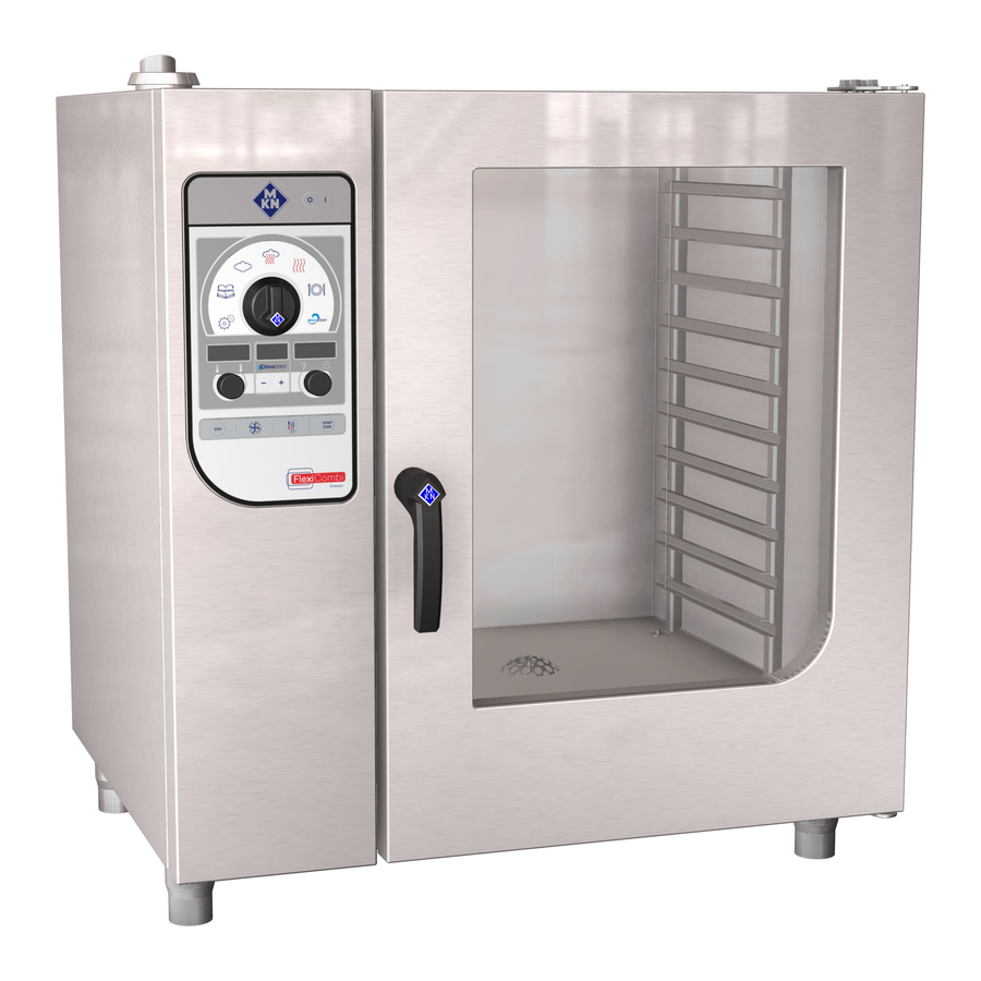
Description of the unit 4 Description of the unit The unit is a hot air steamer, which is suitable for most cooking methods used in commercial kitchens. It can be used with either hot air or unpressurised live steam, either individually, in sequence, or in conjunction with moist or dry heat. -
Page 15: Floor-Standing Unit
Description of the unit 4.1.2 Floor-standing unit Image: Unit with tray trolley a Tray rack k Nameplate b Insulated window l Equipment leg c Door handle m Control unit d Cooking zone door n Housing e Guide rail (right) o Air inlet f Tray trolley p Waste gas connection g Push handle... -
Page 16: Features
Description of the unit 4.2 Features 4.2.1 Characteristics • 1-point core temperature sensor • 4-point core temperature sensor (optional) • Sous-vide core temperature sensor (optional) • Hand shower (optional) • Back-ventilated cooking zone door • Cooking zone door with hygienic glazing (optional) •... -
Page 17: Preheat Bridge For Models 20.15 And 20.21
Description of the unit 4.2.5 Preheat bridge for models 20.15 and 20.21 Image: Preheat bridge In the case of the 20.15 and 20.21 models of Combisteamer, the preheat bridge is attached to the bottom edge of the cooking zone opening, if the cooking zone is heated or cleaned with WaveClean, and if there is no tray trolley in the Combisteamer. -
Page 18: Expanded Cooking Functions
Description of the unit Regeneration Regeneration is a cooking mode, in which the food being cooked can be kept warm and prepared in a temperature range of 30 °C to 155 °C. 4.3.3 Expanded cooking functions Expanded cooking functions can be used to modify individual cooking steps for the particular food being cooked. -
Page 19: Operating, Control And Display Element Functions
Description of the unit 4.4 Operating, control and display element functions Symbo Operating and display element Function On Off "I O" button • Switch unit on "I" • "O" switches off the unit Select knob • Selects the cooking mode, cooking programs, cleaning and settings Steaming symbol •... -
Page 20: Abbreviations In The Displays
Description of the unit Symbo Operating and display element Function Right display • Shows the cooking time or core temperature Core temperature symbol • Indicates that settings for the core temperature can be made here Cooking time symbol • Indicates that settings for the time can be made here Right knob •... -
Page 21: Loading Capacity
Description of the unit Abbreviation Explanation Prot Log number Program number Ready Service Rinse Software Spray Forced rinse STEP Step Step X of Y 4.5 Loading capacity 4.5.1 Loading capacity Tray rack trolley and tray trolley Version Per shelf maximum (kg) Per unit maximum (kg) 6.15 6.21... -
Page 22: Standard Setting Values
Description of the unit 4.6 Standard setting values 4.6.1 Temperature standard setting The setting range for the cooking zone temperature depends on the cooking mode. Cooking mode Standard value Adjustment Alteration (°C) range (°C) increments (°C) Steaming 30 - 130 Combisteaming 30 - 250 Hot air... -
Page 23: Basic Settings
Description of the unit 4.7 Basic settings The unit is already preset, when it is delivered. The values in the following list can be modified. Basic setting Standard Adjustment Explanation value range Password 0 – 500 Individual passwords can be set in this area. - Page 24 Description of the unit Basic setting Standard Adjustment Explanation value range Ready2Cook preheating 0 – 30 % If the unit is fully loaded with a large mass temperature in percent (roasts, loaves of bread), increase the preheating temperature, so that the cooking zone temperature does not drop too suddenly.
-
Page 25: 5 Operating The Unit
Operating the unit 5 Operating the unit 5.1 Operating the unit in an environmentally responsible manner If used correctly, this Combisteamer achieves very low energy consumption. You can assist low energy consumption by: • Avoiding continuous operation - the Combisteamer heats up very quickly, which means that continuous operation is not necessary. -
Page 26: Closing The Single Stage Door Latch
Operating the unit 5.3.2 Closing the single stage door latch Image: Closing the single stage door latch Requirement Door handle in initial position Close the cooking zone door with pressure. The cooking zone door is closed. 5.3.3 Opening the two-stage door latch Image: Opening the two-stage door latch On size 6 and size 10, first rotate the door handle anti- clockwise. -
Page 27: Closing The Two-Stage Door Latch
Operating the unit 5.3.4 Closing the two-stage door latch Image: Closing the two-stage door latch Requirement Door handle in initial horizontal position 1. Close the cooking zone door with pressure. The cooking zone door latches. 2. Rotate the door handle downwards. The cooking zone door is closed. -
Page 28: Loading And Emptying With A Tray Rack Trolley
Operating the unit 4. Leave the cooking zone door slightly ajar. This extends the service life of the door seal. No moisture builds up in the cooking zone. 5.4.2 Loading and emptying with a tray rack trolley Image: Loading and emptying with a tray rack trolley a Tray rack e Tray rack trolley b Push handle... -
Page 29: Loading And Emptying With A Tray Trolley
Operating the unit Emptying with a tray rack trolley 1. Open the cooking zone door. 2. Position the tray rack trolley at the unit. Lock the casters to prevent the trolley's rolling away. 3. Insert the tray rack support plate and secure the tray rack on the plate. -
Page 30: Making The Basic Settings
Operating the unit Emptying with a tray trolley 1. Open the cooking zone door. 2. Insert the push handle into the tray trolley. 3. Retract the tray trolley. 4. Remove all food residues from the drain screen. 5. Leave the cooking zone door slightly ajar. This extends the service life of the door seal. -
Page 31: Basic Functions
Operating the unit 4. Turn the right knob. Set new value. 5. Press the "START STOP" button. Accept changes. 6. Press and hold the "STEP" button for 3 seconds. Changes are saved. "OPt" flashes on the left display. The centre display shows "Stor". 7. -
Page 32: Setting The Cooking Time
Operating the unit 00:45 ° Image: Cooking zone humidity set 5.6.4 Setting the cooking time The cooking time can be set for up to 23 hours and 59 minutes in 1-minute increments. Continuous operation is stopped automatically after 23 hours and 59 minutes. -
Page 33: Displaying Actual Values
Operating the unit 5.6.6 Displaying actual values The actual cooking zone temperature, elapsed cooking time or actual core temperature can be displayed during cooking. Temperature setpoint Turn the left knob. The left display shows the current cooking zone temperature for 5 seconds. Then, the temperature setpoint is displayed. Remaining time or actual core temperature Turn the right knob. -
Page 34: Exporting The Haccp Log
Operating the unit 5.6.10 Exporting the HACCP log Briefly pressing the "START STOP" button transfers the selected logs. Pressing the "START STOP" button for longer (3 seconds) transfers all the available logs. Requirement USB flash drive inserted Registered with password under Settings 1. -
Page 35: Measuring With A 4-Point Core Temperature Sensor
Operating the unit 5.7.1 Measuring with a 4-point core temperature sensor Image: Core temperature sensor with one and four measuring points Insert the core temperature sensor completely into the food being cooked. Insert the core temperature sensor into the thickest point of the food being cooked. -
Page 36: Measuring The Core Temperature When Cooking Frozen Food
Operating the unit When cooking poultry, insert the core temperature sensor into the inside of the leg. 5.7.3 Measuring the core temperature when cooking frozen food When cooking frozen food, measuring with a sous-vide core temperature sensor is not possible. Image: Drilling a hole with a hand drill 1. -
Page 37: Ending The Cooking Mode
Operating the unit 8. Press the "START SROP" button. The indicator light for the "START STOP" button flashes. The number of indicator lights above the Fan speed button displays the speed level. The left display shows the set cooking temperature. The centre display shows the set cooking zone humidity. -
Page 38: Saving User's Own Cooking Program
Operating the unit To correct the settings, press the "STEP" button several times to return to the desired cooking step. Set the values again. 5.9.2 Saving user's own cooking program Requirement Cooking program entered 1. Press the "Programs" button for 3 seconds. "Pro"... -
Page 39: Automatic Cooking
Operating the unit 5.10 Automatic cooking 5.10.1 Selecting the cooking program Requirement No cooking program selected Rotate the Select knob to the Programs symbol. "Pro" appears on the left display. The right display shows the number of the saved cooking program or it shows "1"... -
Page 40: Cancelling The Cooking Program
Operating the unit 5.10.4 Cancelling the cooking program 1. Press the "START STOP" button. The cooking program is cancelled. The indicator light for the selected cooking mode illuminates. The left display shows the preset cooking temperature. The right display shows the preset cooking time. 2. -
Page 41: Multi-Step Cooking Program
Operating the unit 5.11 Multi-step cooking program 5.11.1 Starting Requirement Multi-step cooking program entered Press the "START STOP" button to start the cooking program. The START STOP indicator light flashes until the end of the last program step. The STEP indicator light illuminates. The indicator light for the type of cooking used in the currently active program step illuminates. -
Page 42: Cancelling The Start Time Delay
Operating the unit 4. Press the "START STOP" button. Start-time preselection starts. The indicator light for the "START STOP" button illuminates. The right display shows the remaining time before starting and the colon in the time display flashes. After the remaining time before starting has expired, the set cooking program starts automatically. -
Page 43: Pausing And Finishing Use
Operating the unit 5.13 Pausing and finishing use Switch off the unit during pauses and at end of use. 5.13.1 Perform a hygiene flush after an extended period of idleness For reasons of hygiene, flush the water lines in the unit and on-site water lines before using the unit. -
Page 44: 6 Cleaning And Caring For The Unit
Cleaning and caring for the unit 6 Cleaning and caring for the unit CAUTION Risk of burns from hot surfaces • Allow surfaces to cool prior to cleaning. CAUTION Risk of chemical burns from cleaning agent • Follow the instructions of the cleaning agent manufacturer. •... -
Page 45: Cleaning The Housing
Cleaning and caring for the unit 6.3 Cleaning the housing Requirement Unit switched off and cooled down Clean the housing with warm water and commercially available washing-up liquid. 6.4 Cleaning the door handle, operating elements and control panel ATTENTION Risk of physical damage from improper cleaning •... -
Page 46: Cleaning The Cooking Zone Door
Cleaning and caring for the unit 6.6 Cleaning the cooking zone door CAUTION Risk of burns from hot surfaces • Allow surfaces to cool prior to cleaning. ATTENTION Risk of physical damage from improper cleaning of the surface • Do not use abrasive cleaners or cloths. •... -
Page 47: Cleaning The Steam Outlet
Cleaning and caring for the unit 6.7 Cleaning the steam outlet Image: Cleaning the steam outlet ATTENTION Risk of physical damage from deposits • Check the steam outlet and connected piping for deposits. Use a liquid cleaner containing at most 20% sodium or potassium hydroxide. -
Page 48: Removing Calcium Deposits From The Unit
Cleaning and caring for the unit Requirement Unit and hood disconnected from the electric mains Unit and hood cool 1. Clean the housing daily with warm water and a commercially available cleaner. 2. Push the grease filter upwards. 3. Pull the grease filter on the underside of the hood forward to remove it. -
Page 49: Cleaning The Cooking Zone Automatically With Waveclean (Optional)
Combisteamer. The use of unsuitable cleaning agents often causes damage to units. MKN makes great efforts to be able to offer a cleaning agent, which on the one hand achieves an outstanding cleaning performance, but which on the other hand does not attack and damage the hot air steamer. -
Page 50: Preparing For Cleaning
Cleaning and caring for the unit 6.10.1 Preparing for cleaning ATTENTION Risk of physical damage from improper cleaning • Do not clean the unit with a high-pressure cleaner or water jet. Requirement GN containers, baking trays and grates removed from the cooking zone 1. -
Page 51: Inserting The Cleaning Cartridge
Cleaning and caring for the unit 6.10.3 Inserting the cleaning cartridge Image: Wax seal on the cartridge damaged Use only cleaning cartridges with an undamaged wax seal. If the wax seal is damaged, the cleaner can enter the cleaning circuit prematurely or not dissolve completely, so that complete cleaning is no longer assured. -
Page 52: Starting Automatic Cleaning
Cleaning and caring for the unit 6.10.4 Starting automatic cleaning Requirement Water connection is opened The unit is on Cooking zone temperature at 60 °C Press the "START STOP" button. The button's indicator light flashes. The centre display shows the selected cleaning level. The right display shows the remaining time. -
Page 53: Cleaning The Cooking Zone Semi-Automatically
Cleaning and caring for the unit 6.11 Cleaning the cooking zone semi-automatically 6.11.1 Preparing the cooking zone ATTENTION Risk of physical damage from improper cleaning • Do not clean the unit with a high-pressure cleaner or water jet. Requirement GN containers, baking trays and grates removed from the cooking zone 1. -
Page 54: Rinsing The Cooking Zone
Cleaning and caring for the unit 5. The softening process starts automatically. The right display shows the remaining softening time. 6. Softening time elapsed. "SPr" flashes on the right display. "CLE" appears on the left display. 7. Put on protective clothing, safety goggles and protective gloves. 8. -
Page 55: Swinging The Air Diverter Open And Closed
Cleaning and caring for the unit 3. Open the cooking zone door and leave it ajar until the unit is used again. This extends the service life of the door seal. No moisture builds up in the cooking zone. 6.12 Swinging the air diverter open and closed CAUTION Pinch hazard from rotating fan •... -
Page 56: Inspecting The Unit
Cleaning and caring for the unit 6.13 Inspecting the unit 6.13.1 Performing a visual inspection ATTENTION Risk of physical damage from improper inspection • Inspect in accordance with the inspection intervals. • Have inspections performed by a capable user. • In the event of damage or signs of wear, contact customer service immediately and stop using the unit. -
Page 57: 7 Troubleshooting
Troubleshooting 7 Troubleshooting Image: Left, centre and right displays If an error occurs during operation, the error group and the error number within the group are displayed. • The left display shows the error group. • The right display flashes the error number. For a remedy, give customer service the error group and error number displayed. - Page 58 Troubleshooting Fault Fault no. Failure Possible causes Remedy group Top cooking zone sensor is • Sensor failure • The second cooking zone defective sensor is used as a sub- stitute sensor Bottom cooking zone sensor • Sensor failure • Contact Customer service is defective Emergency mode due to •...
-
Page 59: Nameplate
Troubleshooting Fault Fault no. Failure Possible causes Remedy group 13 / 14 / Wiring fault in gas solenoid • Contact Customer service valve / at top / at bottom 16 - 24 Internal gas fault • Contact Customer service 25 / 26 / Fault in communication with •... -
Page 60: Dispose Of Unit In An Environmentally Responsible Manner
Dispose of unit in an environmentally responsible manner 8 Dispose of unit in an environmentally responsible manner The unit has been designed to provide a lifetime of 10 years with average use. Do not dispose of unit or the unit's components together with non- recyclable waste. -
Page 61: 9 Manufacturer's Declaration
Manufacturer's declaration 9 Manufacturer's declaration EC Declaration of Conformity Manufacturer MKN Maschinenfabrik Kurt Neubauer GmbH & Co. KG • Halberstädter Straße 2a • 38300 Wolfenbüttel, Germany We hereby declare, that the following product: Description of the unit Unit for cooking food in commercial applications Designation / Unit type FlexiCombi gas combisteamer / FKGCOD... - Page 62 Manufacturer's declaration EC Declaration of Conformity Adduced basis for verification EN 203-1:2014 EN 203-2-2:2006 EN 203-3:2009 EN 55014-1:2006 EN 55014-2:1997 EN 60335-2-102:2006 EN 61000-3-2:2014 EN 61000-3-3:2013 EN 60335-1:2002 + A11:2004 + A1:2004 + A12:2006 + A2:2006 + A13:2008 + A14:2010 + A15:2011 The manufacturer bears the sole responsibility for issuing this Declaration of Conformity.
- Page 64 www.mkn.eu...
Need help?
Do you have a question about the FlexiCombi Classic Series and is the answer not in the manual?
Questions and answers
Error code 702 in MKN Flexicombi microwave oven
Flexi Combi classic FKECOD121C0022