Table of Contents
Advertisement
Advertisement
Table of Contents

Related Manuals for MKN FlexiCombi MagicPilot


Summary of Contents for MKN FlexiCombi MagicPilot
- Page 1 Read the operating instructions prior to commissioning Installation instructions Combisteamer Unit Type of energy Unit type Model FlexiCombi MagicPilot Electric Tabletop unit FKECOD615 FKECOD621 FKECOD115 FKECOD121 Floor-standing unit FKECOD215 FKECOD221 10000011175AINBEA en-GB...
- Page 2 Fax +49 5331 89-280 Internet www.mkn.com Copyright All rights to text, graphics and pictures in this documentation are held by MKN Maschinenfabrik Kurt Neubauer GmbH & Co. KG. Distribution or duplication is only permitted with the prior written consent of MKN.
-
Page 3: Table Of Contents
Directory of contents 1 Introduction ................. 5 1.1 About this manual ................ 5 1.1.1 Explanation of signs .................. 6 1.2 Staff qualification ................ 7 1.3 Use of the unit ................... 7 1.4 Warranty .................... 7 2 Safety information .............. 8 3 Description of the unit ............. 10 3.1 Overview of the unit ............... 10 3.2 Equipment and connection data ... - Page 4 Directory of contents 6.5.2 Connecting softened tap water to both connections ....... 45 6.6 Making the wastewater connection .......... 46 6.6.1 Determining the type of connection to the sewer system ...... 46 6.6.2 Connecting the wastewater line to a permanent connection .... 47 6.6.3 Connecting a wastewater line with an unobstructed discharge ....
-
Page 5: 1 Introduction
Introduction 1 Introduction 1.1 About this manual The instruction manual is part of the unit and contains information on safe installation of the unit. Observe and adhere to the following instructions: • Read the instruction manual in its entirety prior to installation. •... -
Page 6: Explanation Of Signs
Introduction 1.1.1 Explanation of signs DANGER Imminent threat of danger Failure to comply will lead to death or very severe injuries. WARNING Possible threat of danger Failure to comply can lead to death or very severe injuries. CAUTION Dangerous situation Failure to comply can lead to slight or moderately severe injuries. -
Page 7: Staff Qualification
Introduction 1.2 Staff qualification Explanation of qualification Skilled staff • Skilled staff are those, who due to their profes- sional training, knowledge and experience as well as their knowledge of the relevant standards can assess the tasks given to them and recognize any possible dangers. -
Page 8: 2 Safety Information
Safety information 2 Safety information The unit complies with applicable safety standards. Residual risks associated with operation or risks resulting from incorrect operation cannot be ruled out and are mentioned specifically in the safety instructions and warnings. The installer must be familiar with regional regulations and observe them. - Page 9 Safety information Setup Risk of property damage and personal injury from improper setup • Ensure that the installation area has adequate load-bearing capacity. • Wear safety shoes and protective gloves. Electrical connection Risk of fire from improper connection • Observe applicable regional regulations of the electrical utility. •...
-
Page 10: 3 Description Of The Unit
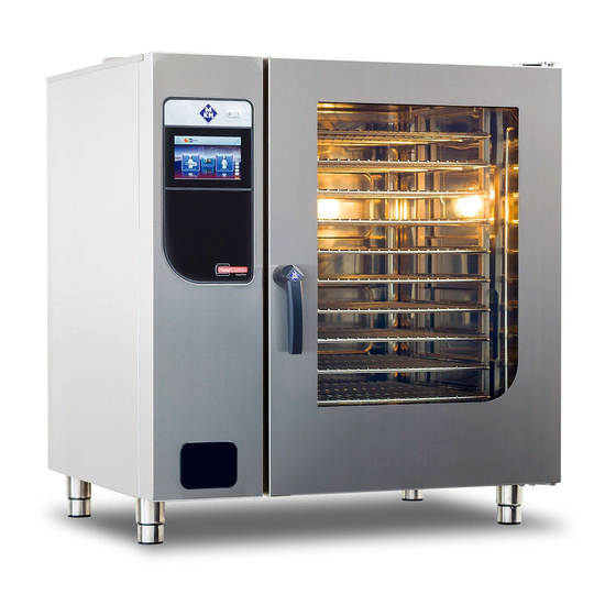
Description of the unit 3 Description of the unit 3.1 Overview of the unit Image: Unit with tray rack trolley a Tray rack k Nameplate b Insulated window l Base frame (optional) c Door handle m Equipment leg d Cooking zone door n Control unit e Tray rack trolley (optional) o Housing... - Page 11 Description of the unit Image: Unit with tray trolley a Tray rack j Hand shower (optional) b Insulated window k Nameplate c Door handle l Equipment leg d Cooking zone door m Control unit e Guide rail (right) n Housing f Tray trolley o Air inlet g Push handle...
-
Page 12: Equipment And Connection Data
Description of the unit 3.2 Equipment and connection data • All voltages listed below are technically available. • For some voltages, however, the implementation must be agreed with the manufacturer. • The voltage for which the device is designed is indicated on the nameplate. - Page 13 Description of the unit Size Power connection Protection class IPX5, IPX6 (optional) Type of connection 3PE / AC 50/60 Hz, 3NPE / AC 50/60 Hz Voltage (V) Connected load (kW) 10.1 16.3 14.7 25.5 29.4 50.9 Fuse (A) 3 x 35 3 x 50 3 x 50 3 x 80 3 x 100...
- Page 14 Description of the unit Size Softened tap water connection Water type Softened tap water, cold Residual hardness CaCO < 1 (5,6) (mmol/l (°dH)) Chloride Cl (mg/l) < 100 Iron Fe (mg/l) < 0.2 Connection pressure (kPa 200 (2) — 600 (6) (bar)) Connection (") R 3/4...
- Page 15 Description of the unit Floor fastening Mandatory for the following types of unit FKECOD615 Only in conjunction with base cabinet and base frame FKECOD621 FKECOD115 FKECOD121 FKECOD121-621 Only in conjunction with stacking kit FKECOD115-621 FKECOD121-615 FKECOD115-615 FKECOD215 on castors FKECOD221 on castors Basic control setting Basic setting Parameter...
- Page 16 Description of the unit Basic setting Parameter Standard Adjustment Explanation value range Kitchen control Disabled 0 = Disabled Indicates whether the Kitchen system management system is being used. 1 = Active Ethernet 0 = Ethernet Type of signal transmission (interface) 1 = Serial 1188 0 —...
-
Page 17: 4 Transporting The Unit
Transporting the unit 4 Transporting the unit CAUTION Risk of property damage and personnel injury from tipping equipment • Do not linger next to or behind raised equipment. • Move raised equipment carefully. CAUTION Risk of property damage and personnel injury from tipping unit •... -
Page 18: Transporting The Unit To The Installation Site
Transporting the unit 4.1 Transporting the unit to the installation site Image: Lengthwise and crosswise transport on pallet Use suitable transport means to move the unit to the installation site. 4.2 Unpacking the unit CAUTION Risk of injury from sharp edges •... -
Page 19: 5 Setting Up The Unit
Setting up the unit 5 Setting up the unit WARNING Risk of burns from spraying hot fat • Set up deep fat fryers outside the range of the hand shower. WARNING Danger of the unit tipping over on castors If the unit is tilted on castors, it may tip over and seriously injure you. -
Page 20: Maintaining Minimum Clearances
Setting up the unit 5.1 Maintaining minimum clearances Image: Minimum clearances to walls, ceiling or units D ** All dimensions in mm * Depending on the kitchen ventilation system and the material composition of the ceiling ** Recommended for service work 500 mm The following clearances from walls, ceilings or other equipment must be maintained when setting up the unit: •... - Page 21 Setting up the unit ATTENTION Material damage to the device control due to excessive ambient temperatures Minimum distance to devices with large heat radiation 510 mm. These include, for example: - Gas stoves - Gas griddle plates - Grills - Deep fryers If the mentioned distances to devices with high heat radiation cannot be implemented, a heat protection plate can also be used for the following devices.
-
Page 22: Lifting The Unit Off The Pallet
Setting up the unit 5.2 Lifting the unit off the pallet CAUTION Risk of property damage and personnel injury from tipping equipment • Do not linger next to or behind raised equipment. • Move raised equipment carefully. ATTENTION Risk of physical damage from lifting the unit incorrectly •... -
Page 23: Setting Up The Unit On A Base Frame
Setting up the unit 5.4 Setting up the unit on a base frame Image: Setting up the unit on a base frame a Lifting fork d Stud bolt b Waste trap on the unit e Equipment leg c Base frame f Unit Requirement The base frame must carry the weight of the unit Base frame levelled... -
Page 24: Installing The Support Rack
Setting up the unit 5.4.1 Installing the support rack Depending on the version, the base frame can be equipped with a support rack. The support rack is used to hold containers, metal trays and grates. Image: A Stop profile, B Support rack a Stop profile c Outboard support rack b Pin... - Page 25 Setting up the unit Aligning tray trolley Requirement The floor under and in front of the unit is flat 1. Level the unit by screwing the equipment legs in or out. 2. If the floor conditions are poor, insert spacers on the casters of the tray trolley.
-
Page 26: Fastening The Unit To The Floor
Setting up the unit 7. Move the tray trolley into the unit until it stops and check the alignment. The casters of the inserted tray trolley should no longer have floor contact. 8. Remove the push handle. 9. Close the cooking zone door. 10.Fill out the Commissioning report. - Page 27 Setting up the unit A special fastening set, which secures the unit against tilting, is supplied by the manufacturer or is available as an accessory. The fastening set comprises two floor fastenings and all the necessary components for screwing or bonding them to the floor. The unit or base frame is fastened with two floor fastenings as shown in the drawing.
- Page 28 Setting up the unit 9. Screw the base plate to the floor using the enclosed dowels and fastening screws. 10.Ensure that, after the fastening screws have been inserted, the floor seal is restored again. 11.Put the holding plate onto the base plate and fasten it with the cap nuts.
-
Page 29: Securing The Unit Against Sliding
Setting up the unit 6. Put the holding plate onto the base plates and fasten with the cap nuts. 7. Fill out the Commissioning report. 5.6.2 Securing the unit against sliding If required, a Combisteamer size 2XX can be secured against sliding (optional). -
Page 30: Unit On Castors: Attach Both Castor Stops To The Floor
Setting up the unit 3. Using suitable lifting equipment, move the unit away until the drill holes can be made in the floor. 4. Drill the holes in the diameter of the dowel sufficiently deep into the floor. 5. Carefully move the unit to the installation position. 6. -
Page 31: Unit On Castors: Secure Unit To The Wall
Setting up the unit 5.7 Unit on castors: Secure unit to the wall Requirement Wall must be designed for a tensile force of at least 0.6 kN. The safety rope for securing must be shorter than the connecting lines of the unit. 1. -
Page 32: 6 Connecting The Unit
Connecting the unit 6 Connecting the unit DANGER Risk of personal injury and physical damage from electric shock • Prior to working on the unit, ensure that the unit has been disconnected from the mains. • Do not operate the unit with the housing open. CAUTION Risk of injury from sharp edges •... -
Page 33: Making The Power Connection
Connecting the unit Attaching side wall ATTENTION Risk of physical damage from leaky housing • Check seals when attaching the housing parts. • Replace damaged gaskets. 1. Insert the top edge of the side wall. 2. Carefully push the bottom of the side wall inwards. 3. - Page 34 Connecting the unit Permanent connection CAUTION Risk of property damage and personal injury from improper installation • In the case of a permanent electrical connection, install an all-phase disconnect switch with at least 3 mm contact opening before the unit. Install an all-phase disconnect switch if the unit will be connected permanently to the electric mains.
-
Page 35: Matching The Unit To The Connection Voltage
Connecting the unit Due to special electronic components, the unit generates a small fault current. To ensure that the residual current device does not trip during normal operation, each unit must have its own residual current device. Potential equalisation Image: Symbol for potential equalisation The unit can be included in a potential equalisation system by means of appropriately sized wiring. - Page 36 Connecting the unit Transformer Power supply unit Currently, the units are equipped with a transformer or a power supply, depending on availability. The adjustment of the supply voltage described below may only be necessary for units with a transformer. No adjustment is necessary for units with a power supply unit. When the unit is delivered, it is preset to a certain connection voltage or voltage range.
-
Page 37: Connecting The Power Connection Cable
Connecting the unit Image: A Transformer position T0, only for unit without neutral wire; B Transformer connection Requirement Unit not live Left side wall removed 1. Measure the connection voltage with a suitable measuring device. The voltage range must match that on the nameplate. If there are voltage fluctuations, the maximum expected voltage must be taken into account. - Page 38 Connecting the unit Image: Connecting the electric power cable a Connection terminals c Electric power cable b Cable tie d Cable gland Requirement Unit not live Power connection cable not live Unit matched to the connection voltage Side wall open 1.
-
Page 39: Connecting The Power Optimisation System
Connecting the unit 6.2.3 Connecting the power optimisation system DANGER Risk of personal injury and physical damage from electric shock • Prior to working on the unit, ensure that the unit has been disconnected from the mains. • Do not operate the unit with the housing open. DANGER Risk of personal injury and physical damage from electric shock... -
Page 40: Connecting To The Potential Equalisation Circuit
Connecting the unit 6.2.4 Connecting to the potential equalisation circuit Image: Connecting the potential equalisation circuit 1. Run and attach potential equalisation line to the identified terminal. 2. Fill out the commissioning report. 6.3 Connecting the kitchen management system The units can be connected with a RJ45 plug to a kitchen management system. - Page 41 Connecting the unit Image: Connecting the kitchen management system a RJ45 socket d Cable tie b RJ45 plug e Ferrite ring c Network cable Requirement Unit not live Housing opened 1. Pull the network cable into the unit through the cable gland. 2.
-
Page 42: Making The Basic Control Setting
Connecting the unit 6.4 Making the basic control setting Image: Main menu a Main menu d "Equipment functions" button b FlexiHelp button e Back button c Language selection 6.4.1 Changing the basic control setting By entering the password "2100", the basic settings for the installation can be displayed and changed. -
Page 43: Making The Water Connection
Connecting the unit 6.5 Making the water connection Installation work with tap water Installation work on tap water lines and the unit may only be performed by a specialist company, which is approved by the water utility company in the particular region. The applicable regional regulations, standards and guidelines must be observed, as well as the connection conditions imposed by the water utility company responsible. -
Page 44: Connecting The Tap Water Connection Line
Connecting the unit 6.5.1 Connecting the tap water connection line Image: Water connection a Soft water d Tap water connection b Backflow preventer e Tap water connection line c Soft water connection f Tap water Requirement Water pressure complies with the specified range (see "Equipment and connection data") Backflow preventer installed The connection lines are pressure-tight and suitable for tap water... -
Page 45: Connecting Softened Tap Water To Both Connections
Connecting the unit 6.5.2 Connecting softened tap water to both connections If only softened tap water is available at the installation site, use a T- piece to connect both water connections on the unit to each other. Image: Connecting softened tap water to both connections a Softened tap water e Tap water connection b Backflow preventer... -
Page 46: Making The Wastewater Connection
Connecting the unit 6.6 Making the wastewater connection ATTENTION Overflow of the device through an externally mounted siphon Combi steamers have an integrated siphon. An additional, external siphon without ventilation of the drain line will cause the unit to overflow in these combi steamers. Therefore, do not connect an external siphon without ventilation to the waste water connection. -
Page 47: Connecting The Wastewater Line To A Permanent Connection
Connecting the unit 6.6.2 Connecting the wastewater line to a permanent connection Image: Wastewater line to a permanent connection a Wastewater connection d Wastewater system b Wastewater line e Pipe clamp c Siphon f Vacuum breaker If a waste trap is installed in the wastewater system, a vacuum breaker must be installed in the wastewater line. -
Page 48: Connecting A Wastewater Line With An Unobstructed Discharge
Connecting the unit 6.6.3 Connecting a wastewater line with an unobstructed discharge Image: Connecting a wastewater line with an unobstructed discharge a Wastewater connection d Sewer system b Wastewater line e Sewer system waste trap c Funnel waste trap f Discharge funnel Connect only the discharge funnel if a wastewater trap is installed in the wastewater system. -
Page 49: Making The Exhaust Air Connection
Connecting the unit 6.7 Making the exhaust air connection When setting up the unit under a ventilation system, observe the regional regulations for heating, ventilation and air conditioning systems. ATTENTION Risk of physical damage from fouling of the exhaust air ducts •... -
Page 50: 7 Testing The Function
Testing the function 7 Testing the function DANGER Risk of personal injury and physical damage from unsuccessful operational check • Do not put the unit into service. • Contact customer service. Requirement Power connection made Water connection made Wastewater connection made Unit is aligned Unit cleaned 7.1 Checking the controls... -
Page 51: Heating The Unit Up And Rinsing It Out
Testing the function 7.3 Heating the unit up and rinsing it out 1. Switch on the unit. 2. Tap the "Manual cooking" button. Manual cooking menu is displayed. 3. Run the "Steaming" cooking mode for 15 minutes at 100 °C. 4. -
Page 52: 8 Putting The Unit Into Service
Putting the unit into service 8 Putting the unit into service If the unit is not put into service immediately after being connected and the function check, all inspections must be repeated. Requirement Power connection made Water connection established Wastewater connection established Exhaust connection made ... -
Page 53: Filling Out The Commissioning Report
Putting the unit into service 8.2 Filling out the Commissioning report General Enter the data on the nameplate. Type Electrical connection Designation Item no.: (if available) Obvious damage to the unit? What and where? Unit levelled? General Is it necessary to secure the unit against tipping or slipping? If so, how was it secured? Secured against tilting Secured against sliding... - Page 54 Putting the unit into service Basic control setting Voltage set in the control. Voltage: Set volume unit fl.oz. (Imperial) fl.oz. (U.S.) Power optimisation system set? Set water filter maintenance No maintenance message maintenance message at Has kitchen management system been set? Unit address: Water connection Connection pressure within indicated range?
- Page 55 Putting the unit into service Final notes Was the unit put into service? Comments: Operator trained? Electrical installation was provided by: Signature Company Installer City, date The connection to a kitchen management system was made by: Signature Company Installer City, date The water and wastewater installation was provided by: Signature Company...
- Page 56 Putting the unit into service Installation instructions...
- Page 60 www.mkn.com...
Need help?
Do you have a question about the FlexiCombi MagicPilot and is the answer not in the manual?
Questions and answers