Chapters
Table of Contents

Related Manuals for MKN FlexiCombi Classic Series


Summary of Contents for MKN FlexiCombi Classic Series
- Page 1 Read the operating instructions prior to commissioning Installation instructions Combisteamer Unit Model Type of energy Device type FlexiCombi Classic 6.15, 6.21, 10.15, 10.21 Countertop unit 20.15, 20.21 Floor-standing unit 10014471-0AIBE-A en-GB...
- Page 2 Fax +49 53 31 / 89-280 Copyright All rights to text, graphics and pictures in this documentation are held by MKN Maschinenfabrik Kurt Neubauer GmbH & Co. KG. Distribution or duplication is only permitted with the prior written consent of MKN.
-
Page 3: Table Of Contents
Directory of contents 1 Introduction ................. 5 1.1 About this manual ................ 5 1.1.1 Explanation of signs .................. 6 1.2 Use of the unit ................... 7 1.3 Warranty .................... 7 2 Safety information .............. 8 3 Description of the unit ............. 11 3.1 Overview of the unit ............... 11 3.2 Planning drawing ................ ... - Page 4 Directory of contents 6.4.1 Opening the Setting menu ............... 35 6.4.2 Changing the basic control settings ............ 36 6.5 Making the water connection ............ 36 6.5.1 Connecting hard and soft water .............. 37 6.5.2 Connecting soft water twice .............. 38 6.6 Making the wastewater connection .......... 38 6.6.1 Identifying the cleaning system ...
-
Page 5: 1 Introduction
Introduction 1 Introduction 1.1 About this manual The instruction manual is part of the unit and contains information on safe installation of the unit. Observe and adhere to the following instructions: • Read the instruction manual in its entirety prior to installation. •... -
Page 6: Explanation Of Signs
Introduction 1.1.1 Explanation of signs DANGER Imminent threat of danger Failure to comply will lead to death or very severe injuries. WARNING Possible threat of danger Failure to comply can lead to death or very severe injuries. CAUTION Dangerous situation Failure to comply can cause minor or moderate injuries. -
Page 7: Use Of The Unit
Introduction 1.2 Use of the unit This unit is intended to be used solely for commercial purposes, particularly in commercial kitchens. This unit is not intended for the US and Canadian markets. It is not permitted to be used there. 1.3 Warranty The warranty is void and safety is no longer assured in the event of: •... -
Page 8: 2 Safety Information
Safety information 2 Safety information Ensuring conformity with Observe applicable international, European and national laws, standards regulations, standards and directives for the unit when transporting, setting up and connecting it. Improper installation Risk of property damage and personal injury from improper installation •... - Page 9 Safety information Setup Risk of property damage and personal injury from improper setup • Ensure that the installation area has adequate load-bearing capacity. • Wear safety shoes and protective gloves. Electrical connection Risk of fire from improper connection • Observe applicable regional regulations of the electrical utility. •...
- Page 10 Safety information Additional connection work Risk of physical damage and personal injury from improper connection • Prior to working on the unit, switch off the unit, disconnect the unit from the mains and prevent power from being switched on again. Check to ensure absence of voltage.
-
Page 11: 3 Description Of The Unit
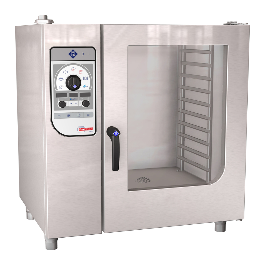
Description of the unit 3 Description of the unit 3.1 Overview of the unit Image: Gas-FlexiCombi Classic, unit size 10 a Cooking zone door h Wastewater connection b Door handle i Opening for power connection c Operating elements j Gas connection on unit d Hand shower k Potential equalisation connection e Equipment leg, vertically ad-... - Page 12 Description of the unit Image: Gas-FlexiCombi Classic, size 20 a Cooking zone door i Opening for power connection b Door handle j Gas connection on unit c Operating elements k Potential equalisation connection d Hand shower l Air intake connection fitting e Equipment leg, vertically ad- m Waste gas connection, burner 2 justable...
-
Page 13: Planning Drawing
Description of the unit 3.2 Planning drawing Image: Unit sizes 6 and 10 Image: Unit size 20 Unit size 6.15, 6.21 1020 1640 10.15, 10.21 1020 1060 1640 20.15, 20.21 1075 1960 a-h= mm Installation instructions... -
Page 14: Equipment And Connection Data
Description of the unit 3.3 Equipment and connection data Unit size 6.15 6.21 10.15 10.21 20.15 20.21 Dimensions Unpacked unit 102 x 80 x 102 x 80 x 102 x 80 x 102 x 80 x 108 x 82 x 108 x 82 x Length x width x height (cm) Packaged unit... - Page 15 Description of the unit Unit size 6.15 6.21 10.15 10.21 20.15 20.21 Rated heat input (kW) Gas type The gas type for which the unit is set is indicated on the gas type supplemental label. Gas connection (inches) R 3/4, male thread EN 10226-1 Connection pressure (mbar) Natural gas 2H, 2E, 2L, 2LL ** Connection pressure (mbar)
-
Page 16: Connection Pressure
Description of the unit 3.3.1 Connection pressure Gas connection pressure Gas type Connection pressure (mbar) Connection pressure range (mbar) Germany: Natural gas 2H, 2E, 2L (LL) 17 (18) – 25 Liquefied gas 3B/P, 3P 42.5 – 57.5 Europe: Natural gas 2E, 2H, (LL) 17 (18) –... -
Page 17: Exhaust Gas Values
Description of the unit 3.3.3 Exhaust gas values Output Unit size (vol. %) * (hPa) ** CO (ppm) *** offset type Range optimal Range optimal Range optimal Natural All units 8.6 - 9.6 0 - 1000 <100 6.1, 6.2 0.5 - 1.0 -0.8 - 0 -0.55 10.1, 10.2,... -
Page 18: Status Messages
Description of the unit 3.3.5 Status messages Burner operation Display Meaning HI = High output G1F1 CO2 = CO measurement G1 = Gas supply open (gas solenoid valve open) F1 = Flame present (burner on) 85°C = Current cooking zone temperature 85°C 2800 CO2 = CO... -
Page 19: 4 Transporting The Unit
Transporting the unit 4 Transporting the unit 4.1 Transport information Image: Crossing a grate with the tray trolley Prior to transporting the unit to the installation site, ensure that: • The route has adequate load-bearing capacity; place rails or metal plates underneath if necessary. -
Page 20: Transporting On A Pallet
Transporting the unit 4.2.1 Transporting on a pallet 1. Move the pallet truck under the pallet. 2. Raise the unit on the pallet. Image: Transporting the unit on a pallet 3. Move the unit to the installation site. 4.2.2 Transporting without a pallet ATTENTION Risk of physical damage from improper lifting of the unit •... - Page 21 Transporting the unit Image: Transporting unit sizes 6 and 10 without a pallet 4. Move the unit to the installation site. Unit size 20 Requirement Packaging removed except for the pallet 1. Move the pallet truck under the guide rails of the unit from the right.
-
Page 22: Transporting By Raising And Lowering
Transporting the unit 4.2.3 Transporting by raising and lowering DANGER Risk of fatal injury from falling unit • Do not linger under a suspended load. • Cordon off hazard area in compliance with regulations. ATTENTION Risk of physical damage from tightened lifting straps •... -
Page 23: 5 Setting Up The Unit
Setting up the unit 5 Setting up the unit The supply air and exhaust gas openings in the unit must not be obstructed or closed. WARNING Risk of burns from spraying hot fat • Set up deep fat fryers outside the range of the hand shower. CAUTION Risk of crushing from improper setup •... -
Page 24: Placing The Unit On The Equipment Legs
Setting up the unit Requirement Unit unpacked Protective film removed Unit cleaned Image: Lifting the unit off the pallet 1. Slide the forks of the pallet truck under the unit and to the right of the waste trap. 2. Lift the unit off the pallet. 5.2 Placing the unit on the equipment legs Requirement The floor must carry the weight of the unit 1. -
Page 25: Setting Up The Unit On A Work Surface
Setting up the unit 5.3 Setting up the unit on a work surface Requirement The base frame must carry the weight of the unit Base frame levelled Base frame set up in accordance with the planning drawing Planning drawing 1. Lift the unit. Image: Setting up the unit on a work surface a Lift fork d Stud bolt... -
Page 26: Aligning The Unit
Setting up the unit 3. Clean the adhesion surface for the sticker. 4. Attach the sticker to the cooking zone door at a height of 1.6 m. 5.4 Aligning the unit 5.4.1 Aligning countertop units Requirement Base frame levelled 1. Place a spirit level on the unit. 2. - Page 27 Setting up the unit Image: Aligning the unit with the tray trolley a Tray trolley d Equipment leg b Distance between roller and sup- e Roller port rail c Support rail 3. Place the tray trolley against the support rails. 4.
-
Page 28: Maintaining Minimum Clearances
Setting up the unit 5.5 Maintaining minimum clearances 500 - 800 Image: FlexiCombi minimum clearances a Ceiling c Deep-fat fryer b Baking oven The following clearances from walls, ceilings or other equipment must be provided when setting up the unit: •... -
Page 29: 6 Connecting The Unit
Connecting the unit 6 Connecting the unit 6.1 Opening and closing the housing DANGER Risk of personal injury and physical damage from electric shock • Prior to working on the unit, ensure that the unit has been disconnected from the mains. •... -
Page 30: Checking The Supply Air And Exhaust Gas Routing
Connecting the unit Attaching the side panel ATTENTION Risk of physical damage from squeezing the lines When attaching the side panel, make sure that no lines are squeezed. 1. Insert the top edge of the side panel. ATTENTION Risk of physical damage from a loose side panel •... - Page 31 Connecting the unit • Routing of the supply air and exhaust gas must not impair proper operation (for example by underpressure). • A safety device must ensure that gas can be supplied only when the ventilation system is switched on. •...
-
Page 32: Making The Electrical Connection
Connecting the unit 2. Ensure that the supply air and exhaust gas routing is unobstructed. 3. Ensure that supply air and exhaust gas routing functions properly. 4. Fill out the commissioning report. 6.3 Making the electrical connection 6.3.1 Notes regarding the electrical connection Installation work Electrical installation work must be performed by a licensed electrician. -
Page 33: Connecting The Electric Power Cable To The Unit
Connecting the unit Plug-in connection CAUTION Risk of property damage and personal injury from improper installation • The plug-in connection must be readily accessible. If the unit will be connected to the electric mains by a plug, use a plug and socket that comply with IEC 60309. -
Page 34: Connecting To The Potential Equalisation Circuit
Connecting the unit Image: Gas Combisteamer terminal assignment L1 Phases PE Protective earth N Neutral conductor X1 Mains connection Requirement Electrical connection to the unit matches the information on the nameplate Housing open Electric power cable sufficiently long 1. Insert the electric power cable into the unit through the cable gland. -
Page 35: Making The Basic Control Settings
Connecting the unit 6.4 Making the basic control settings By entering the password "2100", the basic settings for the installation can be displayed and changed. 6.4.1 Opening the Setting menu Programs Clean ClimaSelect START STEP STOP Image: FlexiCombi Classic control panel a On Off button g "START STOP"... -
Page 36: Changing The Basic Control Settings
Connecting the unit 6.4.2 Changing the basic control settings 1. Press the "START STOP" button. The left display flashes the first number of the basic setting; refer to the of basic settings table. The centre display shows "OPt". The right display shows the first set value. 2. -
Page 37: Connecting Hard And Soft Water
Connecting the unit 6.5.1 Connecting hard and soft water The unit is equipped with a connection for: • Soft water for generating steam • Hard water for cooling, rinsing and WaveClean CAUTION Hygiene risk from contaminated drinking water • The connection to the drinking water supply must be equipped with a backflow preventer. -
Page 38: Connecting Soft Water Twice
Connecting the unit 6.5.2 Connecting soft water twice If only a soft water connection is available at the installation site, the hard water connection and the soft water connection must be connected by means of a T-piece. Image: Connect saltwater connection twice a Soft water tap e Hard water connection b Backflow preventer... -
Page 39: Identifying The Cleaning System
Connecting the unit 6.6.1 Identifying the cleaning system FlexiCombi Classic units can be equipped with either an automatic or manual cleaning system. The pictogram on the control panel shows which cleaning system is installed. Cleaning system Sewer system connection Permanent connection, with on-site waste trap: Install a vacuum breaker in the Automatic cleaning system... -
Page 40: Connecting The Wastewater Line To The Discharge Funnel
Connecting the unit 1. Install wastewater line up to connection to the sewer system . 2. Secure the wastewater line with clamps. 3. Fill the waste trap on the unit with drinking water. 6.6.3 Connecting the wastewater line to the discharge funnel Image: Connecting the wastewater line to the discharge funnel a Wastewater connection d Wastewater system... -
Page 41: Connecting The Gas
Connecting the unit 6.7 Connecting the gas 6.7.1 Notes about the gas connection Gas installation work on the gas system and the unit may be performed only by a licensed tradesman approved by the gas utility. Observe the applicable regional regulations of the gas utility. DANGER Risk of fatal injury from operating the unit with the wrong gas type... -
Page 42: Description Of The Gas Connection
Connecting the unit Shut-off device The unit or the gas connection line must be equipped with a thermally activated shut-off. In strictly commercial buildings, a thermally activated shut-off is not necessary if the objective of providing fire and explosion safety is achieved by other means. 6.7.2 Description of the gas connection Image: FlexiCombi gas connection a Gas shut-off valve... - Page 43 Connecting the unit ATTENTION Risk of physical damage from excessively high pressure • When opening the gas shut-off valve on the unit, ensure that the pressure in the gas connection line is <150 mbar. • If the pressure is >150 mbar, close the gas supply, reduce the pressure in a technically correct manner and notify the gas utility.
-
Page 44: Checking For Leaks
Connecting the unit 6.7.4 Checking for leaks Requirement Gas connection line connected Left side wall removed DANGER Risk of explosion and fire from leaking, gas-conducting parts • Check the gas connection line and all gas-conducting parts for leaks at the operating pressure. •... -
Page 45: Checking The Connection Pressure
Connecting the unit 5. Fill out the commissioning report. 6.7.5 Checking the connection pressure DANGER Risk of personal injury and physical damage from electric shock • Inspection and adjustment work that can be carried out only with the housing open and the unit under power must be performed only by electrically trained technical personnel. -
Page 46: Checking The Basic Gas Setting
Connecting the unit DANGER Risk of explosion and fire from escaping gas • When bleeding air from or degassing the gas system and the unit, ensure that the air and gas are discharged to the outside in a technically correct manner and without creating a risk. - Page 47 Connecting the unit Checking the rated heat input WARNING Risk of poisoning from exhaust gases • Ensure that exhaust gases are discharged properly and that the necessary amount of combustion air is supplied. • Ensure that a maximum CO content of < 0.1 vol. % or < 1000 ppm is achieved in undiluted exhaust gas.
-
Page 48: Measure The Co
Connecting the unit 8. Press the Ready2Cook button. The left display shows the current temperature in the cooking zone. The centre display shows the selected burner "-1-" (only unit size 20). The right display shows the current status of the burner ("G1F1"). - Page 49 Connecting the unit 14.Using the left knob, set the burner to low output ("LO"). The left display flashes "LO". The centre display shows "CO2". 15.Using the right knob, select the first burner "-1-" (only unit size 20). The right display flashes "-1-". 16.Press the "START STOP"...
- Page 50 Connecting the unit Checking the primary air quantity Requirement Left side wall removed DANGER Risk of personal injury and physical damage from electric shock • Inspection and adjustment work that can be carried out only with the housing open and the unit under power must be performed only by electrically trained technical personnel.
- Page 51 Connecting the unit Checking the exhaust gas values WARNING Risk of poisoning from exhaust gases • Ensure that exhaust gases are discharged properly and that the necessary amount of combustion air is supplied. • Ensure that a maximum CO content of < 0.1 vol. % or < 1000 ppm is achieved in undiluted exhaust gas.
-
Page 52: Adjusting The Basic Gas Setting
Connecting the unit 8. The indicator light in the "START STOP" button goes out; the burner is switched off. 9. Switch off the unit. 10.Fill out the commissioning report. 6.7.7 Adjusting the basic gas setting Requirement Gas connection line connected Check for leaks outside the unit conducted Connection pressure checked Check for leaks inside the unit conducted... -
Page 53: Turning Anti-Clockwise: Co
Connecting the unit DANGER Risk of personal injury and physical damage from electric shock • Inspection and adjustment work that can be carried out only with the housing open and the unit under power must be performed only by electrically trained technical personnel. The offset pressure can be measured as an adjustment aid at minimum output (see "... -
Page 54: If Necessary, Repeat The Adjustment Procedure Until The Co
Connecting the unit 8. Check whether the measured CO content is within the specified range (see "Exhaust gas values"). If necessary, repeat the adjustment procedure until the CO value at high and at low output is within the specified range. If the CO content at high output cannot be set to the minimum level, the rated heat input must be adjusted manually (see... - Page 55 Connecting the unit 2. If the suction hose is damaged, replace it. 3. If the opening of the suction hose is blocked, clean the suction hose. 4. Adjust the primary air gap to within the specified range (A) by aligning the suction hose (see "Equipment and connection data"). 5.
- Page 56 Connecting the unit Image: Adjustment screws on the burner a Adjustment screw for low output b Adjustment screw for high output (TX40) (4 mm hexagon socket or 1.2 x 6.5 mm screwdriver) 2. Screw in adjustment screw for high output 10 mm (basic setting). 3.
- Page 57 Connecting the unit 15.The indicator light in the "START STOP" button goes out; the burner is switched off. 16.Switch off the unit. 17.Fill out the commissioning report. Measuring the offset pressure Requirement Basic gas setting checked and not OK Measuring accuracy of the pressure measuring device at least 0.01 hPa (0.01 mbar) Left side wall removed DANGER...
-
Page 58: Converting The Gas Type
Connecting the unit 6.8 Converting the gas type Requirement Notes about the gas connection observed Unit disconnected from power Left side wall removed Gas shut-off valve on the unit closed DANGER Risk of fatal injury from operating the unit with the wrong gas type •... - Page 59 Connecting the unit 1. If the unit is already filled with gas, degas the unit in a technically correct manner. 2. Unscrew the bolts from the gas solenoid valve. 3. Remove the gas solenoid valve. 4. Remove the gas orifice with seal. 5.
-
Page 60: Making The Exhaust Air Connection
Connecting the unit 6.9 Making the exhaust air connection When setting up the unit under an exhaust hood, observe the applicable regional regulations for ventilation systems. ATTENTION Risk of physical damage from fouling of the exhaust air ducts • Do not incorporate the exhaust air line directly into an exhaust air system. -
Page 61: Checking The Exhaust Gas Routing For Leaks
Connecting the unit DANGER Risk of personal injury and physical damage from unsuccessful operational check • Do not put the unit into service. • Contact customer service. DANGER Risk of personal injury and physical damage from electric shock • Inspection and adjustment work that can be carried out only with the housing open and the unit under power must be performed only by electrically trained technical personnel. -
Page 62: Checking The Ignition Behaviour
Connecting the unit 5. The cooking program starts again. The burner ignites within 5 seconds. The flame burns stably. 6. Switch off the unit. 7. Fill out the commissioning report. 6.10.3 Checking the ignition behaviour Requirement Left side wall removed DANGER Risk of personal injury and physical damage from electric shock... -
Page 63: Checking The Flame Monitoring
Connecting the unit 4. Conduct procedure for burner 2 in the same way (only unit size 20). 5. Switch off the unit. 6. Fill out the commissioning report. 6.10.5 Checking the flame monitoring Requirement Ignition behaviour checked Flame pattern checked 1. -
Page 64: Checking The Controls
Connecting the unit 6.10.6 Checking the controls Requirement Ignition behaviour checked Flame pattern checked 1. Switch on the unit and start any cooking program (see operating instructions). Set the cooking zone temperature to a higher temperature than the current cooking zone temperature. The burner is operating. -
Page 65: 7 Putting The Unit Into Service
Putting the unit into service 7 Putting the unit into service If the unit is not put into service immediately after being connected, all inspections involving the gas connection must be repeated. Requirement Supply air and exhaust gas routing checked Electrical connection made Gas connection made Operation successfully checked... - Page 66 Putting the unit into service Supply air and exhaust gas routing Supply air and exhaust gas routing complies with regulations? Supply air and exhaust gas routing connected in a technically correct manner? Supply air and exhaust gas routing is functioning properly? Supply air and exhaust gas paths unobstructed? Unit connected to monitoring of the exhaust gas routing in a technically correct manner? The monitoring of the exhaust gas routing is functioning?
- Page 67 Putting the unit into service Gas connection Exhaust gas values at full load OK? Measured CO: __________ ppm Set CO: __________ ppm Measured CO : __________ Vol % Set CO : __________ Vol % Exhaust gas values at partial load OK? Measured CO: __________ ppm Set CO: __________ ppm Measured CO...
- Page 68 Putting the unit into service Wastewater connection Wastewater connection made in a technically correct manner? On-site waste trap Vacuum breaker Funnel discharge Wastewater line size: ____________________ mm Exhaust air connection Set up under exhaust hood? Connected to exhaust air duct? Exhaust air line size: ____________________ mm Exhaust air line length: ________________________ mm Final notes...
- Page 70 www.mkn.eu...
Need help?
Do you have a question about the FlexiCombi Classic Series and is the answer not in the manual?
Questions and answers