Lenze g500 Series Mounting Instructions
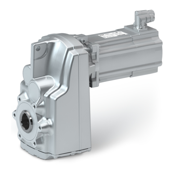
Bevel gearbox / bevel gearbox with three-phase ac motor
Hide thumbs
Also See for g500 Series:
- Mounting instruction (132 pages) ,
- Mounting instructions (57 pages) ,
- Mounting and switch-on instructions (72 pages)

Related Manuals for Lenze g500 Series


Summary of Contents for Lenze g500 Series
- Page 1 g500 G50AB045 ... G50BB320 | 45 Nm ... 20000 Nm Bevel gearbox / Bevel gearbox Mounting Instructions with three−phase AC motor...
- Page 2 Please read these instructions before you start working! Follow the enclosed safety instructions. 0Abb. 0Tab. 0...
-
Page 3: Table Of Contents
............Lenze ¯ MA 12.0014 ¯ 5.1... -
Page 4: Contents
..........Lenze ¯ MA 12.0014 ¯ 5.1... -
Page 5: About This Documentation
Qualified skilled personnel are persons who have the required qualifications to carry out all activities involved in installing, mounting, commissioning, and operating the product. Tip! Information and tools concerning the Lenze products can be found in the download area at www.lenze.com Lenze ¯ MA 12.0014 ¯ 5.1... -
Page 6: Document History
Wildcard Wildcard for options, selection data Terminology used Term In the following text used for Gearboxes Gearboxes of the g500 product family Drive system Drive systems with g500 gearboxes and other Lenze drive components Lenze ¯ MA 12.0014 ¯ 5.1... -
Page 7: Notes Used
Reference to a possible danger that may result in property Stop! damage if the corresponding measures are not taken. Application notes Pictograph and signal word Meaning Important note to ensure trouble−free operation Note! Useful tip for easy handling Tip! Reference to another document Lenze ¯ MA 12.0014 ¯ 5.1... -
Page 8: Safety Instructions
... must not be actuated if the drive system shows vibration accelerations > 2g (20m/s ... must not be actuated in the resonance range of a system or the Lenze drive system. ¯ All specifications of the corresponding enclosed documentation must be observed. - Page 9 ¯ check that all component parts with a loose fastening are secured or removed; ¯ tighten all transport aids (eye bolts or support plates). Use an appropriate means of transport and lifting equipment! (¶ 19) Lenze ¯ MA 12.0014 ¯ 5.1...
- Page 10 Corrosion protection Lenze offers paints with different resistance characteristics for drive systems. Since the resistance may be reduced when the paint coat is damaged, defects in paint work (e.g. through transport or assembly) must be removed professionally to reach the required corrosion resistance.
- Page 11 ¯ We recommend loading the gearbox with a maximum of 50 % of the rated output torque if it is outside the specified temperature range during commissioning. Disposal Sort individual parts according to their properties. Dispose of them as specified by the current national regulations. Lenze ¯ MA 12.0014 ¯ 5.1...
-
Page 12: Application As Directed
... must only be operated under the operating conditions and power limits specified in this documentation. – ... comply with the protection requirements of the EU Low−Voltage Directive. Any other use shall be deemed inappropriate! Lenze ¯ MA 12.0014 ¯ 5.1... -
Page 13: Foreseeable Misuse
Foreseeable misuse Impermissible applications: ¯ In a potentially explosive atmosphere – Exception: special ATEX design ¯ In aggressive environments (acids, gases, vapours, dusts, or oils). ¯ Under water or in liquids ¯ Under radiation Lenze ¯ MA 12.0014 ¯ 5.1... -
Page 14: Residual Hazards
Never disconnect plug when energised! Otherwise, the plug can be destroyed. – Switch off power supply and inhibit controller prior to disconnecting the plug. Fire protection ¯ Fire hazard – Prevent contact with flammable substances. Lenze ¯ MA 12.0014 ¯ 5.1... -
Page 15: Product Description
Product description Important notes Product description Important notes ¯ The most important technical data is given on the nameplate. ¯ The product catalogues contain further technical data. Lenze ¯ MA 12.0014 ¯ 5.1... -
Page 16: Identification
16.6 10.2 10.3 Gearbox with motor adapter 10.2 10.3 20.1 Three−phase AC motor for motor adapter 14.2 14.1 16.1 16.2 r/min 14.3 16.3 16.4 16.4 16.5 20.1 16.5 cos j 10.2 10.3 16.6 16.7 Lenze ¯ MA 12.0014 ¯ 5.1... -
Page 17: Contents
C86 = motor code for inverter parameterisation (code 0086) Efficiency class CC number Department of Energy (optional) Permissible ambient temperature (e.g. Ta £ 40°C) Weight Encoder data 33.1 Encoder type 33.2 Encoder voltage Internal key: QR code Lenze ¯ MA 12.0014 ¯ 5.1... -
Page 18: Gearbox Code
NEMA adapter with a plug−in hollow shaft with a keyway IEC adapter with a plug−in hollow shaft with a keyway IEC adapter with a jaw coupling IEC adapter with a jaw coupling with a keyway Lenze ¯ MA 12.0014 ¯ 5.1... -
Page 19: Mechanical Installation
The gearboxes of sizes G50BB280 ... G50BB320 can be lifted at the ear that is cast on to the housing. G50A0B45 ... G50BB124 G50BB145 ... G50BB243 G50BB280 ... G50BB320 Fig. 1 Positioning of the eye bolt for transporting the complete drive system Lenze ¯ MA 12.0014 ¯ 5.1... - Page 20 Use additional appropriate lifting aids, if required, to achieve a direction of loading which is as vertical as possible (highest payload). Secure lifting aids against shifting! Stop! Observe load carrying capacity! Standing beneath floating loads is prohibited! Lenze ¯ MA 12.0014 ¯ 5.1...
-
Page 21: Preparation
¯ In some cases, due to lack of space, stud bolts with nuts must be used instead of head screws. In these cases, contact Lenze, if necessary. Tighten all screw connections with the torques given and lock them with standard... -
Page 22: General Information About The Assembly Of Drive Systems
10.9 with correspondingly high tightening torques. – Secure screwed connections with medium strength using screw locking adhesive. Lenze ¯ MA 12.0014 ¯ 5.1... -
Page 23: Gearboxes With Breathers
Gearboxes that are delivered with a ventilation unit are provided with a label. Remove the transport locking device on the vent valve before initial commissioning. GT−GNG−13285760.iso/dms Note! Loosely enclosed vent valves must be mounted in accordance with the mounting position, (¶ 50). Lenze ¯ MA 12.0014 ¯ 5.1... -
Page 24: Gearbox With Compensation Container (Preferably For Mounting Pos. "C")
¯ If the pipe shows any signs of damage, replace it. Note! With unfavourable combinations of a small ratio and a high input speed, the use of a compensation reservoir may also be advisable in other mounting positions. Lenze ¯ MA 12.0014 ¯ 5.1... -
Page 25: Mounting The Gearboxes
Gearbox with output flange ¯ Especially with regard to applications with an alternating load, Lenze recommends...: – the use of anaerobic adhesive between the gearbox flange and mounting area in order to increase the friction fit;... -
Page 26: Maximum Permissible Load At The Motor Adapter
B450 B600 G50BB111 G50BB124 G50BB145 G50BB160 NEMA [mm] Maximum permissible force F M Tab xA/2B − 1000 1500 −−−−− 1000 1500 − −−−−− −−−−− −−−−− 1500 −−−−− −−−−− −−−−− −−−−− −−−−− −−−−− −−−−− −−−−− Lenze ¯ MA 12.0014 ¯ 5.1... - Page 27 M Tab 1540 − − 2220 2210 − − 2500 2490 2450 4490 4480 4420 5230 5230 5230 4500 4500 4500 − 3720 3720 3720 6980 7100 7100 6200 6880 6880 − − 11400 11400 Lenze ¯ MA 12.0014 ¯ 5.1...
-
Page 28: Mounting Of Motors To Gearboxes With An Adapter And A Flexible Coupling
With higher degrees of protection or when there is a risk of dirt or humidity entering, additionally seal the contact surfaces with a suitable sealant. B14/ FT B5/FF g500−H_X−002.iso Spider / gear rim Locking screw Coupling hub Keyway Lenze ¯ MA 12.0014 ¯ 5.1... - Page 29 Tab. 3 Attachment of motors to gearboxes with adapter * Use original featherkey of the motor 1) Featherkey for standard hub and clamping hub 2) Measured from the seating face of the motor flange Lenze ¯ MA 12.0014 ¯ 5.1...
-
Page 30: Coupling Hubs
For this purpose, only use mineral oil−based lubricants without additives, silicone−based lubricants, or vaseline. 5. Align claws of the motor−side coupling hub with its counterpart. 6. Slowly push on motor, and bolt on to the gearbox flange. Lenze ¯ MA 12.0014 ¯ 5.1... - Page 31 For this purpose, only use mineral oil−based lubricants without additives, silicone−based lubricants, or vaseline. 6. Align claws of the motor−side coupling hub with its counterpart. 7. Slowly push on motor, and bolt on to the gearbox flange. Lenze ¯ MA 12.0014 ¯ 5.1...
- Page 32 3. Tighten the screws in the forcing threads crosswise and step−by−step so that the clamping ring is loosened. 4. Clean and grease all contact surfaces including threads and head of the clamping screws before reassembly. Lenze ¯ MA 12.0014 ¯ 5.1...
-
Page 33: Mounting Of Motors To Gearboxes With A Short Adapter With A Plug−In Hollow Shaft With A Keyway (Drive−End Version B Or H)
By no means join the parts by hammer strokes! 6. Screw the motor and gearbox flange together, securing the fixing screws using medium−strength screw locking adhesive. Lenze ¯ MA 12.0014 ¯ 5.1... -
Page 34: Attachment Of Gearboxes With Hollow Shafts And Keyway
Take up forces only via the hollow shaft, and not via gearbox housing. 5. Secure the gearbox axially: – The hollow shaft has snap ring grooves for axial securing. Parts used to fix the shaft are not included in the scope of supply. K12.0611 Lenze ¯ MA 12.0014 ¯ 5.1... - Page 35 Mechanical installation Preparation Attachment of gearboxes with hollow shafts and keyway Auxiliary tool (recommended dimensions) Æ Tab. 4 Dimensions in [mm] 6. Cover rotating screw heads, interfering edges, slots or similar items safe against contact. Lenze ¯ MA 12.0014 ¯ 5.1...
- Page 36 −−− 59.8 −−− 64.1 19.8 −−− 69.8 −−− 74.1 21.8 −−− 79.8 −−− 85.1 24.8 −−− 89.8 27.8 −−− 99.8 31.8 −−− 119.8 Tab. 5 Dimensions in mm Auxiliary tool for gearbox size G50BB124 Lenze ¯ MA 12.0014 ¯ 5.1...
- Page 37 Gearbox l max. Code Type G50AB045 g500−B45 G50BB111 g500−B110 G50BB124 g500−B240 G50BB145 g500−B450 G50BB160 g500−B600 G50BB182 g500−B820 G50BB215 g500−B1500 G50BB227 g500−B2700 G50BB243 g500−B4300 G50BB280 g500−B8000 G50BB313 g500−B13000 G50BB320 g500−B20000 Tab. 6 Dimensions in mm Lenze ¯ MA 12.0014 ¯ 5.1...
-
Page 38: Mounting The Shrink Disc With A Rotating Cover
4. Slightly loosen clamping screws (2) one after the other, do not unscrew! 5. Push drive onto machine shaft. Lenze ¯ MA 12.0014 ¯ 5.1... - Page 39 Torque [ Nm ] Hollow shaft bore [mm] Clamping screw thread Width across flats [mm] Torque [ Nm ] Tab. 7 Tightening torque for the clamping screws Width across flats of the shrink disc clamping screws Lenze ¯ MA 12.0014 ¯ 5.1...
- Page 40 ¯ the connection is spinning due to overload or a too low friction factor and fretting corrosion has occurred, ¯ the shrink disc has been tightened too much leading to a plastic deformation of components, ¯ the components are corroded. Lenze ¯ MA 12.0014 ¯ 5.1...
-
Page 41: Mounting The Fixed Cover
1. Screw reducing bushes (3) into the flange so that they are flush using a screwdriver. 2. Fasten the protective cap (1) over the reducing bushes (3) on the flange using cheese head screws (2). Lenze ¯ MA 12.0014 ¯ 5.1... -
Page 42: Mounting The Hoseproof Hollow Shaft Cover
Protection cover Seal Cheese head screw 1. Place seal (4) between the flange and the protection cover (1). 2. Fasten the protection cover (1) on the housing flange using cheese head screws (2). Lenze ¯ MA 12.0014 ¯ 5.1... -
Page 43: Torque Plate Assembly
In the case of a knee lever design, transfer the force at right angles to the torque plate, if possible (90°±20°). Mounting 1. Clean the contact surfaces between the housing and torque plate. 2. Tighten the screws according to the torque specified, (¶ 21) Lenze ¯ MA 12.0014 ¯ 5.1... -
Page 44: Electrical Installation
To correctly connect the motor options, e. g. brakes or feedback systems, please observe: ¯ the notes in the corresponding terminal box ¯ the notes in the corresponding operating instructions ¯ the technical data on the corresponding motor nameplate. Lenze ¯ MA 12.0014 ¯ 5.1... -
Page 45: Commissioning And Operation
Has the transport locking device been removed? Stop! At drive speeds below 200 rpm the amount of lubricant may need to be increased. Consultation with Lenze is required. Initial commissioning In order to ensure trouble−free operation, carry out checks during initial commissioning. -
Page 46: During Operation
¯ In the event of faults: – shut down the drive, – check the troubleshooting table. If the fault cannot be remedied, please contact the Lenze customer service. Lenze ¯ MA 12.0014 ¯ 5.1... -
Page 47: Maintenance
– The lubricant change depends on the lubricant temperature, see Fig. 12. 1. Measure the lubricant temperature at the drain plug, 2. Add 10 °C, 3. Read the changing interval from the diagram. Lenze ¯ MA 12.0014 ¯ 5.1... - Page 48 Replace roller bearing When an oil change is carried out, the roller grease filling bearing grease filling should also be replaced ^ 63 Lenze ¯ MA 12.0014 ¯ 5.1...
-
Page 49: Maintenance Operations
Maintenance operations Maintenance operations Gearboxes and geared motors are ready to use on delivery and filled by Lenze with the lubricant type and lubricant quantity indicated on the nameplate. The first filling corresponds to the mounting position and design indicated on the nameplate. -
Page 50: Position Of The Lubricant Monitoring Elements
Maintenance Maintenance operations Position of the lubricant monitoring elements 7.3.1 Position of the lubricant monitoring elements G50BB124 Mounting position A Mounting position B Mounting position C Filling Drain Breathing Control Lenze ¯ MA 12.0014 ¯ 5.1... - Page 51 Maintenance Maintenance operations Position of the lubricant monitoring elements Mounting position D Mounting position E Mounting position F Filling Drain Breathing Control The shown oil bores are optional for gearbox size g500−B240! Lenze ¯ MA 12.0014 ¯ 5.1...
- Page 52 Maintenance Maintenance operations Position of the lubricant monitoring elements G50BB145 Mounting position A Mounting position B Mounting position C Filling Drain Breathing Control Lenze ¯ MA 12.0014 ¯ 5.1...
- Page 53 Maintenance Maintenance operations Position of the lubricant monitoring elements Mounting position D Mounting position E Mounting position F Filling Drain Breathing Control Lenze ¯ MA 12.0014 ¯ 5.1...
- Page 54 Maintenance Maintenance operations Position of the lubricant monitoring elements G50BB160 ... G50BB243 Mounting position A Mounting position B Mounting position C G50BB215 G50BB227 G50BB160 G50BB182 G50BB243 Filler Drain Breather element Check Lenze ¯ MA 12.0014 ¯ 5.1...
- Page 55 Maintenance operations Position of the lubricant monitoring elements Mounting position D Mounting position E Mounting position F G50BB227 G50BB243 G50BB160 G50BB215 G50BB185 G50BB215 G50BB215 G50BB160 G50BB182 G50BB227 G50BB243 G50BB215 Filler Drain Breather element Check Lenze ¯ MA 12.0014 ¯ 5.1...
- Page 56 Maintenance Maintenance operations Position of the lubricant monitoring elements G50BB280 ... G50BB320 Mounting position A Mounting position B Mounting position C Filling Drain Breathing Control Borehole on both sides Lenze ¯ MA 12.0014 ¯ 5.1...
- Page 57 Maintenance Maintenance operations Position of the lubricant monitoring elements Mounting position D Mounting position E Mounting position F Filling Drain Breathing Control Borehole on both sides Lenze ¯ MA 12.0014 ¯ 5.1...
-
Page 58: Table Of Lubricants
Lubricants with a USDA H1 approval are approved for the use in the food industry. Note! In case of ambient temperatures < −20°C or > +40°C, please contact Lenze! Observe increased starting torques at low temperatures! Lenze ¯ MA 12.0014 ¯ 5.1... -
Page 59: Checking The Oil Level
Note! Check the oil level in cold condition! Check the oil level by means of the displayed dipsticks. Manufacture them according to the mounting position. Form template: dipsticks for G50BB124 A, 3-stage A, 2-stage Lenze ¯ MA 12.0014 ¯ 5.1... - Page 60 Maintenance Maintenance operations Checking the oil level Form template: dipsticks for G50BB145 Lenze ¯ MA 12.0014 ¯ 5.1...
- Page 61 Bleeder screw/oil filler plug Oil−level bore d2 [mm] Filling height x [mm] Tightening torque [Nm] M10 x 1 M12 x 1.5 M16 x 1.5 M20 x 1.5 G 1/8" G 1/4" G 3/8" G 3/4" Lenze ¯ MA 12.0014 ¯ 5.1...
-
Page 62: Changing The Oil
Then a residual amount of oil remains in the gearbox. If a change−over to a food−compatible gearbox oil is to be effected, the gearbox must be rinsed thoroughly with the food−compatible gearbox oil. Lenze ¯ MA 12.0014 ¯ 5.1... -
Page 63: Lubricate Roller Bearings
Maintenance Maintenance operations Lubricate roller bearings 7.3.5 Lubricate roller bearings The roller bearings on motors and gearboxes from Lenze are filled with the greases listed below: Ambient temperature Manufacturer Type Gearbox roller bearing −30 °C ... +50 °C Fuchs Renolit H 443 −30 °C ... -
Page 64: Drain Condensation
If the condensation drain holes are not sealed again, the IP enclosure of the motor will be reduced. For horinzontal motor shafts to IP23 and for vertical motor shafts to IP20. Fig. 14 Motor with condensation drain holes Condensation drain holes Lenze ¯ MA 12.0014 ¯ 5.1... -
Page 65: Repair
Maintenance Repair Drain condensation Repair ¯ We recommend having all repairs carried out by the Lenze Service department. Lenze ¯ MA 12.0014 ¯ 5.1... -
Page 66: Troubleshooting And Fault Elimination
If any malfunctions should occur during operation of the drive system, please check the possible causes using the following table. If the fault cannot be eliminated by one of the listed measures, please contact the Lenze Service. Fault Possible cause... - Page 67 Notes Lenze ¯ MA 12.0014 ¯ 5.1...
- Page 68 © 09/2018 | MA 12.0014 | .Xqô | 5.1 | TD29 Lenze Drives GmbH Postfach 10 13 52, 31763 Hameln Breslauer Straße 3, 32699 Extertal GERMANY HR Lemgo B 6478 Ü +49 5154 82−0 Ø +49 5154 82−2800 Ù lenze@lenze.com Ú...
Need help?
Do you have a question about the g500 Series and is the answer not in the manual?
Questions and answers
Hi I have 10 Lenze motor gearboxes, when do I need to change the oil ? G50BB243MSAR3C00 Thank you.