Lenze g500 Series Mounting Instructions
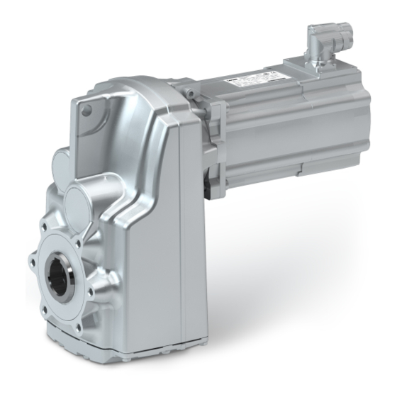
Shaft-mounted helical gearboxes / shaft-mounted helical gearboxes with servo motor
Hide thumbs
Also See for g500 Series:
- Mounting instruction (132 pages) ,
- Mounting instructions (68 pages) ,
- Mounting and switch-on instructions (72 pages)

Subscribe to Our Youtube Channel
Related Manuals for Lenze g500 Series


Summary of Contents for Lenze g500 Series
- Page 1 g500 S130 ... S660 | 130 Nm ... 660 Nm Shaft−mounted helical gearboxes / shaft−mounted Mounting Instructions helical gearboxes with servo motor...
- Page 2 Please read these instructions before you start working! Follow the enclosed safety instructions. 0Abb. 0Tab. 0...
-
Page 3: Table Of Contents
............Lenze ¯ MA 12.0018 ¯ 2.0... - Page 4 ..........Lenze ¯ MA 12.0018 ¯ 2.0...
-
Page 5: About This Documentation
Qualified skilled personnel are persons who have the required qualifications to carry out all activities involved in installing, mounting, commissioning, and operating the product. Tip! Information and tools concerning the Lenze products can be found in the download area at www.lenze.com Document history... -
Page 6: Terminology Used
In the following text used for Gearboxes Gearboxes of the g500 product family Drive system Drive systems with g500 gearboxes and other Lenze drive components Notes used The following pictographs and signal words are used in this documentation to indicate... -
Page 7: Safety Instructions
This is vital for safe and trouble−free operation and for achieving the specified product features. ¯ Only qualified skilled personnel are permitted to work with or on Lenze drive and automation components. According to IEC 60364 or CENELEC HD 384, these are persons ... - Page 8 Corrosion protection Lenze offers paints with different resistance characteristics for drive systems. Since the resistance may be reduced when the paint coat is damaged, defects in paint work (e.g.
-
Page 9: Application As Directed
... in explosion−protected areas – ... in aggressive environments (acid, gas, vapour, dust, oil) – ... in water – ... in radiation environments Note! Increased surface and corrosion protection can be achieved by using adapted coating systems. Lenze ¯ MA 12.0018 ¯ 2.0... -
Page 10: Residual Hazards
¯ Design with plug: – Never disconnect plug when energised! Otherwise, the plug can be destroyed. – Switch off power supply and inhibit controller prior to disconnecting the plug. Lenze ¯ MA 12.0018 ¯ 2.0... -
Page 11: Disposal
Safety instructions Disposal Fire protection ¯ Fire hazard – Prevent contact with flammable substances. Disposal Sort individual parts according to their properties. Dispose of them as specified by the current national regulations. Lenze ¯ MA 12.0018 ¯ 2.0... -
Page 12: Product Description
Mounting position (A−F) and position of system modules (1−6) Hollow shaft: Without foot: Solid shaft: Foot: 3, 4, 5 Hollow shaft with shrink disc: 1, 6 Connector / terminal box: 2, 3, 4, 5 Flange: Lenze ¯ MA 12.0018 ¯ 2.0... -
Page 13: Nameplate
Product description Nameplate 3.2.1 Nameplate Gearbox 10.2 10.3 10.1 20.1 Asynchronous and synchronous servo motors 16.6 5.10 14.2 14.3 14.1 10.2 10.3 Lenze ¯ MA 12.0018 ¯ 2.0... - Page 14 Year of manufacture / week of manufacture Customer data 20.1 Additional customer data UL category (e.g. inverter duty motor) C86 = motor code for inverter parameterisation (code 0086) Permissible ambient temperature (e.g. Ta £ 40°C) Load capacity (specified if c<1.0) Lenze ¯ MA 12.0018 ¯ 2.0...
-
Page 15: Transport Weights
< 15 < 20 < 25 < 45 G50BS140 g500−S400 < 20 < 25 < 30 < 45 G50BS166 g500−S660 < 25 < 30 < 35 < 50 Tab. 2 Weights in kg Lenze ¯ MA 12.0018 ¯ 2.0... -
Page 16: Mechanical Installation
Stop! Observe load carrying capacity! Standing beneath floating loads is prohibited! g500−S130 ... S660 Fig. 1 Ear of the complete drive system Lenze ¯ MA 12.0018 ¯ 2.0... -
Page 17: Preparation
DIN 42955 R (reference values for smooth running < 0.025 mm; axial runout and concentricity < 0.05 mm). Lenze ¯ MA 12.0018 ¯ 2.0... - Page 18 ¯ The drive system must have cooled down. ¯ The motor must be deenergised. Note! Lenze recommends the use of smooth motor shafts without slots! 1. Check: ¯ If the drill depth in the hollow drive shaft is sufficient for the motor shaft.
- Page 19 Removing the plug from the bell housing Gearbox Plug Bell housing 3. Align the slots of the gearbox drive hollow shaft and the clamping ring to each other and to the mounting hole (Fig. 5). Lenze ¯ MA 12.0018 ¯ 2.0...
- Page 20 Mounting of motor and gearbox Gearbox Wrench Motor Stop! If the motor shaft is provided with a keyway, align the motor shaft in such a way that the keyway is located opposite to the terminal screw. Lenze ¯ MA 12.0018 ¯ 2.0...
- Page 21 Mounting the gearboxes Note! Lenze recommends the use of smooth motor shafts without slots! 5. Position the motor shaft vertically and centrically to the hollow drive shaft and insert it carefully into the hollow drive shaft. Exert only little force in order to prevent damage to the ball bearing in the bell housing and the motor.
-
Page 22: Mounting Of Motors On Gearboxes With Mounting Flange And Flexible Coupling (Drive−End Version N)
B8 x 7 x 18 B6 x 6 x 18 Tab. 3 Attachment of motors to gearboxes with mounting flange * Use original key for the motor Key for standard hub and clamping hub Lenze ¯ MA 12.0018 ¯ 2.0... - Page 23 5. Lay spider in the coupling claw on the gearbox side. 6. Align claws of the motor−side coupling hub with its counterpart. 7. Slowly push on motor, and bolt on to the gearbox flange. Lenze ¯ MA 12.0018 ¯ 2.0...
-
Page 24: Attachment Of Gearboxes With Hollow Shafts And Keyway
Take up forces only via the hollow shaft, and not via gearbox housing. 2. Secure the gearbox axially: – The hollow shaft has snap ring grooves for axial securing. Parts used to fix the shaft are not included in the scope of supply. Lenze ¯ MA 12.0018 ¯ 2.0... - Page 25 2. Remove/extract the gearbox from the motor shaft using an appropriate auxiliary tool (Fig. 10). K12.0611 Fig. 10 Disassembly of gearboxes with hollow shaft, with auxiliary tool Auxiliary tool (recommended dimensions) Æ Tab. 5 Dimensions in mm Lenze ¯ MA 12.0018 ¯ 2.0...
-
Page 26: Mounting The Shrink Disc With A Rotating Cover
Never tighten clamping screws before the machine shaft is pushed in. Otherwise the hollow shaft may be deformed plastically. Protect the shrink disc against contact while in operation by appropriate measures (e.g. cover). Degrease hollow shaft bore and machine shaft! Lenze ¯ MA 12.0018 ¯ 2.0... - Page 27 6. Slightly tighten clamping screws manually. 7. Tighten clamping screws (2) one after the other (see Fig. 12) in several passes, with rising torque, evenly until the indicated screw−tightening torque (see Tab. 7 ) is reached at all screws. Lenze ¯ MA 12.0018 ¯ 2.0...
- Page 28 8. Push protective cap (1, Fig. 11) onto the shrink disc. Tip! For finding out the cause of non−reached torques of the shrink disc connection, please go through the troubleshooting list in chapter 7. Lenze ¯ MA 12.0018 ¯ 2.0...
- Page 29 ¯ the connection is spinning due to overload or a too low friction factor and fretting corrosion has occurred, ¯ the shrink disc has been tightened too much leading to a plastic deformation of components, ¯ the components are corroded. Lenze ¯ MA 12.0018 ¯ 2.0...
-
Page 30: Mounting The Fixed Cover
120°. 2. Fit seal (4) between flange and protective cap (1). 3. Fasten the protective cap (1) over the reducing bushes (3) on the flange using three cheese head screws (2). Lenze ¯ MA 12.0018 ¯ 2.0... -
Page 31: Foot Mounting
No ventilation measures are required for the gearboxes g500−S130 and g500−S220. Gearboxes which are delivered with a ventilation unit are equipped with a label on the gearbox. Remove the transport locking device on the vent valve before the first commissioning. GT−GNG−13285760.iso/dms Lenze ¯ MA 12.0018 ¯ 2.0... -
Page 32: Electrical Connection
The notes for the electrical connection can be found in... ¯ in the terminal box (in the case of motors with terminal box). ¯ in the connection plan (in the case of motors with plugs). Lenze ¯ MA 12.0018 ¯ 2.0... -
Page 33: Commissioning And Operation
¯ For gearboxes with breathing elements: – Has the transport locking device been removed? Stop! At drive speeds below 200 rpm the amount of lubricant may need to be increased. Consultation with Lenze is required. Lenze ¯ MA 12.0018 ¯ 2.0... -
Page 34: During Operation
¯ In the event of faults: – shut down the drive, – check the troubleshooting table. If the fault cannot be remedied, please contact the Lenze customer service. Lenze ¯ MA 12.0018 ¯ 2.0... -
Page 35: Maintenance
Maintenance operations Gearboxes and geared motors are ready to use on delivery and filled by Lenze with the lubricant type and lubricant quantity indicated on the nameplate. The first filling corresponds to the mounting position and design indicated on the nameplate. - Page 36 Maintenance Maintenance operations Breather position, oil filling screw and drain plug G50BS140 G50BS113 G50BS122 G50BS113 G50BS122 G50BS140+ G50BS166 G50BS140+ G50BS166 G50BS113 G50BS113 G50BS122 G50BS113 G50BS113 Filler Drain Breather element Check Lenze ¯ MA 12.0018 ¯ 2.0...
- Page 37 Maintenance Maintenance operations Oil−level inspection Check the oil level by means of the displayed dipsticks. Manufacture them according to the mounting position. Form template: dipsticks for G50BS113 A, C, F Lenze ¯ MA 12.0018 ¯ 2.0...
- Page 38 Maintenance Maintenance operations Form template: dipsticks for G50BS122 Lenze ¯ MA 12.0018 ¯ 2.0...
- Page 39 Maintenance Maintenance operations Form template: dipsticks for G50BS140 Lenze ¯ MA 12.0018 ¯ 2.0...
- Page 40 Maintenance Maintenance operations Form template: dipsticks for G50BS166 A, E Lenze ¯ MA 12.0018 ¯ 2.0...
-
Page 41: Repair
5. Fill in lubricant through filler hole (quantities see nameplate). 6. Screw in breathing / oil filler plug. 7. Dispose of waste oil according to the applicable regulations. Repair ¯ We recommend having all repairs carried out by the Lenze customer service. Lenze ¯ MA 12.0018 ¯ 2.0... -
Page 42: Troubleshooting And Fault Elimination
If any malfunctions should occur during operation of the drive system, please check the possible causes using the following table. If the fault cannot be eliminated by one of the listed measures, please contact the Lenze Service. Fault Possible cause... - Page 43 Notes Lenze ¯ MA 12.0018 ¯ 2.0...
- Page 44 © 04/2017 | MA 12.0018 | .V8i | 2.0 | TD09 Lenze Drives GmbH Postfach 10 13 52, 31763 Hameln Breslauer Straße 3, 32699 Extertal GERMANY HR Lemgo B 6478 Ü +49 5154 82−0 Ø +49 5154 82−2800 Ù lenze@lenze.com Ú...
Need help?
Do you have a question about the g500 Series and is the answer not in the manual?
Questions and answers
how to separate a lenze g50bs122mhcrcoo gearbox from a lenze mcs09h41-rsop2 motor
@Jeff Rodgers
1. Switch Off Power: Ensure the power supply is switched off and the controller is inhibited before starting.
2. Secure the Unit: Make sure the gearbox and motor are stable to prevent falling or toppling.
3. Remove the Plug: Locate and remove the plug from the bell housing.
4. Loosen the Clamping Connection: Align the slots of the gearbox drive hollow shaft and clamping ring with the mounting hole, then loosen the clamping connection.
5. Separate the Motor: Carefully pull the motor away from the gearbox while ensuring no components are damaged.
Follow all safety precautions during the process.
This answer is automatically generated
need help please