
Related Manuals for Lenze G50BH314


Summary of Contents for Lenze G50BH314
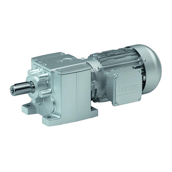
- Page 1 G50AH045 ... G50BH314 | 45 Nm ... 14000 Nm Helical gearboxes / Helical gearboxes with Mounting Instructions three−phase AC motors...
- Page 2 Please read these instructions before you start working! Follow the enclosed safety instructions. 0Abb. 0Tab. 0...
-
Page 3: Table Of Contents
............Lenze ¯ MA 12.0012 ¯ 3.0... - Page 4 ..........Lenze ¯ MA 12.0012 ¯ 3.0...
-
Page 5: About This Documentation
Qualified skilled personnel are persons who have the required qualifications to carry out all activities involved in installing, mounting, commissioning, and operating the product. Tip! Information and tools concerning the Lenze products can be found in the download area at www.lenze.com Document history... -
Page 6: Terminology Used
In the following text used for Gearboxes Gearboxes of the g500 product family Drive system Drive systems with g500 gearboxes and other Lenze drive components Notes used The following pictographs and signal words are used in this documentation to indicate... -
Page 7: Safety Instructions
... must not be actuated if the drive system shows vibration accelerations > 2g (20m/s ... must not be actuated in the resonance range of a system or the Lenze drive system. ¯ All specifications of the corresponding enclosed documentation must be observed. - Page 8 ¯ check that all component parts with a loose fastening are secured or removed; ¯ tighten all transport aids (eye bolts or support plates). Use an appropriate means of transport and lifting equipment! (¶ 17) Lenze ¯ MA 12.0012 ¯ 3.0...
- Page 9 Corrosion protection Lenze offers paints with different resistance characteristics for drive systems. Since the resistance may be reduced when the paint coat is damaged, defects in paint work (e.g. through transport or assembly) must be removed professionally to reach the required corrosion resistance.
- Page 10 ¯ We recommend loading the gearbox with a maximum of 50 % of the rated output torque if it is outside the specified temperature range during commissioning. Disposal Sort individual parts according to their properties. Dispose of them as specified by the current national regulations. Lenze ¯ MA 12.0012 ¯ 3.0...
-
Page 11: Application As Directed
Connections must only be made when the equipment is deenergised and the motor is at standstill. – Installed brakes are no fail−safe brakes. ¯ Dangerous voltages at the power terminals, even if the plug is removed: residual voltage >60 V! Lenze ¯ MA 12.0012 ¯ 3.0... - Page 12 Never disconnect plug when energised! Otherwise, the plug can be destroyed. – Switch off power supply and inhibit controller prior to disconnecting the plug. Fire protection ¯ Fire hazard – Prevent contact with flammable substances. Lenze ¯ MA 12.0012 ¯ 3.0...
-
Page 13: Product Description
20.1 16.7 cos j 16.6 10.2 10.3 Three−phase AC motor with a standard output flange 14.2 14.1 16.1 16.2 14.3 r/min 16.3 16.4 16.4 16.5 20.1 16.5 cos j 10.2 10.3 16.6 16.7 Lenze ¯ MA 12.0012 ¯ 3.0... - Page 14 Partial load efficiencies for 50Hz operation at a rated power of 50% and 75% CC number Department of Energy (optional) Permissible ambient temperature (e.g. Ta £ 40°C) Weight Encoder data 33.1 Encoder type 33.2 Encoder voltage Internal key: QR code Lenze ¯ MA 12.0012 ¯ 3.0...
-
Page 15: Gearbox Code
Foot mounting + centering Foot mounting Centering Flange mounting Without flange Flange with through holes Reinforced design Number of stages 2−stage 3−stage Motor mounting Integrated IEC adapter NEMA adapter Servo adapter Lenze drive size Lenze ¯ MA 12.0012 ¯ 3.0... -
Page 16: Transport Weights
<460 G50BH250 g500−H5000 <240 <260 <260 <320 < 400 <520 <640 <780 G50BH280 g500−H8000 <360 <360 <420 <500 <620 <760 <880 G50BH314 g500−H14000 <520 <580 <660 <800 <920 <1050 Tab. 1 Weights in kg Lenze ¯ MA 12.0012 ¯ 3.0... -
Page 17: Mechanical Installation
The eye bolt is not included in the scope of supply! G50AH045...G50BH114 G50BH121...G50BH230 G50BH250...G50BH314 Fig. 1 Position of the eye bolt for transporting the complete drive system Lenze ¯ MA 12.0012 ¯ 3.0... - Page 18 Use additional appropriate lifting aids, if required, to achieve a direction of loading which is as vertical as possible (highest payload). Secure lifting aids against shifting! Stop! Observe load carrying capacity! Standing beneath floating loads is prohibited! Lenze ¯ MA 12.0012 ¯ 3.0...
-
Page 19: Preparation
¯ In some cases, due to lack of space, stud bolts with nuts must be used instead of head screws. In these cases, contact Lenze, if necessary. Tighten all screw connections with the torques given and lock them with standard... -
Page 20: General Information About The Assembly Of Drive Systems
10.9 with correspondingly high tightening torques. – Secure screwed connections using screw locking adhesive. Lenze ¯ MA 12.0012 ¯ 3.0... -
Page 21: Gearboxes With Breathers
Note! With unfavourable combinations of a small ratio and a high input speed, the use of a compensation reservoir may also be advisable in other mounting positions. Lenze ¯ MA 12.0012 ¯ 3.0... -
Page 22: Mounting The Gearboxes
Gearbox with output flange ¯ Especially with regard to applications with an alternating load, Lenze recommends...: – the use of anaerobic adhesive between the gearbox flange and mounting area in order to increase the friction fit;... - Page 23 [−] [mm] Maximum permissible force F M Tab xA/2B −−−−− −−−−− −−−−− −−−−− −−−−− 1500 1500 1500 1500 1500 1500 1500 1500 1500 1500 1500 1500 1500 1700 1700 1700 −−−−− −−−−− 2600 3500 Lenze ¯ MA 12.0012 ¯ 3.0...
-
Page 24: Drive−End Version N
Tab. 4 Attachment of motors to gearboxes with mounting flanges * Use original featherkey of the motor 1) Featherkey for standard hub and clamping hub 2) Measured from the seating face of the motor flange Lenze ¯ MA 12.0012 ¯ 3.0... -
Page 25: Coupling Hubs
6. Slowly push on motor, and bolt on to the gearbox flange. Mounting the clamping ring hub Fig. 3 Coupling Clamping ring hub Clamping ring Clamping screws (DIN912) Note! The motor shaft must be designed with fit k6. Lenze ¯ MA 12.0012 ¯ 3.0... - Page 26 3. Tighten the screws in the forcing threads crosswise and step−by−step so that the clamping ring is loosened. 4. Clean and grease all contact surfaces including threads and head of the clamping screws before reassembly. Lenze ¯ MA 12.0012 ¯ 3.0...
-
Page 27: Electrical Installation
To correctly connect the motor options, e. g. brakes or feedback systems, please observe: ¯ the notes in the corresponding terminal box ¯ the notes in the corresponding operating instructions ¯ the technical data on the corresponding motor nameplate. Lenze ¯ MA 12.0012 ¯ 3.0... -
Page 28: Commissioning And Operation
Has the transport locking device been removed? Stop! At input speeds below 200 rpm the amount of lubricant may need to be increased. Consultation with Lenze is required. Initial commissioning In order to ensure trouble−free operation, carry out checks during initial commissioning. -
Page 29: During Operation
¯ In the event of faults: – shut down the drive, – check the troubleshooting table. If the fault cannot be remedied, please contact the Lenze customer service. Lenze ¯ MA 12.0012 ¯ 3.0... -
Page 30: Maintenance
– The service life depends on the operating conditions. – Replace seals in case of leakage to avoid consequential damage. Stop! For drive systems: Also observe the maintenance intervals for the other drive components! Lenze ¯ MA 12.0012 ¯ 3.0... - Page 31 Replace roller bearing When an oil change is carried out, the roller grease filling bearing grease filling should also be replaced ^ 43 Lenze ¯ MA 12.0012 ¯ 3.0...
-
Page 32: Maintenance Operations
Position of the lubricant monitoring elements Maintenance operations Gearboxes and geared motors are ready to use on delivery and filled by Lenze with the lubricant type and lubricant quantity indicated on the nameplate. The first filling corresponds to the mounting position and design indicated on the nameplate. - Page 33 Maintenance Maintenance operations Position of the lubricant monitoring elements Mounting position D Mounting position E Mounting position F G50BH121 G50BH132 G50BH145 Filling Drain Breathing Control Lenze ¯ MA 12.0012 ¯ 3.0...
- Page 34 Maintenance Maintenance operations Position of the lubricant monitoring elements G50BH160 ... G50BH230 Mounting position A Mounting position B Mounting position C Filling Drain Breathing Control Lenze ¯ MA 12.0012 ¯ 3.0...
- Page 35 Maintenance Maintenance operations Position of the lubricant monitoring elements Mounting position D Mounting position E Mounting position F Filling Drain Breathing Control Lenze ¯ MA 12.0012 ¯ 3.0...
- Page 36 Maintenance Maintenance operations Position of the lubricant monitoring elements G50BH250 ... G50BH314 Mounting position A Mounting position B Mounting position C Filling Drain Breathing Control Lenze ¯ MA 12.0012 ¯ 3.0...
- Page 37 Maintenance Maintenance operations Position of the lubricant monitoring elements Mounting position D Mounting position E Mounting position F Filling Drain 2−stage Breathing Control 3−stage Lenze ¯ MA 12.0012 ¯ 3.0...
-
Page 38: Table Of Lubricants
Checking the oil level Note! Check the oil level in cold condition! Geared motors G50BH121 ... G50BH145 Check the oil level by means of the displayed dipsticks. Manufacture them according to the mounting position. Lenze ¯ MA 12.0012 ¯ 3.0... - Page 39 Maintenance Maintenance operations Form template: dipsticks for G50BH121 Lenze ¯ MA 12.0012 ¯ 3.0...
- Page 40 Maintenance Maintenance operations Form template: dipsticks for G50BH132 Lenze ¯ MA 12.0012 ¯ 3.0...
- Page 41 Maintenance Maintenance operations Form template: dipsticks for G50BH145 Lenze ¯ MA 12.0012 ¯ 3.0...
-
Page 42: Changing The Oil
Maintenance Maintenance operations Changing the oil Geared motors G50BH160 ... G50BH314 1. Switch the drive to a deenergised state. 2. Remove oil control plug (¶ 34). 3. Check oil level using a tool. If necessary, refill oil. At the maximum, the oil level must be below the threaded hole by the dimension x. -
Page 43: Lubricate Roller Bearings
Maintenance Maintenance operations Lubricate roller bearings 7.3.5 Lubricate roller bearings The roller bearings on motors and gearboxes from Lenze are filled with the greases listed below: Ambient temperature Manufacturer Type Gearbox roller bearing −30 °C ... +50 °C Fuchs Renolit H 443 −30 °C ... -
Page 44: Drain Condensation
For horinzontal motor shafts to IP23 and for vertical motor shafts to IP20. Fig. 7 Motor with condensation drain holes Condensation drain holes Repair ¯ We recommend having all repairs carried out by the Lenze Service department. Lenze ¯ MA 12.0012 ¯ 3.0... -
Page 45: Troubleshooting And Fault Elimination
If any malfunctions should occur during operation of the drive system, please check the possible causes using the following table. If the fault cannot be eliminated by one of the listed measures, please contact the Lenze Service. Fault Possible cause... - Page 46 Notes Lenze ¯ MA 12.0012 ¯ 3.0...
- Page 47 Notes Lenze ¯ MA 12.0012 ¯ 3.0...
- Page 48 © 05/2017 | MA 12.0012 | .VYJ | 3.0 | TD09 Lenze Drives GmbH Postfach 10 13 52, 31763 Hameln Breslauer Straße 3, 32699 Extertal GERMANY HR Lemgo B 6478 Ü +49 5154 82−0 Ø +49 5154 82−2800 Ù lenze@lenze.com Ú...
Need help?
Do you have a question about the G50BH314 and is the answer not in the manual?
Questions and answers