Lenze g500 Series Mounting Instructions
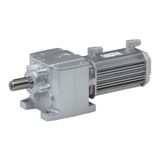
Helical gearboxes/with motor
Hide thumbs
Also See for g500 Series:
- Mounting instruction (132 pages) ,
- Mounting instructions (68 pages) ,
- Mounting and switch-on instructions (72 pages)

Subscribe to Our Youtube Channel
Related Manuals for Lenze g500 Series


Summary of Contents for Lenze g500 Series
- Page 1 g500 G50AH045 ... G50BH314 g500-H450 ... g500-H14000 45 Nm ... 14000 Nm Helical gearboxes Mounting Instructions Helical gearboxes with motor ...
- Page 2 Please read these instructions before you start working! Follow the enclosed safety instructions. 0Abb. 0Tab. 0...
-
Page 3: Table Of Contents
............Lenze ¯ MA 12.0012 ¯ 4.0... - Page 4 ..........Lenze ¯ MA 12.0012 ¯ 4.0...
-
Page 5: About This Documentation
Qualified skilled personnel are persons who have the required qualifications to carry out all activities involved in installing, mounting, commissioning, and operating the product. Tip! Information and tools concerning the Lenze products can be found in the download area at www.lenze.com Document history... -
Page 6: Conventions Used
Wildcard Wildcard for options, selection data Terminology used Term In the following text used for Gearboxes Gearboxes of the g500 product family Drive system Drive systems with g500 gearboxes and other Lenze drive components Lenze ¯ MA 12.0012 ¯ 4.0... -
Page 7: Notes Used
Reference to a possible danger that may result in property Stop! damage if the corresponding measures are not taken. Application notes Pictograph and signal word Meaning Important note to ensure trouble−free operation Note! Useful tip for easy handling Tip! Reference to another document Lenze ¯ MA 12.0012 ¯ 4.0... -
Page 8: Safety Instructions
... must not be actuated if the drive system shows vibration accelerations > 2g (20m/s ... must not be actuated in the resonance range of a system or the Lenze drive system. ¯ All specifications of the corresponding enclosed documentation must be observed. - Page 9 ¯ check that all component parts with a loose fastening are secured or removed; ¯ tighten all transport aids (eye bolts or support plates). Use an appropriate means of transport and lifting equipment! (¶ 19) Lenze ¯ MA 12.0012 ¯ 4.0...
- Page 10 Corrosion protection Lenze offers paints with different resistance characteristics for drive systems. Since the resistance may be reduced when the paint coat is damaged, defects in paint work (e.g. through transport or assembly) must be removed professionally to reach the required corrosion resistance.
- Page 11 − as specified on the nameplate and in the sales documents. Operation outside the specified temperature range can lead to increased wear and even failure. Disposal Sort individual parts according to their properties. Dispose of them as specified by the current national regulations. Lenze ¯ MA 12.0012 ¯ 4.0...
-
Page 12: Application As Directed
Connections must only be made when the equipment is deenergised and the motor is at standstill. – Installed brakes are no fail−safe brakes. ¯ Dangerous voltages at the power terminals, even if the plug is removed: residual voltage >60 V! Lenze ¯ MA 12.0012 ¯ 4.0... - Page 13 Never disconnect plug when energised! Otherwise, the plug can be destroyed. – Switch off power supply and inhibit controller prior to disconnecting the plug. Fire protection ¯ Fire hazard – Prevent contact with flammable substances. Lenze ¯ MA 12.0012 ¯ 4.0...
-
Page 14: Product Description
¯ The most important technical data is given on the nameplate. ¯ The product catalogues contain further technical data. Short overview of the new mounting positions M1[A] M6[E] M2[D] M4[C] M5[F] M3[B] Fig. 1 Mounting positions: new designation − [old designation] Lenze ¯ MA 12.0012 ¯ 4.0... -
Page 15: Identification
Geared motor with a directly mounted motor (layout B, with QR code) 14.2 14.3 16.1 14.1 16.2 16.4 16.4 16.5 16.5 16.3 33.2 33.1 r/min 20.1 16.7 cos j 16.6 10.2 10.3 Gearbox with motor adapter 10.2 10.3 20.1 Lenze ¯ MA 12.0012 ¯ 4.0... - Page 16 Type of motor / standard Gearbox type Motor type Technical data Ratio Rated torque Rated speed Rated frequency Rated voltage Rated current Maximum current Rated power [kW] Rated power [HP] 5.10 Continuous standstill torque Lenze ¯ MA 12.0012 ¯ 4.0...
- Page 17 C86 = motor code for inverter parameterisation (code 0086) Efficiency class CC number Department of Energy (optional) Permissible ambient temperature (e.g. Ta £ 40°C) Weight Encoder data 33.1 Encoder type 33.2 Encoder voltage Load capacity (specified if c<1.0) Internal key: QR code Lenze ¯ MA 12.0012 ¯ 4.0...
-
Page 18: Gearbox / Geared Motor Product Code
Servo adapter with a jaw coupling with a plug−in hollow shaft ICE adapter with a jaw coupling Servo adapter with a plug−in hollow shaft with a clamping ring without a keyway Lenze ¯ MA 12.0012 ¯ 4.0... -
Page 19: Mechanical Installation
DIN 580 in the gearbox cover. In the case of smaller drives, the thread in the output shaft can be used. The eye bolt is not included in the scope of supply! Lenze ¯ MA 12.0012 ¯ 4.0... - Page 20 Observe the information provided in DIN 580! Use additional appropriate lifting aids, if required, to achieve a direction of loading which is as vertical as possible (highest payload). Secure lifting aids against shifting! Lenze ¯ MA 12.0012 ¯ 4.0...
-
Page 21: Preparation
¯ In some cases, due to lack of space, stud bolts with nuts must be used instead of head screws. In these cases, contact Lenze, if necessary. Tighten all screw connections with the torques given and lock them with standard screw locking adhesive! Lenze ¯... - Page 22 Condensation drain hole Note! Lenze delivers motors with condensation drain holes with sealed condensation drain holes. The holes are sealed with a plastic plug or a locking screw. This does not affect the type of protection and the motor is protected against the ingress of foreign substances during transport and operation.
-
Page 23: General Information About The Assembly Of Drive Systems
10.9 with correspondingly high tightening torques. – Secure screwed connections with medium strength using screw locking adhesive. Lenze ¯ MA 12.0012 ¯ 4.0... -
Page 24: Gearboxes With Breathers
Gearboxes that are delivered with a ventilation unit are provided with a label. Remove the transport locking device on the vent valve before initial commissioning. GT−GNG−13285760.iso/dms Note! Loosely enclosed vent valves must be mounted in accordance with the mounting position, (¶ 43). Lenze ¯ MA 12.0012 ¯ 4.0... -
Page 25: Gearbox With Compensation Container (Preferably For Mounting Position "M4[C]")
¯ Mount belt pulleys, sprockets, or gear wheels as closely as possible to the gearbox in order to keep the bending load of the shaft and the bearing forces at a minimum level. Lenze ¯ MA 12.0012 ¯ 4.0... -
Page 26: Maximum Permissible Load At The Motor Adapter
Mechanical installation Preparation Maximum permissible load at the motor adapter Gearbox with output flange ¯ Especially with regard to applications with an alternating load, Lenze recommends...: – the use of anaerobic adhesive between the gearbox flange and mounting area in order to increase the friction fit;... - Page 27 M Tab 1540 −−−−− −−−−− 2220 2210 −−−−− − 2500 2490 2450 4490 4480 4420 5230 5230 5230 4500 4500 4500 − 3720 3720 3720 6980 7100 7100 6200 6880 6880 − −−−−− 11400 11400 Lenze ¯ MA 12.0012 ¯ 4.0...
-
Page 28: Mounting Of G500 Short/Servo Adapters With Clamping Connection
¯ The drive system must have cooled down. ¯ The motor must be deenergised. Note! Lenze recommends the use of smooth motor shafts without slots! 7. Check: ¯ If the drill depth in the hollow drive shaft is sufficient for the motor shaft. - Page 29 Removing the plug from the bell housing Gearbox Plug Bell housing 3. Align the slots of the gearbox drive hollow shaft and the clamping ring to each other and to the mounting hole (Fig. 7). Lenze ¯ MA 12.0012 ¯ 4.0...
- Page 30 Mounting of motor and gearbox Gearbox Wrench Motor Stop! If the motor shaft is provided with a keyway, align the motor shaft in such a way that the keyway is located opposite to the terminal screw. Lenze ¯ MA 12.0012 ¯ 4.0...
-
Page 31: Mounting Of Motors To Gearboxes With An Adapter And A Flexible Coupling
Mounting of motors to gearboxes with an adapter Note! Lenze recommends the use of smooth motor shafts without slots! 5. Position the motor shaft vertically and centrically to the hollow drive shaft and insert it carefully into the hollow drive shaft. Exert only little force in order to prevent damage to the ball bearing in the bell housing and the motor. - Page 32 B8 x 7 x 18 B6 x 6 x 18 10.5 B8 x 7 x 18 −−− −−− −−− −−− Featherkey with a standard hub and clamping hub T81 only valid for motor frame size 250, 4−pole Lenze ¯ MA 12.0012 ¯ 4.0...
-
Page 33: Coupling Hubs
We recommend carrying out a visual inspection of the star−shaped spider/ring gear and the system parts within the inspection intervals. Note! Tighten all screws to the coupling hubs and the motor fastening of gearboxes in ATEX design with an intermediate strength screw retention. Lenze ¯ MA 12.0012 ¯ 4.0... - Page 34 For this purpose, only use mineral oil−based lubricants without additives, silicone−based lubricants, or vaseline. 5. Align claws of the motor−side coupling hub with its counterpart. 6. Slowly push on motor, and bolt on to the gearbox flange. Lenze ¯ MA 12.0012 ¯ 4.0...
- Page 35 For this purpose, only use mineral oil−based lubricants without additives, silicone−based lubricants, or vaseline. 6. Align claws of the motor−side coupling hub with its counterpart. 7. Slowly push on motor, and bolt on to the gearbox flange. Lenze ¯ MA 12.0012 ¯ 4.0...
- Page 36 3. Tighten the screws in the forcing threads crosswise and step−by−step so that the clamping ring is loosened. 4. Clean and grease all contact surfaces including threads and head of the clamping screws before reassembly. Lenze ¯ MA 12.0012 ¯ 4.0...
-
Page 37: Electrical Installation
To correctly connect the motor options, e. g. brakes or feedback systems, please observe: ¯ the notes in the corresponding terminal box ¯ the notes in the corresponding operating instructions ¯ the technical data on the corresponding motor nameplate. Lenze ¯ MA 12.0012 ¯ 4.0... -
Page 38: Commissioning And Operation
¯ CLP HC 220 Food−compatible oil ¯ CLP PG 460 USDA H1 Note At an ambient temperature mainly above +30 °C ¯ Application case must be verified by Lenze Low−temperature Ambient temperature −30 °C ... +10 °C Lubricant Food−compatible oil ¯... -
Page 39: Before Switching On
Has the transport locking device been removed? Stop! At input speeds below 200 rpm the amount of lubricant may need to be increased. Consultation with Lenze is required. Initial commissioning In order to ensure trouble−free operation, carry out checks during initial commissioning. -
Page 40: During Operation
¯ In the event of faults: – shut down the drive, – check the troubleshooting table. If the fault cannot be remedied, please contact the Lenze customer service. Lenze ¯ MA 12.0012 ¯ 4.0... -
Page 41: Maintenance
– The lubricant change depends on the lubricant temperature, see Fig. 11. 1. Measure the lubricant temperature at the drain plug, 2. Add 10 °C, 3. Read the changing interval from the diagram. Lenze ¯ MA 12.0012 ¯ 4.0... - Page 42 Replace roller bearing When an oil change is carried out, the roller grease filling bearing grease filling should also be replaced ^ 54 Lenze ¯ MA 12.0012 ¯ 4.0...
-
Page 43: Maintenance Operations
Position of the lubricant monitoring elements Maintenance operations Gearboxes and geared motors are ready to use on delivery and filled by Lenze with the lubricant type and lubricant quantity indicated on the nameplate. The first filling corresponds to the mounting position and design indicated on the nameplate. - Page 44 Maintenance Maintenance operations Position of the lubricant monitoring elements Mounting position M2[D] Mounting position M5[E] Mounting position M6[F] G50BH121 G50BH132 G50BH145 Filling Drain Breathing Control Lenze ¯ MA 12.0012 ¯ 4.0...
- Page 45 Maintenance Maintenance operations Position of the lubricant monitoring elements g500−H600 ... g500−H3000 G50BH160 ... G50BH230 Mounting position M1[A] Mounting position M3[B] Mounting position M4[C] Filling Drain Breathing Control Lenze ¯ MA 12.0012 ¯ 4.0...
- Page 46 Maintenance Maintenance operations Position of the lubricant monitoring elements Mounting position M2[D] Mounting position M5[E] Mounting position M6[F] Filling Drain Breathing Control Lenze ¯ MA 12.0012 ¯ 4.0...
- Page 47 Maintenance Maintenance operations Position of the lubricant monitoring elements g500−H5000 ... g500−H14000 G50BH250 ... G50BH314 Mounting position M1[A] Mounting position M3[B] Mounting position M4[C] Filling Drain Breathing Control Lenze ¯ MA 12.0012 ¯ 4.0...
- Page 48 Maintenance Maintenance operations Position of the lubricant monitoring elements Mounting position M2[D] Mounting position M5[E] Mounting position M6[F] Filling Drain 2−stage Breathing Control 3−stage Lenze ¯ MA 12.0012 ¯ 4.0...
-
Page 49: Table Of Lubricants
Checking the oil level Note! Check the oil level in cold condition! Geared motors g500−H210/G50BH121 ... g500−H450/G50BH145 Check the oil level by means of the displayed dipsticks. Manufacture them according to the mounting position. Lenze ¯ MA 12.0012 ¯ 4.0... - Page 50 Maintenance Maintenance operations Checking the oil level From template: dipsticks for g500−H210/G50BH121 Lenze ¯ MA 12.0012 ¯ 4.0...
- Page 51 Maintenance Maintenance operations Checking the oil level From template: dipsticks for g500−H320/G50BH132 Lenze ¯ MA 12.0012 ¯ 4.0...
- Page 52 Maintenance Maintenance operations Checking the oil level From template: dipsticks for g500−H450/G50BH145 Lenze ¯ MA 12.0012 ¯ 4.0...
- Page 53 Bleeder screw/oil filler plug Oil−level bore d2 [mm] Filling height x [mm] Tightening torque [Nm] M10 x 1 M12 x 1.5 M16 x 1.5 M20 x 1.5 G 1/8" G 1/4" G 3/8" G 3/4" Lenze ¯ MA 12.0012 ¯ 4.0...
-
Page 54: Changing The Oil
7.3.5 Lubricate roller bearings The roller bearings on motors and gearboxes from Lenze are filled with the greases listed below: Ambient temperature Manufacturer... -
Page 55: Drain Condensation
For horinzontal motor shafts to IP23 and for vertical motor shafts to IP20. Fig. 13 Motor with condensation drain holes Condensation drain holes Repair ¯ We recommend having all repairs carried out by the Lenze Service department. Lenze ¯ MA 12.0012 ¯ 4.0... -
Page 56: Troubleshooting And Fault Elimination
If any malfunctions should occur during operation of the drive system, please check the possible causes using the following table. If the fault cannot be eliminated by one of the listed measures, please contact the Lenze Service. Fault Possible cause... - Page 57 © 01/2020 | MA 12.0012 | .\@. | 4.0 | TD09 Lenze Drives GmbH Postfach 10 13 52, 31763 Hameln Breslauer Straße 3, 32699 Extertal GERMANY HR Lemgo B 6478 Ü +49 5154 82−0 Ø +49 5154 82−2800 Ù sales.de@lenze.com Ú...
Need help?
Do you have a question about the g500 Series and is the answer not in the manual?
Questions and answers