Lenze g500-B Manual
Geared servo motors
Hide thumbs
Also See for g500-B:
- Project planning manual (140 pages) ,
- Project planning (120 pages) ,
- Manual (100 pages)
Table of Contents
Advertisement
Advertisement
Table of Contents

Related Manuals for Lenze g500-B


Summary of Contents for Lenze g500-B
- Page 1 Project planning EN Geared servo motors g500-B / m850 bevel geared servo motor...
-
Page 3: Table Of Contents
Contents Contents About this document Document description Further documents Notations and conventions Product information Product description Identification of the products Features The modular system Designs Mounting positions Information on project planning Safety instructions Basic safety instructions Application as directed Foreseeable misuse Residual hazards General information Drive dimensioning... - Page 4 Contents Technical data Notes regarding the given data Standards and operating conditions Conformities and approvals Protection of persons and device protection EMC data Environmental conditions Data overview Radial forces and axial forces Selection tables Inverter mains connection 400 V, Self-ventilated motors Dimensions Basic dimensions Gearbox with pre-stage...
-
Page 5: About This Document
Please observe the notes in the following chapters! ▶ Safety instructions ^ 18 ▶ Information on mechanical installation ^ 42 ▶ Information on electrical installation ^ 43 Further documents Information and tools with regard to the Lenze products can be found on the Internet: www.Lenze.com à Downloads... -
Page 6: Notations And Conventions
About this document Notations and conventions Notations and conventions Conventions are used in this document to distinguish between different types of information. Numeric notation Decimal separator Point Generally shown as a decimal point. Example: 1 234.56 Warnings UL Warnings Are used in English and French. UR warnings Text Engineering Tools... -
Page 7: Product Information
Synchronous servo motor m850 as basis for geared motor In a power range of 2.0 to 9.2 kW, Lenze offers servo motors with an easily scalable modular design. The drives are designed for the open-loop or closed-loop controlled servo inverter operation. -
Page 8: Identification Of The Products
Product information Identification of the products Identification of the products Gearbox product name Gearbox type Product series Type Rated torque Nm Product g500-B45 g500-B110 g500-B240 g500-B450 Bevel gearbox g500 g500-B600 g500-B820 1500 g500-B1500 2700 g500-B2700 4300 g500-B4300 Product name: m850 synchronous servo motor Product range Version Flange height... -
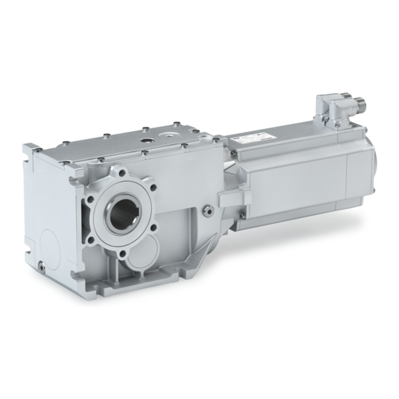
Page 9: Features
Product information Features Features The following figure provides an overview of the elements and connections on the product. Their position, size and appearance may vary. Ventilation Temperature monitoring (depending on the mounting position) Oil filler plug (depending on the mounting position) Motor connection Remove oil control plug (depending on the mounting position) -
Page 10: The Modular System
Product information The modular system The modular system Values printed in bold are standard designs. Values that are not printed in bold are potential extensions, some of them including a surcharge. Geared motors up to 450 Nm Gearbox g500-B110 g500-B240 g500-B450 Min. - Page 11 Product information The modular system Geared motors from 600 Nm to 4300 Nm Gearbox g500-B600 g500-B820 g500-B1500 g500-B2700 g500-B4300 Min. motor assignment m850-S120 m850-S120 m850-S120 m850-S120 m850-S120 Max. motor assignment m850-S190 m850-S190 m850-S190 m850-S190 m850-S190 Technical data Max. output torque 1500 2700 4300...
-
Page 12: Designs
Product information The modular system Designs Designs Gearbox designs Please observe the available gearbox designs! 4The modular system ^ 10 g500-B45 ... B4300 Hollow shaft, with foot Without centring (HBR) With centring (HAR) Flange with through holes (HAK) Hollow shaft with shrink disc, with foot Without centring (SBR) With centring (SAR) Flange with through holes (SAK) - Page 13 Product information The modular system Designs Models at the output Motor connection ICN connector ICN hybrid connector for One Cable Technology (OCT) Cooling: Self-ventilated Feedback Feedback and brake...
-
Page 14: Mounting Positions
Product information The modular system Mounting positions Mounting positions Details of the mounting position are needed to ensure the corresponding lubricant amount, position of the ventilation, oil checks and oil drain plug on the gearbox. To reduce the number of different versions, the gearboxes can also be ordered with combined mounting positions: g500-B110 ... - Page 15 Product information The modular system Mounting positions Position of the ICN connectors Position of the solid shaft Double-ended output shaft journal "L+R". Position of the hollow shaft with shrink disc Output flange and shrink disc are not possible in the same position.
- Page 16 Product information The modular system Mounting positions Position of the output flange Output flange on both sides "L+R". Position of the torque plate on the threaded pitch circle Position of the torque plate Angle of the torque plate g500-B45 ... B110 90°...
- Page 17 Product information The modular system Mounting positions Position of the torque plate on the housing foot Position of the torque plate Position of the rubber buffer on the torque plate...
-
Page 18: Information On Project Planning
Information on project planning Safety instructions Information on project planning Safety instructions Disregarding the following basic safety measures and safety information may lead to severe personal injury and damage to property! Observe all specifications of the corresponding documentation supplied. This is the precondition for safe and trouble-free operation and for obtaining the product features specified. -
Page 19: Basic Safety Instructions
The procedural notes and circuit details described are only proposals. It is up to the user to check whether they can be adapted to the particular applications. Lenze does not take any responsibility for the suitability of the procedures and circuit proposals described. -
Page 20: Application As Directed
Information on project planning Safety instructions Application as directed Application as directed The product must only be actuated under the operating conditions and power limits • specified in this documentation. The product meets the protection requirements of 2014/35/EU: Low-Voltage Directive. •... -
Page 21: Residual Hazards
Information on project planning Safety instructions Residual hazards Residual hazards Even if notes given are taken into consideration and protective measures are implemented, the occurrence of residual risks cannot be fully prevented. The user must take the residual hazards mentioned into consideration in the risk assessment for his/her machine/system. - Page 22 Information on project planning Safety instructions Residual hazards Motor protection Version with plug: • Never disconnect the plug when energized. The plug could be destroyed. Switch off the voltage supply or disable the inverter prior to disconnecting the plug. Installed thermal detectors are no full protection for the machine. •...
-
Page 23: General Information
• and the foundations. NOTICE A thermal check with the Drive Solution Designer (DSD) or contacting your Lenze representative is required if ▶ the input speed n > 1500 rpm is fallen below in case of the gearbox ratios given in the following. -
Page 24: Drive Dimensioning
With the «Drive Solution Designer«, you can design the drive both quickly and to a high quality. The software contains profound and proven expertise with regard to drive applications and mechatronic drive components. Please get in touch with your Lenze representative. NOTICE The dimensioning is suitable for the operating modes S1, S2, S3 and S6... - Page 25 Information on project planning Drive dimensioning Workflow S1 operation S2, S3 and S6 operation Check operating conditions Define required input variables Determine correction factor Operating modes and operating time Operating modes and operating time Ambient temperature and installation height Ambient temperature and installation height Mounting position Mounting position Mean speed utilization...
- Page 26 50 °C 0.80 0.76 60 °C 0.60 0.57 Mounting position Gearboxes Mounting position Correction factor g500-H 1.00 0.70 0.80 0.80 1.00 1.00 g500-S 1.00 0.70 0.80 0.85 0.80 0.90 g500-B 1.00 0.70 0.80 0.80 0.80 0.80 4Selection tables ^ 64...
- Page 27 Operating mode S6 0.16 0.15 0.50 0.25 1.00 0.40 1.00 0.60 Gearbox efficiency Gearboxes Gearbox efficiency η g500-B 2-stage 0.96 3-stage 0.95 4-stage 0.94 Determine product on the basis of the forces Transmission element Gear wheels Sprockets Toothed belt pulleys Narrow V-belt...
- Page 28 Information on project planning Drive dimensioning Determination of the required gearbox load capacity Define the required load factor at runtime t Runtime t ≤ 10 % Take the load factor k from diagram into account Runtime t > 10 % Take intensity k from calculation into account Calculate intensity...
- Page 29 Information on project planning Drive dimensioning Order data Ratio i Geared motor Example 3.267 g500-H140 m850-S120/S3960 Example 3.661 g500-S130 m850-S120/S3960 Example 4.889 g500-B240 m850-S120/S3960 Operating modes S2, S3, and S6 Calculation of the required drive power Calculation Result Unit Output torque ≥...
-
Page 30: Final Configuration
Information on project planning Final configuration Final configuration Screening Connection dimensions Output shaft Output flange/foot Mounting position Geared motor Connector/terminal box Driven shaft/output flange Product extensions Torque plate Shaft cover Connector/terminal box Brake Feedback Blower Temperature monitoring Second shaft end Handwheel Protection cover More information about the final configuration:... -
Page 31: Surface And Corrosion Protection
Various surface coatings ensure that the motors operate reliably even at high air humidity, in outdoor installation or in the presence of atmospheric impurities. Any color from the "RAL Classic" collection can be chosen for the top coat. The OKS-XL (extra Large) version requires a check by your responsible Lenze subsidiary. Surface and corrosion... -
Page 32: Lubricants
Information on project planning Final configuration Lubricants Lubricants The following gearboxes are lubricated for life: g500-B45 • g500-B110 • g500-B240 • Recommended lubricants: Lubricant CLP HC 220 CLP HC 320 CLP HC 46 CLP HC 220 USDA H1 USDA H1 Ambient temperature -30 …... -
Page 33: Ventilation
Information on project planning Final configuration Ventilation Ventilation No ventilation measures are required for the gearboxes g500-B45 … B240. The gearbox g500-B240 can optionally be fitted with ventilation units. From g500-B450 onwards, the gearboxes are supplied with ventilation units as standard. - Page 34 Information on project planning Final configuration Ventilation g500-B240 Mounting position M1 (A) Mounting position M2 (D) Mounting position M3 (B) Filling and ventilation Control Drain...
- Page 35 Information on project planning Final configuration Ventilation Mounting position M4 (C) Mounting position M5 (E) Mounting position M6 (F) Filling and ventilation Control Drain...
- Page 36 Information on project planning Final configuration Ventilation g500-B450 Mounting position M1 (A) Mounting position M2 (D) Mounting position M3 (B) Filling and ventilation Control Drain...
- Page 37 Information on project planning Final configuration Ventilation Mounting position M4 (C) Mounting position M5 (E) Mounting position M6 (F) Filling and ventilation Control Drain...
- Page 38 Information on project planning Final configuration Ventilation g500-B600 ... B4300 Mounting position M1 (A) Mounting position M2 (D) Mounting position M3 (B) Filling and ventilation Control Drain ① ② ④ ⑤ ③ g500-B600 ① g500-B820 ② g500-B1500 ③ g500-B2700 ④ g500-B4300 ⑤...
- Page 39 Information on project planning Final configuration Ventilation Mounting position M4 (C) Mounting position M5 (E) Mounting position M6 (F) Filling and ventilation ④ ③ ⑤ ④ ① ⑤ ② ① ③ ② ③ Control ③ Drain g500-B600 □ g500-B820 □ g500-B1500 □...
- Page 40 Information on project planning Final configuration Ventilation Gearbox with oil compensation reservoir for mounting position M4 (C) In order to guarantee a reliable lubrication of the toothed parts in mounting position M4 (C) (motor is on the gearbox vertical from the top), a high filling level is required in the gearbox. As a result of the reduced volume of air in the gearbox, this may lead to oil escaping from the ventilation at higher input speeds.
- Page 41 Information on project planning Final configuration Ventilation g500-B1500 g500-B2700 g500-B4300 Gearbox ratio Min. input speed Gearbox ratio Min. input speed Gearbox ratio Min. input speed 6.866 2000 6.918 2000 5.488 2000 9.516 2000 8.793 2000 6.976 2000 10.902 2000 11.713 2000 9.156 2000...
-
Page 42: Information On Mechanical Installation
• nameplate and in this documentation. Ambient media − especially chemically aggressive ones − may damage shaft sealing rings, • lacquers and plastics. Lenze offers special surface and corrosion protection in this case. • Transport Ensure appropriate handling. • Make sure that all component parts are securely mounted. Secure or remove loose •... -
Page 43: Information On Electrical Installation
The manufacturer of the system or machine is responsible for adherence to the limits • required in connection with EMC legislation. Preparation The notes for the electrical connection can be found in the enclosed mounting instructions. EMC-compliant wiring The EMC-compliant wiring is described in detail in the documentation of the Lenze inverters. -
Page 44: Technical Data
The ratings apply to the operating mode S1 (acc. to EN 60034). • NOTICE In case of other operating conditions, the achievable values can differ for those mentioned. ▶ In case of extreme operating conditions, please get in touch with your Lenze representative. -
Page 45: Standards And Operating Conditions
Technical data Standards and operating conditions Conformities and approvals Standards and operating conditions Conformities and approvals Conformities 2011/65/EU RoHS Directive 2014/35/EU Low-Voltage Directive 2014/30/EU EMC Directive (reference: CE-typical drive system) TP TR 004/2011 Eurasian conformity: Safety of low voltage equipment TP TC 020/2011 Eurasian conformity: Electromagnetic compatibility of technical means Approvals... -
Page 46: Data Overview
Technical data Data overview Data overview In order to calculate the exact ratio, the number of teeth z (driven) can be divided by the number of teeth z (driving). These are rounded values. The rated torque can be gathered from the last digits of the product name e.g. g500-B110 (110 Nm). - Page 47 Technical data Data overview g500-B110, 2-stage Max. output torque Ratio Number of teeth Backlash Standard 2,max ± 20 % 5.185 5.963 7.111 8.178 9.101 1720 10.466 1978 11.449 2576 12.698 14.603 15.556 17.889 19.556 22.489 1012 25.185 28.963 31.919 3160 36.707 3634 37.400...
- Page 48 Technical data Data overview g500-B110, 3-stage Max. output torque Ratio Number of teeth Backlash Standard 2,max ± 20 % 107.090 20240 114.074 3080 131.185 3542 143.407 3872 164.919 22264 178.095 3740 200.151 45034 224.148 6052 257.770 34799 284.081 28124 326.693 161713 356.000 409.400...
- Page 49 Technical data Data overview g500-B240, 3-stage Max. output torque Ratio Number of teeth Backlash Standard 2,max ± 20 % 68.459 43129 77.741 48977 87.563 11033 99.437 12529 113.673 17051 129.087 19363 145.674 61183 165.426 69479 188.442 31093 213.994 35309 245.178 11033 278.422 12529...
- Page 50 Technical data Data overview g500-B450, 3-stage Max. output torque Ratio Number of teeth Backlash Standard 2,max ± 20 % 5.002 2401 6.860 9.315 3577 10.328 2107 12.775 14.165 1204 16.349 3139 17.885 3577 19.831 8428 22.813 25.294 27.945 3577 30.985 2107 36.373 20951...
- Page 51 Technical data Data overview g500-B450, 4-stage Max. output torque Ratio Number of teeth Backlash Standard 2,max ± 20 % 204.072 318353 1560 230.605 44968 255.691 847616 3315 295.120 34529 322.847 314776 357.968 5933312 16575 411.795 16060 456.591 302720 504.449 39347 559.324 370832 656.584...
- Page 52 Technical data Data overview g500-B600, 3-stage Max. output torque Ratio Number of teeth Backlash Standard 2,max ± 20 % 5.067 6293 1242 6.949 7192 1035 7.617 15631 2052 10.741 13.369 13717 1026 14.730 18.851 24940 1323 20.622 22.852 15631 25.347 2408 26.061 29.744...
- Page 53 Technical data Data overview g500-B600, 4-stage Max. output torque Ratio Number of teeth Backlash Standard 2,max ± 20 % 201.089 286552 1425 227.943 112832 252.594 86387 283.539 46784 328.773 505981 1539 366.933 5504 406.614 23177 468.027 68800 529.244 271502 573.333 1720 642.309 1098349...
- Page 54 Technical data Data overview g500-B820, 3-stage Max. output torque Ratio Number of teeth Backlash Standard 2,max ± 20 % 4.958 6.800 7.618 8.517 9.520 10.447 11.680 12.143 13.370 1591 14.626 6216 16.352 2044 18.655 2220 20.857 22.853 25.550 26.324 8687 29.745 1517 32.291...
- Page 55 Technical data Data overview g500-B820, 4-stage Max. output torque Ratio Number of teeth Backlash Standard 2,max ± 20 % 201.818 2220 225.636 2482 256.175 70448 286.408 1181432 4125 321.788 10619 359.765 356167 400.273 4403 468.265 2086121 4455 518.000 579.133 8687 674.222 6068 753.793...
- Page 56 Technical data Data overview g500-B1500, 3-stage Max. output torque Ratio Number of teeth Backlash Standard 2,max ± 20 % 6.866 1792 1006 9.516 1456 1330 10.902 36992 3393 1461 11.985 3128 1118 13.118 50176 3825 1500 15.111 1500 16.611 1500 18.598 2176 1500...
- Page 57 Technical data Data overview g500-B1500, 4-stage Max. output torque Ratio Number of teeth Backlash Standard 2,max ± 20 % 1500 204.476 29240 1500 224.773 4945 1500 250.483 35819 1500 275.347 48461 1500 326.025 419594 1287 1500 358.388 283843 1500 405.543 173978 1500 445.799...
- Page 58 Technical data Data overview g500-B2700, 3-stage Max. output torque Ratio Number of teeth Backlash Standard 2,max ± 20 % 1446 6.918 28917 4180 1528 8.793 41769 4750 2212 11.713 2448 2262 12.863 18819 1463 2380 14.888 7072 2429 16.351 54366 3325 2579 19.542...
- Page 59 Technical data Data overview g500-B2700, 4-stage Max. output torque Ratio Number of teeth Backlash Standard 2,max ± 20 % 2700 205.407 5546 2700 225.581 113693 2700 265.150 178976 2700 291.191 65518 2700 332.564 188564 2700 365.227 1932781 5292 2700 414.296 11186 2700 454.986...
- Page 60 Technical data Data overview g500-B4300, 3-stage Max. output torque Ratio Number of teeth Backlash Standard 2,max ± 20 % 2160 5.488 1147 2400 6.976 29822 4275 2700 9.156 98642 10773 3950 10.137 67797 6688 4250 11.080 23157 2090 4300 12.885 97929 7600 4300...
- Page 61 Technical data Data overview g500-B4300, 4-stage Max. output torque Ratio Number of teeth Backlash Standard 2,max ± 20 % 4300 205.348 52569 4300 224.446 53867 4300 265.073 106029 4300 278.438 4455 4300 304.333 4300 369.548 15521 4300 414.176 106029 4300 452.696 108647 4300...
-
Page 62: Radial Forces And Axial Forces
Technical data Radial forces and axial forces Radial forces and axial forces Permissible radial force The calculation of the permissible radial force must take account of the additional load factor rad, perm rad,max Permissible axial force If there is no radial force, the maximum axial force is 50% of the value in the table F rad,max = 0.5 x F ax, zul... - Page 63 1.3 and an input speed of 1400 rpm. In case of different operating conditions, considerably higher forces can be transmitted. Please get in touch with your Lenze representative A hollow shaft with shrink disc (SAR/SBR/SCR/SDR/SAK/SCK) requires a check by Lenze.
-
Page 64: Selection Tables
Technical data Selection tables Selection tables Notes on the selection tables The selection tables represent the available combinations of gearbox, number of stages, ratio and motor for the mounting position M1. They only serve as a rough overview. The following legend shows the layout of the selection tables: Example Explanation Inverter power supply 400 V, self-ventilated motors... -
Page 65: Inverter Mains Connection 400 V, Self-Ventilated Motors
Technical data Selection tables Inverter mains connection 400 V, Self-ventilated motors Inverter mains connection 400 V, Self-ventilated motors 2 kW Inverter operation Geared motor Number of stages g500- m850 2, max 2, th kgcm² 22.0 67.0 8.244 4.889 B240 120S40 24.0 69.0 7.293... - Page 66 Technical data Selection tables Inverter mains connection 400 V, Self-ventilated motors Inverter operation Geared motor Number of stages g500- m850 2, max 2, th kgcm² 95.1 8.099 32.439 B600 120S40 6.652 33.433 B240 120S40 6.811 36.373 B450 120S40 6.980 36.999 B600 120S40 7.136...
- Page 67 Technical data Selection tables Inverter mains connection 400 V, Self-ventilated motors Inverter operation Geared motor Number of stages g500- m850 2, max 2, th kgcm² 26.4 1500 26.4 7.203 149.949 B1500 120S40 25.9 2110 25.9 8.699 153.185 B2700 120S40 25.9 2109 25.9 8.917...
- Page 68 Technical data Selection tables Inverter mains connection 400 V, Self-ventilated motors 2.9 kW Inverter operation Geared motor Number of stages g500- m850 2, max 2, th kgcm² 29.0 88.0 18.672 3.565 B240 140S32 39.0 17.444 4.889 B240 140S32 40.0 20.060 5.002 B450 140S32...
- Page 69 Technical data Selection tables Inverter mains connection 400 V, Self-ventilated motors Inverter operation Geared motor Number of stages g500- m850 2, max 2, th kgcm² 37.870 25.365 B4300 140S32 17.253 25.550 B820 140S32 82.0 18.582 26.061 B600 140S32 87.1 18.777 26.324 B820 140S32...
- Page 70 Technical data Selection tables Inverter mains connection 400 V, Self-ventilated motors Inverter operation Geared motor Number of stages g500- m850 2, max 2, th kgcm² 33.2 2407 33.2 20.694 97.453 B4300 140S32 31.6 1500 31.6 17.305 102.396 B1500 140S32 30.4 2631 30.4 20.660...
- Page 71 Technical data Selection tables Inverter mains connection 400 V, Self-ventilated motors 3.1 kW Inverter operation Geared motor Number of stages g500- m850 2, max 2, th kgcm² 25.0 1111 98.0 15.372 3.565 B240 120M40 34.0 14.144 4.889 B240 120M40 35.0 16.760 5.002 B450...
- Page 72 Technical data Selection tables Inverter mains connection 400 V, Self-ventilated motors Inverter operation Geared motor Number of stages g500- m850 2, max 2, th kgcm² 98.2 98.2 12.702 40.330 B450 120M40 95.8 71.0 14.039 41.325 B820 120M40 94.4 94.4 13.076 41.940 B600 120M40...
- Page 73 Technical data Selection tables Inverter mains connection 400 V, Self-ventilated motors Inverter operation Geared motor Number of stages g500- m850 2, max 2, th kgcm² 1832 14.9 4300 14.9 13.671 265.073 B4300 120M40 1924 14.2 4300 14.2 13.390 278.438 B4300 120M40 2012 13.6...
- Page 74 Technical data Selection tables Inverter mains connection 400 V, Self-ventilated motors 3.7 kW Inverter operation Geared motor Number of stages g500- m850 2, max 2, th kgcm² 30.0 1111 21.172 3.565 B240 120L40 42.0 19.944 4.889 B240 120L40 42.0 29.722 4.958 B820 120L40...
- Page 75 Technical data Selection tables Inverter mains connection 400 V, Self-ventilated motors Inverter operation Geared motor Number of stages g500- m850 2, max 2, th kgcm² 96.3 20.377 25.347 B600 120L40 1060 40.370 25.365 B4300 120L40 19.753 25.550 B820 120L40 79.4 21.082 26.061 B600...
- Page 76 Technical data Selection tables Inverter mains connection 400 V, Self-ventilated motors Inverter operation Geared motor Number of stages g500- m850 2, max 2, th kgcm² 42.5 1923 42.5 20.104 93.283 B2700 120L40 40.6 2700 34.0 22.657 97.481 B2700 120L40 40.6 3499 35.7 23.194...
- Page 77 Technical data Selection tables Inverter mains connection 400 V, Self-ventilated motors 4.8 kW Inverter operation Geared motor Number of stages g500- m850 2, max 2, th kgcm² 47.0 33.072 3.565 B240 140M32 65.0 31.844 4.889 B240 140M32 66.0 41.622 4.958 B820 140M32 67.0...
- Page 78 Technical data Selection tables Inverter mains connection 400 V, Self-ventilated motors Inverter operation Geared motor Number of stages g500- m850 2, max 2, th kgcm² 75.3 33.177 26.324 B820 140M32 1363 42.288 26.814 B2700 140M32 1484 34.394 29.206 B1500 140M32 1496 91.5 42.099...
- Page 79 Technical data Selection tables Inverter mains connection 400 V, Self-ventilated motors Inverter operation Geared motor Number of stages g500- m850 2, max 2, th kgcm² 2701 15.9 4300 15.9 31.864 203.143 B4300 140M32 2934 14.4 4300 14.4 31.231 224.446 B4300 140M32 3124 13.8...
- Page 80 Technical data Selection tables Inverter mains connection 400 V, Self-ventilated motors 5 kW Inverter operation Geared motor Number of stages g500- m850 2, max 2, th kgcm² 75.0 72.322 4.958 B820 190S30 77.0 67.531 5.067 B600 190S30 67.511 6.800 B820 190S30 64.963 6.949...
- Page 81 Technical data Selection tables Inverter mains connection 400 V, Self-ventilated motors Inverter operation Geared motor Number of stages g500- m850 2, max 2, th kgcm² 92.9 60.6 63.043 32.291 B820 190S30 92.2 1500 92.2 64.063 32.547 B1500 190S30 91.3 2217 88.5 70.048 32.873...
- Page 82 Technical data Selection tables Inverter mains connection 400 V, Self-ventilated motors 5.9 kW Inverter operation Geared motor Number of stages g500- m850 2, max 2, th kgcm² 82.0 56.122 4.958 B820 140L32 83.0 48.960 5.002 B450 140L32 84.0 51.331 5.067 B600 140L32 51.311...
- Page 83 Technical data Selection tables Inverter mains connection 400 V, Self-ventilated motors Inverter operation Geared motor Number of stages g500- m850 2, max 2, th kgcm² 70.8 46.777 25.347 B600 140L32 1778 66.770 25.365 B4300 140L32 46.153 25.550 B820 140L32 57.9 47.482 26.061 B600...
- Page 84 Technical data Selection tables Inverter mains connection 400 V, Self-ventilated motors Inverter operation Geared motor Number of stages g500- m850 2, max 2, th kgcm² 2149 24.9 2700 22.1 45.713 129.996 B2700 140L32 2531 21.2 4300 21.2 47.017 153.141 B4300 140L32 2532 21.2...
- Page 85 Technical data Selection tables Inverter mains connection 400 V, Self-ventilated motors 7.5 kW Inverter operation Geared motor Number of stages g500- m850 2, max 2, th kgcm² 128.522 4.958 B820 190M30 123.731 5.067 B600 190M30 123.711 6.800 B820 190M30 138.952 6.866 B1500 190M30...
- Page 86 Technical data Selection tables Inverter mains connection 400 V, Self-ventilated motors Inverter operation Geared motor Number of stages g500- m850 2, max 2, th kgcm² 83.9 1500 75.2 120.210 35.778 B1500 190M30 83.1 2700 74.9 126.122 36.102 B2700 190M30 82.1 1500 46.4 123.890...
- Page 87 Technical data Selection tables Inverter mains connection 400 V, Self-ventilated motors 9.2 kW Inverter operation Geared motor Number of stages g500- m850 2, max 2, th kgcm² 204.522 4.958 B820 190L25 199.731 5.067 B600 190L25 199.711 6.800 B820 190L25 214.952 6.866 B1500 190L25...
- Page 88 Technical data Selection tables Inverter mains connection 400 V, Self-ventilated motors Inverter operation Geared motor Number of stages g500- m850 2, max 2, th kgcm² 1184 70.8 4300 50.8 217.646 35.607 B4300 190L25 1189 70.4 1500 65.3 196.210 35.778 B1500 190L25 1200 69.8...
-
Page 89: Dimensions
Technical data Dimensions Dimensions Notes on the basic dimensions Gearboxes Without pre-stage With pre-stage g500-B45 2-stufig g500-B110 2-stage 3-stage g500-B240 2-/3-stage 4-stage g500-B450 ... B4300 3-stage 4-stage The ratio range of gearboxes with pre-stage is extended via an additional housing with gear stage between the gearbox and motor. - Page 90 If the mounting area (foot support) towards the motor is longer than the gearbox foot, some motors collide with the mounting area! For an accurate check of the geometrical data, Lenze recommends the use of the »Product Finder« at www.Lenze.com.
-
Page 91: Basic Dimensions
Technical data Dimensions Basic dimensions Basic dimensions g500-B110, 2-stage Gearbox version: Hollow shaft with foot (HAR/HBR/HAK) Motor m850- S120/S3960 S120/M3960 Total length Motor length Length of motor options Δ L Motor diameter Motor/connection distance... - Page 92 Technical data Dimensions Basic dimensions g500-B110, 2-stage Gearbox version: Hollow shaft with shrink disc, with foot (SAR/SBR/SAK) Motor m850- S120/S3960 S120/M3960 Total length Motor length Length of motor options Δ L Motor diameter Motor/connection distance...
- Page 93 Technical data Dimensions Basic dimensions g500-B110, 2-stage Gearbox version: Solid shaft with foot (VAR/VBR/VAK) Motor m850- S120/S3960 S120/M3960 Total length Motor length Length of motor options Δ L Motor diameter Motor/connection distance...
- Page 94 Technical data Dimensions Basic dimensions g500-B240, 2-/3-stage Gearbox version: Hollow shaft with foot (HAR/HBR/HAK) Motor m850- S120/S3960 S120/M3960 S120/L3960 S140/S3240 S140/M3240 Total length Motor length Length of motor options Δ L Motor diameter Motor/connection distance...
- Page 95 Technical data Dimensions Basic dimensions g500-B240, 2-/3-stage Gearbox version: Hollow shaft with shrink disc, with foot (SAR/SBR/SAK) Motor m850- S120/S3960 S120/M3960 S120/L3960 S140/S3240 S140/M3240 Total length Motor length Length of motor options Δ L Motor diameter Motor/connection distance...
- Page 96 Technical data Dimensions Basic dimensions g500-B240, 2-/3-stage Gearbox version: Solid shaft with foot (VAR/VBR/VAK) Motor m850- S120/S3960 S120/M3960 S120/L3960 S140/S3240 S140/M3240 Total length Motor length Length of motor options Δ L Motor diameter Motor/connection distance...
- Page 97 Technical data Dimensions Basic dimensions g500-B450, 3-stage Gearbox version: Hollow shaft with foot (HAR/HBR/HAK) Motor m850- S120/S3960 S120/M3960 S120/L3960 S140/S3240 S140/M3240 S140/L3240 Total length Motor length Length of motor options Δ L Motor diameter Motor/connection distance...
- Page 98 Technical data Dimensions Basic dimensions g500-B450, 3-stage Gearbox version: Hollow shaft with shrink disc, with foot (SAR/SBR/SAK) Motor m850- S120/S3960 S120/M3960 S120/L3960 S140/S3240 S140/M3240 S140/L3240 Total length Motor length Length of motor options Δ L Motor diameter Motor/connection distance...
- Page 99 Technical data Dimensions Basic dimensions g500-B450, 3-stage Gearbox version: Solid shaft with foot (VAR/VBR/VAK) Motor m850- S120/S3960 S120/M3960 S120/L3960 S140/S3240 S140/M3240 S140/L3240 Total length Motor length Length of motor options Δ L Motor diameter Motor/connection distance...
- Page 100 Technical data Dimensions Basic dimensions g500-B600, 3-stage Gearbox version: Hollow shaft with foot (HAR/HBR/HAK) Motor m850- S120/ S120/ S120/ S140/ S140/ S140/ S190/ S190/ S190/ S3960 M3960 L3960 S3240 M3240 L3240 S3000 M3000 L2520 Total length Motor length Length of motor options Δ...
- Page 101 Technical data Dimensions Basic dimensions g500-B600, 3-stage Gearbox version: Hollow shaft with shrink disc, with foot (SAR/SBR/SAK) Motor m850- S120/ S120/ S120/ S140/ S140/ S140/ S190/ S190/ S190/ S3960 M3960 L3960 S3240 M3240 L3240 S3000 M3000 L2520 Total length Motor length Length of motor options Δ...
- Page 102 Technical data Dimensions Basic dimensions g500-B600, 3-stage Gearbox version: Solid shaft with foot (VAR/VBR/VAK) Motor m850- S120/ S120/ S120/ S140/ S140/ S140/ S190/ S190/ S190/ S3960 M3960 L3960 S3240 M3240 L3240 S3000 M3000 L2520 Total length Motor length Length of motor options Δ...
- Page 103 Technical data Dimensions Basic dimensions g500-B820, 3-stage Gearbox version: Hollow shaft with foot (HAR/HBR/HAK) Motor m850- S120/ S120/ S120/ S140/ S140/ S140/ S190/ S190/ S190/ S3960 M3960 L3960 S3240 M3240 L3240 S3000 M3000 L2520 Total length Motor length Length of motor options Δ...
- Page 104 Technical data Dimensions Basic dimensions g500-B820, 3-stage Gearbox version: Hollow shaft with shrink disc, with foot (SAR/SBR/SAK) Motor m850- S120/ S120/ S120/ S140/ S140/ S140/ S190/ S190/ S190/ S3960 M3960 L3960 S3240 M3240 L3240 S3000 M3000 L2520 Total length Motor length Length of motor options Δ...
- Page 105 Technical data Dimensions Basic dimensions g500-B820, 3-stage Gearbox version: Solid shaft with foot (VAR/VBR/VAK) Motor m850- S120/ S120/ S120/ S140/ S140/ S140/ S190/ S190/ S190/ S3960 M3960 L3960 S3240 M3240 L3240 S3000 M3000 L2520 Total length Motor length Length of motor options Δ...
- Page 106 Technical data Dimensions Basic dimensions g500-B1500, 3-stage Gearbox version: Hollow shaft with foot (HAR/HBR/HAK) Motor m850- S120/ S120/ S120/ S140/ S140/ S140/ S190/ S190/ S190/ S3960 M3960 L3960 S3240 M3240 L3240 S3000 M3000 L2520 Total length Motor length Length of motor options Δ...
- Page 107 Technical data Dimensions Basic dimensions g500-B1500, 3-stage Gearbox version: Hollow shaft with shrink disc, with foot (SAR/SBR/SAK) Motor m850- S120/ S120/ S120/ S140/ S140/ S140/ S190/ S190/ S190/ S3960 M3960 L3960 S3240 M3240 L3240 S3000 M3000 L2520 Total length Motor length Length of motor options Δ...
- Page 108 Technical data Dimensions Basic dimensions g500-B1500, 3-stage Gearbox version: Solid shaft with foot (VAR/VBR/VAK) Motor m850- S120/ S120/ S120/ S140/ S140/ S140/ S190/ S190/ S190/ S3960 M3960 L3960 S3240 M3240 L3240 S3000 M3000 L2520 Total length Motor length Length of motor options Δ...
- Page 109 Technical data Dimensions Basic dimensions g500-B2700, 3-stage Gearbox version: Hollow shaft with foot (HAR/HBR/HAK) Motor m850- S120/ S120/ S120/ S140/ S140/ S140/ S190/ S190/ S190/ S3960 M3960 L3960 S3240 M3240 L3240 S3000 M3000 L2520 Total length Motor length Length of motor options Δ...
- Page 110 Technical data Dimensions Basic dimensions g500-B2700, 3-stage Gearbox version: Hollow shaft with shrink disc, with foot (SAR/SBR/SAK) Motor m850- S120/ S120/ S120/ S140/ S140/ S140/ S190/ S190/ S190/ S3960 M3960 L3960 S3240 M3240 L3240 S3000 M3000 L2520 Total length Motor length Length of motor options Δ...
- Page 111 Technical data Dimensions Basic dimensions g500-B2700, 3-stage Gearbox version: Solid shaft with foot (VAR/VBR/VAK) Motor m850- S120/ S120/ S120/ S140/ S140/ S140/ S190/ S190/ S190/ S3960 M3960 L3960 S3240 M3240 L3240 S3000 M3000 L2520 Total length Motor length Length of motor options Δ...
- Page 112 Technical data Dimensions Basic dimensions g500-B4300, 3-stage Gearbox version: Hollow shaft with foot (HAR/HBR/HAK) Motor m850- S120/ S120/ S120/ S140/ S140/ S140/ S190/ S190/ S190/ S3960 M3960 L3960 S3240 M3240 L3240 S3000 M3000 L2520 Total length Motor length Length of motor options Δ...
- Page 113 Technical data Dimensions Basic dimensions g500-B4300, 3-stage Gearbox version: Hollow shaft with shrink disc, with foot (SAR/SBR/SAK) Motor m850- S120/ S120/ S120/ S140/ S140/ S140/ S190/ S190/ S190/ S3960 M3960 L3960 S3240 M3240 L3240 S3000 M3000 L2520 Total length Motor length Length of motor options Δ...
- Page 114 Technical data Dimensions Basic dimensions g500-B4300, 3-stage Gearbox version: Solid shaft with foot (VAR/VBR/VAK) Motor m850- S120/ S120/ S120/ S140/ S140/ S140/ S190/ S190/ S190/ S3960 M3960 L3960 S3240 M3240 L3240 S3000 M3000 L2520 Total length Motor length Length of motor options Δ...
-
Page 115: Gearbox With Pre-Stage
Technical data Dimensions Gearbox with pre-stage Gearbox with pre-stage g500-B110, 3-stage g500-B240 ... B4300, 4-stage The geared motor dimensions can be found in the basic dimensions, except the total length "L" and the center distance "a". 4Basic dimensions ^ 91 The total length "L"... -
Page 116: Weights
Technical data Weights Basic weights Weights Basic weights The basic weights are listed in the selection tables. Weights with lubricant for mounting position M1, all data approximate values. The exact values can be found in the delivery documents tables 4Selection ^ 64 Observe weights ... -
Page 117: Product Extensions
Product extensions Torque plates Product extensions Torque plates The torque support is usually effected by means of the foot or flange. The torque plates that can be fitted are another possibility. In this case, the torque support is provided only via one point and is suitable for shaft-mounted gearboxes, among other things. - Page 118 Product extensions Torque plates Torque plate on threaded pitch circle g500-B45 ... B110 Gearboxes Dimensions g500-B45 12.0 20,0 42.0 g500-B110 13.0 10.0 25.0 54.0 11.0...
- Page 119 Product extensions Torque plates g500-B240 ... B600 Gearboxes Dimensions g500-B240 34.0 23.5 27.5 38.5 16.0 45.0 15.0 g500-B450 40,0 29.0 32.0 44.5 20,0 50.0 18.0 g500-B600 38.0 26.5 31.5 40,0 20,0 50.0 19.0...
- Page 120 Product extensions Torque plates g500-B820 ... B1500 Gearboxes Dimensions g500-B820 38.0 28.0 31.5 40,0 20,0 50.0 20.5 g500-B1500 44.0 32.0 36.0 46.0 25.0 65.0 24.0...
- Page 121 Product extensions Torque plates Torque plate on housing foot g500-B240...
- Page 122 Product extensions Torque plates g500-B450 e4001554_01...
- Page 123 Product extensions Torque plates g500-B600 ... B4300 Gearboxes Dimensions g500-B600 16.4 40,0 55.0 60.0 18.0 g500-B820 16.4 45.0 55.0 60.0 25.0 g500-B1500 16.4 52.5 55.0 60.0 25.0 g500-B2700 25.0 60.0 72.0 80.0 30.0 g500-B4300 25.0 70.0 92.0 40,0...
- Page 124 Product extensions Torque plates GKS compatible The connection dimensions are identical to the previous product GKS for these torque plates. The GKS gearbox can be replaced by the gearbox from the g500-B series. g500-B600 ... B4300 Gearboxes Dimensions Replacement Ø d Ø...
-
Page 125: Shaft Covers
Product extensions Shaft covers Shaft covers The shrink disc cover is provided for the shrink disc to be protected from contact. The hoseproof hollow shaft cover protects the hollow shaft from objects falling in. It is sealed by a flat gasket between cover and housing. Thus, the hollow shaft is protected from dust and water jets on this side. - Page 126 Product extensions Shaft covers Hollow shaft cover, hoseproof g500-B45 ..B4300 Product Dimensions g500-B45 55.0 g500-B110 65.0 g500-B240 75.0 g500-B450 79.5 g500-B600 90.0 g500-B820 97.0 g500-B1500 g500-B2700 g500-B4300...
-
Page 127: Motor Connection
In order to provide for a quick and error-free connection of Lenze motors to Lenze inverters, we recommend using prefabricated Lenze system cables. - Page 128 Product extensions Motor connection Connection via ICN connector Position of the connections Standard connection One Cable Technology (OCT) Position Meaning Position Meaning ICN-M23 connector, 6-pole For One Cable Technology (OCT) ICN-M40 connector, 8-pole ICN-M23 connector, hybrid • Power connection ICN-M40 connector, hybrid •...
- Page 129 Product extensions Motor connection Connection via ICN connector Standard connection Connection of power and brake ICN-M23 connector assignment 6-pole ICN M23 6-pole Contact Name Meaning PE conductor Holding brake DC +/AC Holding brake DC -/AC Power phase U Power phase V Power phase W ICN-M40 connector assignment 8-pole...
- Page 130 Product extensions Motor connection Connection via ICN connector Feedback and temperature monitoring connection ICN-M23 connector assignment Resolver Code 0° ICN M23 for resolvers Contact Name Meaning +Ref Transformer windings -Ref Transformer windings Supply: Electronic nameplate (Only for motors and inverters that support +VCC ETS this function) +COS...
- Page 131 Product extensions Motor connection Connection via ICN connector Motor/connector assignment NOTICE When making your selection, the motor data and permissible currents of the cables according to the system cable system manual must be observed. Power terminal connectors Motor code m850- S120/S3960 S120/M3960 S120/L3960...
- Page 132 Product extensions Motor connection Connection via ICN connector One Cable Technology (OCT) Connection of power, brake, feedback and temperature monitoring ICN-M23 connector assignment, hybrid For One Cable Technology (OCT) with digital absolute value encoder ICN M23 Hybrid for One Cable Technology (OCT) with digital absolute value encoder Contact Name Meaning...
- Page 133 Product extensions Motor connection Connection via ICN connector ICN-M40 connector assignment, hybrid For One Cable Technology (OCT) with digital absolute value encoder DSL1 DSL2 ICN M40 Hybrid for One Cable Technology (OCT) with digital absolute value encoder Contact Name Meaning Power phase U Power phase V Power phase W...
- Page 134 Product extensions Motor connection Connection via ICN connector Hybrid cables for One Cable Technology (OCT) Connector with bayonet lock ICN-M23 Hybrid Order code for hybrid cable 1.5 mm Cable length 2.0 m EYP0080A0020M11A00 Cable length 3.5 m EYP0080A0035M11A00 Cable length 5.0 m EYP0080A0050M11A00 Cable length 7.5 m EYP0080A0075M11A00...
-
Page 135: Brakes
If long motor supply cables are used, pay attention to the ohmic voltage drop along the cable and compensate for it with a higher voltage at the input end of the cable. The following applies to Lenze system cables: Resulting supply voltage ´... - Page 136 Product extensions Brakes NOTICE In case of travel axes, the compliance of the permissible ratio of mass inertia load/brake motor (J ) ensures that the permissible maximum switching energy of the brake will not be exceeded and at least the values given for the emergency stop functions from the given speed (see rated data) are applied.
-
Page 137: Spring-Applied Brakes
Product extensions Brakes Spring-applied brakes Spring-applied brakes Rated data NOTICE Engagement and disengagement times apply to rated voltage (± 0 %) and suppressor circuit of the brakes with a varistor with DC switching. Without a suppressor circuit, the times may be longer. -
Page 138: Feedback
Motors can perform speed-dependent safety functions for safe speed and/or safe relative position monitoring in a drive system by Lenze inverters or Controllers. In case of inverters, these functions are implemented by integrable safety modules and in case of Controllers by the additionally required Safety Controller. -
Page 139: Resolver
Product extensions Feedback Resolver Resolver The stator-supplied, 2-pole resolver with two stator windings shifted by 90 degrees and a rotor winding with a transformer winding can record both the speed and the rotor position, just like a single-turn absolute value encoder. The rotor position can be determined within one mechanical motor revolution after a voltage failure. -
Page 140: Absolute Value Encoder
Product extensions Feedback Absolute value encoder Absolute value encoder Absolute value encoders can detect the speed, the rotor position, and the machine position with a very high resolution. They are used for the positioning of dynamic applications and do not require homing. With the aid of the open feedback protocol HIPERFACE DSL®... -
Page 141: Temperature Monitoring
Product extensions Temperature monitoring Thermal detectors PT1000 Temperature monitoring Thermal detectors PT1000 The thermal detector used continuously monitors the motor temperature. The temperature information is transferred to the inverter using the system cable of the feedback system. This is not a full motor protection! This makes it possible to determine the motor temperature in the permissible operating range with great accuracy. -
Page 142: Product Codes
Product codes Product codes Gearbox product code Example Product type Gearboxes Product family Generation Gearbox type Bevel gearbox Output torque 45 Nm 110 Nm 240 Nm 450 Nm 600 Nm 820 Nm 1500 Nm 2700 Nm 4300 Nm 8000 Nm 13000 Nm 20000 Nm Type of construction... - Page 143 40 x 100 rpm Degree of protection IP5x IP6x Cooling No cooling Brake attachment No brake Spring-applied brake Permanent magnet brake Encoder mounting Resolver Absolute value encoder Digital absolute value encoder Hiperface DSL® Product approval CE; cULus Manufacturer Lenze Internal key...
-
Page 144: Motor Data
Motor data Rated data Inverter mains connection 400 V, Self-ventilated motors Motor data Rated data Inverter mains connection 400 V, Self-ventilated motors Motor m850-S120/ m850-S120/ m850-S120/ m850-S140/ m850-S140/ m850-S140/ S3960 M3960 L3960 S3240 M3240 L3240 Standstill torque 6.50 11.0 15.0 11.0 21.0 28.0... - Page 145 Motor data Rated data Inverter mains connection 400 V, Self-ventilated motors Motor m850-S190/S3000 m850-S190/M3000 m850-S190/L2520 Standstill torque 27.0 46.0 67.0 Rated torque 16.0 24.0 35.0 rated Max. torque 71.0 Rated speed 3000 3000 2520 rated Max. speed 4500 4500 4500 Rated power rated Standstill current...
-
Page 146: Torque Characteristics
Torque characteristics Torque characteristics The torque/speed characteristic for your motor/inverter combination can be found on the Internet: http://www.lenze.com à Product Finder à M-n characteristics The following data apply to a mains voltage 3 x 400 V of the inverter. m850-S120/S3960... - Page 147 Motor data Torque characteristics m850-S120/L3960 = 4 V = 36 V = 3x I = 2x I 500 1000 1500 2000 2500 3000 3500 4000 4500 5000 5500 6000 r/min m850-S140/S3240 = 4 V = 36 V = 2x I 1000 1500 2000...
- Page 148 Motor data Torque characteristics m850-S140/M3240 = 4 V = 36 V = 3x I = 2x I 1000 1500 2000 2500 3000 3500 4000 4500 5000 r/min m850-S140/L3240 = 4 V = 36 V = 3x I = 2x I 1000 1500 2000...
- Page 149 Motor data Torque characteristics m850-S190/S3000 = 4 V = 36 V = 3x I = 2x I 1000 1500 2000 2500 3000 3500 4000 r/min m850-S190/M3000 = 4 V = 36 V = 3x I = 2x I 1000 1500 2000 2500 3000...
- Page 150 Motor data Torque characteristics m850-S190/L2520 = 4 V = 36 V = 3x I = 2x I 1000 1500 2000 2500 3000 3500 4000 r/min...
-
Page 151: Environmental Notes And Recycling
Lenze products and their packaging: Lenze products are partly subject to the EU Directive 2011/65/EU on the restriction of certain hazardous substances in electrical and electronic equipment (RoHS). This is documented accordingly in the EU declaration of conformity and with the CE mark. -
Page 152: Appendix
Appendix Good to know Approvals and directives Appendix Good to know Approvals and directives China Compulsory Certification documents the compliance with the legal product safety requirements of the PR of China - in accordance with Guobiao standards. CSA certificate, tested according to US and Canada standards Union Européenne documents the declaration of the manufacturer that EU Directives are complied with. -
Page 153: Operating Modes Of The Motor
Appendix Good to know Operating modes of the motor Operating modes of the motor In continuous operation a motor reaches its permissible temperature limit if it outputs the rated power dimensioned for continuous operation. However, if the motor is only subjected to load for a short time, the power output by the motor may be greater without the motor reaching its permissible temperature limit. -
Page 154: Enclosures
Appendix Good to know Enclosures Enclosures The degree of protection indicates the suitability of a motor for specific ambient conditions with regard to humidity as well as the protection against contact and the ingress of foreign particles. The degrees of protection are classified by EN 60529. The first code number after the code letters IP indicates the protection against the ingress of foreign particles and dust. - Page 156 © 06/2021 · 2.0 · www.Lenze.com...
Need help?
Do you have a question about the g500-B and is the answer not in the manual?
Questions and answers