Siemens SIMATIC IPC127E Operating Instructions Manual
Hide thumbs
Also See for SIMATIC IPC127E:
- Operating instructions manual (32 pages) ,
- Installation manual (9 pages)
Table of Contents
Advertisement
SIMATIC
Industrial PC
SIMATIC IPC127E
Operating Instructions
01/2019
A5E44296915-AA
Preface
___________________
Overview
___________________
Safety instructions
___________________
Mounting and connecting the
device
Commissioning the device
and device functions
___________________
Device maintenance and
repair
___________________
Technical specifications
___________________
Certificates and approvals
___________________
Directives and declarations
___________________
Dimension drawings
___________________
Hardware description
___________________
Technical support
___________________
Markings and symbols
___________________
List of abbreviations
1
2
3
4
5
6
7
8
9
10
A
B
C
Advertisement
Table of Contents

Related Manuals for Siemens SIMATIC IPC127E


Summary of Contents for Siemens SIMATIC IPC127E
- Page 1 Preface ___________________ Overview ___________________ SIMATIC Safety instructions ___________________ Mounting and connecting the device Industrial PC SIMATIC IPC127E Commissioning the device and device functions ___________________ Device maintenance and repair Operating Instructions ___________________ Technical specifications ___________________ Certificates and approvals ___________________ Directives and declarations...
- Page 2 Note the following: WARNING Siemens products may only be used for the applications described in the catalog and in the relevant technical documentation. If products and components from other manufacturers are used, these must be recommended or approved by Siemens. Proper transport, storage, installation, assembly, commissioning, operation and maintenance are required to ensure that the products operate safely and without any problems.
-
Page 3: Preface
USB stick in PDF format (in multiple languages). Conventions The terms "PC" and "device" are sometimes used to refer to the SIMATIC IPC127E in this documentation. Instead of the specific names of the operating system, we are using the abbreviation "Windows 10"... - Page 4 Preface SIMATIC IPC127E Operating Instructions, 01/2019, A5E44296915-AA...
-
Page 5: Table Of Contents
Switching the device on/off ..................... 38 Extended device functions ...................... 39 4.3.1 Monitoring functions ........................ 39 4.3.1.1 Overview of the monitoring functions ..................39 4.3.1.2 Temperature monitoring/display ..................... 40 4.3.1.3 Watchdog (WD) ........................41 4.3.1.4 Battery monitoring ........................42 SIMATIC IPC127E Operating Instructions, 01/2019, A5E44296915-AA... - Page 6 Korea ............................61 Directives and declarations ........................63 Electromagnetic Compatibility, Industrial and Residential Areas .......... 63 ESD guideline ........................64 Dimension drawings ..........................67 Dimension drawing basic device .................... 67 Dimension drawing Extended device ..................71 SIMATIC IPC127E Operating Instructions, 01/2019, A5E44296915-AA...
- Page 7 Markings and symbols ..........................87 Overview ..........................87 Safety ............................87 Operator controls ........................87 Certificates, approvals and markings ..................88 Interfaces ..........................89 List of abbreviations ..........................91 Abbreviations .......................... 91 Glossary ..............................93 Index ................................ 99 SIMATIC IPC127E Operating Instructions, 01/2019, A5E44296915-AA...
- Page 8 Table of contents SIMATIC IPC127E Operating Instructions, 01/2019, A5E44296915-AA...
-
Page 9: Overview
Overview Product description 1.1.1 Overview SIMATIC IPC127E provides high-level industrial functionality. ● Compact design ● High degree of ruggedness SIMATIC IPC127E Operating Instructions, 01/2019, A5E44296915-AA... -
Page 10: Design Of The Devices
The BIOS setup entry "After Power Failure" is preset to "Power On". This means the device is switched on with the on/off switch. You then do not need to press the on/off button to switch it on. SIMATIC IPC127E Operating Instructions, 01/2019, A5E44296915-AA... -
Page 11: Interfaces And Connections Of Extended Device
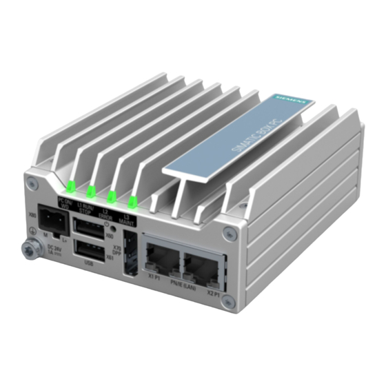
The BIOS setup entry "After Power Failure" is preset to "Power On". This means the device is switched on with the on/off switch. You then do not need to press the on/off button to switch it on. SIMATIC IPC127E Operating Instructions, 01/2019, A5E44296915-AA... - Page 12 Overview 1.2 Design of the devices Additional connections Extended device ① RJ45 Ethernet connection X3 for 10/100/1000 Mbps ② 2 x USB 3.0 port, high current SIMATIC IPC127E Operating Instructions, 01/2019, A5E44296915-AA...
-
Page 13: Status Displays Of The Devices
Can be controlled by user program / control program Example programs for controlling the LEDs on Windows operating systems are available on the Customer Support page of Siemens Industry Automation and Drive Technologies. (http://www.siemens.com/automation/service&support) SIMATIC IPC127E Operating Instructions, 01/2019, A5E44296915-AA... -
Page 14: Accessories
Vertical mounting Extended device 6AG4021-0AA20-0AA4 Vertical mounting standard rail 6AG4021-0AA20-0AA5 Lithium battery A5E44491494 Additional accessories can be found on the Internet at: ● Service & Support (http://www.siemens.com/automation/service&support) ● Expansion components and accessories (http://www.automation.siemens.com/mcms/pc- based-automation/en/industrial-pc/expansion_components_accessories) SIMATIC IPC127E Operating Instructions, 01/2019, A5E44296915-AA... -
Page 15: Safety Instructions
The installation of expansions can damage the device, machine or plant. Device and system expansions may violate safety rules and regulations regarding radio interference suppression. If you install or exchange system expansions and damage your device, the warranty becomes void. SIMATIC IPC127E Operating Instructions, 01/2019, A5E44296915-AA... - Page 16 • Replace the lithium battery only with an identical battery or types recommended by SIEMENS (article number: A5E44491494). • Do not throw lithium batteries into fire, do not solder on the cell body, do not recharge, do not open, do not short-circuit, do not reverse polarity, do not heat above 100°C and protect from direct sunlight, moisture and condensation.
-
Page 17: Industrial Security
In order to protect plants, systems, machines and networks against cyber threats, it is necessary to implement – and continuously maintain – a holistic, state-of-the-art industrial security concept. Siemens’ products and solutions only form one element of such a concept. Customer is responsible to prevent unauthorized access to its plants, systems, machines and networks. - Page 18 Safety instructions 2.3 Notes on use SIMATIC IPC127E Operating Instructions, 01/2019, A5E44296915-AA...
-
Page 19: Mounting And Connecting The Device
The device may be damaged. Do not dispose of the original packaging. Pack the device during transportation and storage. 5. Check the contents of the packaging for completeness and damage. SIMATIC IPC127E Operating Instructions, 01/2019, A5E44296915-AA... - Page 20 7. Please keep the enclosed documentation in a safe place. It belongs to the device. You need the documentation when you commission the device for the first time. 8. Write down the identification data of the device. SIMATIC IPC127E Operating Instructions, 01/2019, A5E44296915-AA...
-
Page 21: Identification Data Of The Device
Replacement device without storage media If you order a replacement device, remove the SSD from your device and insert it into the new device. 2. Transfer the Windows "Product Key" from the COA label. SIMATIC IPC127E Operating Instructions, 01/2019, A5E44296915-AA... - Page 22 The COA label is only attached to the rear of the device when Windows® is installed. ● COA label of a device with operating system Windows® 10 Enterprise LTSB 2016, 64-bit, MUI (De, En, Fr, It, Sp) SIMATIC IPC127E Operating Instructions, 01/2019, A5E44296915-AA...
-
Page 23: Permitted Mounting Positions
"Technical specifications (Page 53)". Ensure that the following clearances measurements to another component or to a wall of a housing are complied with: ● Below the device: ≥ 50 mm ● Above the device: ≥ 50 mm SIMATIC IPC127E Operating Instructions, 01/2019, A5E44296915-AA... -
Page 24: Mounting The Device
● The device is approved for operation in closed rooms only. ● For installation in a cabinet, observe the "Directives for interference-free installation of programmable logic controllers (http://support.automation.siemens.com/WW/view/de/1064706)" as well as the relevant DIN/VDE provisions and the applicable country-specific regulations. Possible mounting types of the device: ●... - Page 25 Screw, ∅ 4-5 mm, 40 mm long • mounting elements used Plasterboard, Toggle plug, ∅ 12 mm, 50 mm long min. 13 mm thick Metal, Screw M4 × 15 • min. 2 mm thick M4 nut • SIMATIC IPC127E Operating Instructions, 01/2019, A5E44296915-AA...
-
Page 26: Mounting On A Standard Rail
Mounting on a standard rail Mounting on a standard rail is suitable for horizontal and vertical mounting of the device. Requirement ● A SIEMENS 35 mm standard rail TH35-15 conforming to EN 60715:2001 The standard rail is mounted. ● A standard rail bracket Note Only use the supplied screws for fastening the standard rail bracket. - Page 27 1. Press the device down until the lower rail guide frees the device. 2. Swing the device out of the rails. 3. Remove the device from the rail. See also Dimension drawing basic device (Page 67) Dimension drawing Extended device (Page 71) SIMATIC IPC127E Operating Instructions, 01/2019, A5E44296915-AA...
-
Page 28: Wall Mounting
5. Fasten the mounting bracket with the four supplied screws. 6. Place the device with the mounting bracket onto the mounting surface. 7. Screw on the device. See also Dimension drawing basic device (Page 67) Dimension drawing Extended device (Page 71) SIMATIC IPC127E Operating Instructions, 01/2019, A5E44296915-AA... -
Page 29: Upright Mounting
Insert the anchors in the drilled holes. Secure the mounting bracket with 2 screws. Fasten the device to the mounting bracket with the two supplied screws. See also Dimension drawing basic device (Page 67) Dimension drawing Extended device (Page 71) SIMATIC IPC127E Operating Instructions, 01/2019, A5E44296915-AA... -
Page 30: Vertical Mounting Standard Rail
Procedure – Vertical mounting standard rail Place the mounting bracket on the rear of the device. Fasten the mounting bracket with the two supplied screws. Place the device with the mounting brack- ets onto the mounting rail. SIMATIC IPC127E Operating Instructions, 01/2019, A5E44296915-AA... -
Page 31: Connecting The Device
• Only connect I/O devices which are approved for industrial applications in accordance with EN 61000-6-2 and IEC 61000-6-2. • I/O devices that are not hotplug-capable may only be connected after the device has been disconnected from the power supply. SIMATIC IPC127E Operating Instructions, 01/2019, A5E44296915-AA... - Page 32 Regenerative feedback of voltage to ground by a connected or installed component can damage the device. Connected or built-in I/Os, for example, a USB drive, are not permitted to supply any voltage to the device. Regenerative feedback is generally not permitted. SIMATIC IPC127E Operating Instructions, 01/2019, A5E44296915-AA...
-
Page 33: Connecting The Protective Conductor
M4 thread (see part labeled). Connect the protective conductor to the protective conductor connection of the cabinet or the plant in which the device is installed. SIMATIC IPC127E Operating Instructions, 01/2019, A5E44296915-AA... -
Page 34: Connecting The Power Supply
● You are using the supplied terminal. ● A two-core cable with a cable cross-section of 0.75 mm to 2.5 mm for the 24 V DC connection. ● A slotted screwdriver with a 3mm blade. SIMATIC IPC127E Operating Instructions, 01/2019, A5E44296915-AA... - Page 35 Mounting and connecting the device 3.3 Connecting the device Procedure Switch off the 24 V DC power supply. Connect the wires of the power supply as shown. Insert the terminal at the indicated position. SIMATIC IPC127E Operating Instructions, 01/2019, A5E44296915-AA...
-
Page 36: Connecting The Device To Networks
You can use this software package to create, operate and configure an innovative network for Field & Control level. The software package and the documentation are not included in the scope of delivery. Additional information You can find additional information on the Internet at: Technical support (https://support.industry.siemens.com/cs/ww/en/) SIMATIC IPC127E Operating Instructions, 01/2019, A5E44296915-AA... -
Page 37: Commissioning The Device And Device Functions
● The protective conductor is connected. ● The connection cables are plugged in correctly. ● The following hardware is available for initial commissioning: – One USB keyboard – One USB mouse – A monitor/display SIMATIC IPC127E Operating Instructions, 01/2019, A5E44296915-AA... -
Page 38: Switching The Device On/Off
Procedure - Switching off the device To turn off the device, always select the function "Start > Shutdown". Additional information Information on your operating system can be found on the Internet: ● Microsoft® Windows® 10 (https://support.industry.siemens.com/cs/ww/de/view/109749498/en?dl=en) SIMATIC IPC127E Operating Instructions, 01/2019, A5E44296915-AA... -
Page 39: Extended Device Functions
SIMATIC IPC DiagMonitor is available on CD (not included in the scope of delivery). This monitoring software comprises: ● The software for the stations to be monitored. ● A library for creating user-specific applications. SIMATIC IPC127E Operating Instructions, 01/2019, A5E44296915-AA... -
Page 40: Temperature Monitoring/Display
The temperature error is retained in memory until temperatures have fallen below the thresholds and it is reset by one of the following measures: ● Acknowledgment of the error message by the monitoring software ● Restart of the device SIMATIC IPC127E Operating Instructions, 01/2019, A5E44296915-AA... -
Page 41: Watchdog (Wd)
● Setting range from 1.2 s to 613.8 s; step width: 0.6 s; accuracy: ± 0.6 s Set the monitoring times in SIMATIC Diagnostics Management as integer in the range from 4 to 64 seconds. Note Contact Customer Support for a detailed description of the Watchdog functions. SIMATIC IPC127E Operating Instructions, 01/2019, A5E44296915-AA... -
Page 42: Battery Monitoring
DiagBase and SIMATIC DiagMonitor diagnostic software determines the status of the backup battery. When the first warning level is reached, the battery for buffering CMOS data still has a remaining service life of at least one month. SIMATIC IPC127E Operating Instructions, 01/2019, A5E44296915-AA... -
Page 43: Device Maintenance And Repair
SMART status. As soon as the Smart status of the SSD goes to "Not OK", a message is generated in SIMATIC DiagBase or SIMATIC DiagMonitor or during a system start of the device. At this time, a data backup should be performed and the drive replaced. SIMATIC IPC127E Operating Instructions, 01/2019, A5E44296915-AA... -
Page 44: Repair Information
For more information, refer to the chapter "ESD Guideline (Page 64)" Limitation of liability We are not liable for functional limitations caused by the use of third-party devices or components. SIMATIC IPC127E Operating Instructions, 01/2019, A5E44296915-AA... -
Page 45: Replace The Backup Battery
● Any unprotected contact may cause burns. ● Avoid direct contact with the device during operation. ● Touch the device only with appropriate protective gloves. Note Observe the local regulations relating to the disposal of used batteries. SIMATIC IPC127E Operating Instructions, 01/2019, A5E44296915-AA... - Page 46 ③ 2. Remove the screws on the two connection sides and remove the covers. ① 3. Remove the threaded pin on the heat sink. ② 4. Remove the remaining screws on the heat sink. SIMATIC IPC127E Operating Instructions, 01/2019, A5E44296915-AA...
- Page 47 Make sure that the heat sink of the SSD when installed is once again resting on the housing bottom. 4. Insert the threaded screws on the heat sink. 5. Screw the heat sink into place. 6. Fasten the cover of the other housing side. 7. Install the protective conductor connection. SIMATIC IPC127E Operating Instructions, 01/2019, A5E44296915-AA...
-
Page 48: Replacing The Ssd
Observe the local regulations relating to the disposal of used batteries. Requirement ● The device has been removed. ● The device is disconnected from the power supply and all connecting cables have been unplugged. ● The device has cooled down. SIMATIC IPC127E Operating Instructions, 01/2019, A5E44296915-AA... - Page 49 5. Slide the heat sink out in the direction of the arrow, and rest the enclosure part on the cooling fins. 6. Remove the marked screw and carefully pull out the SSD from the plug in the direction of the arrow. SIMATIC IPC127E Operating Instructions, 01/2019, A5E44296915-AA...
- Page 50 SSD again with the screw. 5. Close the enclosure again. To do so, proceed in the reverse order of the removal. SIMATIC IPC127E Operating Instructions, 01/2019, A5E44296915-AA...
-
Page 51: Installing The Software
Partition Name Size of data storage medium File system 32 GB 64 GB 128 GB First SYSTEM 25 GB 40 GB 100 GB NTFS (not compressed) Second DATA Remainder Remainder Remainder NTFS (not compressed) SIMATIC IPC127E Operating Instructions, 01/2019, A5E44296915-AA... -
Page 52: Backing Up Data
(images). The SIMATIC IPC Image & Partition Creator can be ordered using the Siemens online ordering system (https://mall.industry.siemens.com). For more information about SIMATIC IPC Image & Partition Creator, refer to its product documentation. -
Page 53: Technical Specifications
• In areas subject to UL / CSA 61010-2-201, the device must be supplied with NEC Class 2 according to UL / CSA 61010-2-201 or a limited-energy circuit according to UL / CSA 61010-1 during operation outside an enclosure. SIMATIC IPC127E Operating Instructions, 01/2019, A5E44296915-AA... - Page 54 Up to 512 MB, shared memory Resolution, graphics memory DisplayPort resolution: • 640 × 480 pixels to 4096 × 2160 pixels Up to 512 MB graphics memory is taken from main • memory, UMA, dynamic SIMATIC IPC127E Operating Instructions, 01/2019, A5E44296915-AA...
- Page 55 For unique labeling, the LAN interfaces are numbered on the enclosure. The numbering by the operating system can differ. Teaming can be set and initiated in the configuration interface. In teaming operation, jumbo frames, e.g. for the camera application, are not supported. SIMATIC IPC127E Operating Instructions, 01/2019, A5E44296915-AA...
-
Page 56: Ambient Conditions
5 … 95 % at 25/55 °C, no condensation Storage/transport • Barometric pressure 1080 to 660 hPa, corresponds to an elevation of -1000 to 3500 m Operation/storage/transport • * BIOS Power switch set to "High temperature" and USB load max. 1 W. SIMATIC IPC127E Operating Instructions, 01/2019, A5E44296915-AA... -
Page 57: Power Demand Of The Components
5 W (for all USB devices) Note Device can overheat! The power supply cannot make unlimited power available. The auxiliary components consume energy and produce heat. The device may overheat. The auxiliary components will be damaged. SIMATIC IPC127E Operating Instructions, 01/2019, A5E44296915-AA... -
Page 58: Direct Current Supply (Dc)
13 W Basic device with Intel Atom E3940 15 W Extended device with Intel Atom E3930 13 W Extended device with Intel Atom E3940 15 W See also Power demand of the components (Page 57) SIMATIC IPC127E Operating Instructions, 01/2019, A5E44296915-AA... -
Page 59: Certificates And Approvals
DIN ISO 9001 certificate and software license agreements DIN ISO 9001 certificate The Siemens quality management system for all production processes (development, production and sales) meets the requirements of DIN ISO 9001:2000. This has been certified by DQS (the German society for the certification of quality management systems). -
Page 60: Fcc (Usa) Compliance
(1) this device may not cause harmful interference, and (2) this device must accept any interference received, including interference that may cause undesired operation. Responsible party for Supplier's Declaration of Conformity Siemens Industry, Inc. Digital Factory - Factory Automation 5300 Triangle Parkway, Suite 100 Norcross, GA 30092 mailto: amps.automation@siemens.com... -
Page 61: Australia
This product meets the requirements of Korean certification. This product satisfies the requirement of the Korean Certification (KC Mark). 이 기기는 업무용(A급) 전자파 적합기기로서 판매자 또는 사용자는 이 점을 주의하시기 바라며 가정 외의 지역에서 사용하는 것을 목적으로 합니다. SIMATIC IPC127E Operating Instructions, 01/2019, A5E44296915-AA... - Page 62 Certificates and approvals 7.8 Korea SIMATIC IPC127E Operating Instructions, 01/2019, A5E44296915-AA...
-
Page 63: Directives And Declarations
Immunity to interference Industrial area EN 61000-6-4 EN 61000-6-2 Residential and commercial areas EN 61000-6-3 EN 61000-6-1 and small businesses 2011/65/EU "Restriction of the use of certain hazardous substances in electrical and electronic equipment" (RoHS Directive) SIMATIC IPC127E Operating Instructions, 01/2019, A5E44296915-AA... -
Page 64: Esd Guideline
The consequences are incalculable and range from unforeseeable malfunctions to a total failure of the machine or system. Avoid touching components directly. Make sure that persons, the workstation and the packaging are properly grounded. SIMATIC IPC127E Operating Instructions, 01/2019, A5E44296915-AA... - Page 65 There is no equipotential bonding without grounding. An electrostatic charge is not discharged and may damage the ESD. Protect yourself against discharge of static electricity. When working with electrostatic sensitive devices, make sure that the person and the workplace are properly grounded. SIMATIC IPC127E Operating Instructions, 01/2019, A5E44296915-AA...
- Page 66 This way, the discharge energy does not reach and damage the sensitive components. – Discharge your body electrostatically before you take a measurement at a module. Do so by touching grounded metallic parts. Always use grounded measuring instruments. SIMATIC IPC127E Operating Instructions, 01/2019, A5E44296915-AA...
-
Page 67: Dimension Drawings
The fixing holes on the device are arranged symmetrically. The fixing parts can be arranged to meet your requirements in any orientation of the device. Mounting on a standard rail All dimensions in mm SIMATIC IPC127E Operating Instructions, 01/2019, A5E44296915-AA... - Page 68 Dimension drawings 9.1 Dimension drawing basic device Vertical mounting standard rail All dimensions in mm SIMATIC IPC127E Operating Instructions, 01/2019, A5E44296915-AA...
- Page 69 Dimension drawings 9.1 Dimension drawing basic device Wall mounting All dimensions in mm SIMATIC IPC127E Operating Instructions, 01/2019, A5E44296915-AA...
- Page 70 Dimension drawings 9.1 Dimension drawing basic device Upright mounting All dimensions in mm SIMATIC IPC127E Operating Instructions, 01/2019, A5E44296915-AA...
-
Page 71: Dimension Drawing Extended Device
The fixing holes on the device are arranged symmetrically. The fixing parts can be arranged to meet your requirements in any orientation of the device. Mounting on a standard rail All dimensions in mm SIMATIC IPC127E Operating Instructions, 01/2019, A5E44296915-AA... - Page 72 Dimension drawings 9.2 Dimension drawing Extended device Vertical mounting standard rail All dimensions in mm SIMATIC IPC127E Operating Instructions, 01/2019, A5E44296915-AA...
- Page 73 Dimension drawings 9.2 Dimension drawing Extended device Wall mounting All dimensions in mm SIMATIC IPC127E Operating Instructions, 01/2019, A5E44296915-AA...
- Page 74 Dimension drawings 9.2 Dimension drawing Extended device Upright mounting All dimensions in mm SIMATIC IPC127E Operating Instructions, 01/2019, A5E44296915-AA...
-
Page 75: Hardware Description
+ 5 V (fused) Output Data channel USB2 Input / output Data channel USB2 Input / output Ground – Data channel USB3 Input Data channel USB3 Input Ground – Data channel USB3 Output Data channel USB3 Output SIMATIC IPC127E Operating Instructions, 01/2019, A5E44296915-AA... -
Page 76: Displayport
Output Ground ML_Lane3- DP data 3- Output CONFIG1 CAD Cable Adapter Detect Input CONFIG2 Ground (PullDown) AUX_CH+ Auxiliary channel+ Bidirectional Ground AUX_CH- Auxiliary channel- Bidirectional Hot Plug Detect Input Ground DP_PWR +3.3V (fused) Output SIMATIC IPC127E Operating Instructions, 01/2019, A5E44296915-AA... -
Page 77: Ethernet Port
BI_DD+ Bidirectional data D+, input/output BI_DD– Bidirectional data D–, input/output Short description Meaning LED 1 Off: 10 Mbps Lit green: 100 Mbps Lit orange: 1000 Mbps LED 2 Lit orange: Connection established Flashes: Activity SIMATIC IPC127E Operating Instructions, 01/2019, A5E44296915-AA... -
Page 78: System Resources
The following addresses are used for the internal registers: Addresses Input/output unit I/O 0x460..0x473h Watchdog register Output register LED 1/2/3 and Watchdog LED Battery status register (read only) See MMIO GPIO addresses for LEDs and battery monitoring (Page 82) SIMATIC IPC127E Operating Instructions, 01/2019, A5E44296915-AA... -
Page 79: Watchdog Register
RSMRST# pin that indicates the suspend/resume voltages are stable. This field is reset on RSM_RST_N de-assertion. This field is not reset on cold reset, warm reset, an Sx. 16:4 Reserved (reserved1): Reserved. SIMATIC IPC127E Operating Instructions, 01/2019, A5E44296915-AA... - Page 80 SMI# or cause the SECOND_TO_STS bit to be set. This will also prevent rebooting. 0: The TCO timer is enabled to count. This is the default. This is reset on cold boot, cold reset, warm reset, and Sx. 10:0 Reserved (reserved1): Reserved. SIMATIC IPC127E Operating Instructions, 01/2019, A5E44296915-AA...
- Page 81 No Reboot: PBASE = Bus 0 Device 0x0d Function 1 Reg. 0x10 PM CFG - Power Management Configuration (PMC_CFG) Offset = 0x1008h NO Reboot = PBASE +PM CFG Offset Bit [4] set to 1 SIMATIC IPC127E Operating Instructions, 01/2019, A5E44296915-AA...
-
Page 82: Mmio Gpio Addresses For Leds And Battery Monitoring
High= in BIOS Boot Time Battery 0x1E8 High= CMOS battery level below 2.75V Battery 0x1B8 High= CMOS battery level below 2.5V Battery 0x148 High= enable CMOS Battery Check. Must be set to 1 to read battery status SIMATIC IPC127E Operating Instructions, 01/2019, A5E44296915-AA... -
Page 83: Technical Support
You can find additional information and support for the products described on the Internet at the following addresses: ● Technical support (https://support.industry.siemens.com/cs/ww/en/) ● Support request form (http://www.siemens.com/automation/support-request) ● After Sales Information System SIMATIC IPC/PG (http://www.siemens.com/asis) ● SIMATIC Documentation Collection (http://www.siemens.com/simatic-ipc-doku-portal) ● Your local representative (http://www.automation.siemens.com/mcms/aspa- db/en/Seiten/default.aspx) -
Page 84: Troubleshooting
Wrong time and/or date on the 1. Open the BIOS Setup. 2. Set the time or date. Although the BIOS setting is The backup battery is dead. Replace the backup battery. OK, the time and data are still wrong SIMATIC IPC127E Operating Instructions, 01/2019, A5E44296915-AA... - Page 85 "chkdsk" is not functioning UWF (Unified Write Filter) is active. Deactivate the UWF or use an alternative method to The "chkdsk" command is not "chkdsk". supported if the UWF is activated. SIMATIC IPC127E Operating Instructions, 01/2019, A5E44296915-AA...
- Page 86 Technical support A.2 Troubleshooting SIMATIC IPC127E Operating Instructions, 01/2019, A5E44296915-AA...
-
Page 87: Markings And Symbols
Opening for Kensington lock opening Attention ESD (Electrostatic sensitive Warning of hot surface device) Operator controls Symbol Meaning Symbol Meaning On/off switch, without electrical isola- Eject CD/DVD tion On/off switch, without electrical isola- tion SIMATIC IPC127E Operating Instructions, 01/2019, A5E44296915-AA... -
Page 88: Certificates, Approvals And Markings
CE markings for European countries Marking of Federal Communications Commission for the USA EFUP (Environment Friendly Use Approved for Korea Period) marking for China Test mark of the Underwriters La- Disposal information, observe the boratories local regulations. SIMATIC IPC127E Operating Instructions, 01/2019, A5E44296915-AA... -
Page 89: Interfaces
DVI-D interface Line In LAN interface, not approved for con- Line Out necting WAN or telephone Serial port Microphone input USB port Universal Audio Jack USB 2.0 high-speed port Headphone output USB 3.0 super-speed port SIMATIC IPC127E Operating Instructions, 01/2019, A5E44296915-AA... - Page 90 Markings and symbols B.5 Interfaces SIMATIC IPC127E Operating Instructions, 01/2019, A5E44296915-AA...
-
Page 91: List Of Abbreviations
European standard Electrostatic Sensitive Device Electrostatic Sensitive Devices Electrostatic discharge Electrostatic discharge Ground Chassis ground Hard disk Hard disk Hard Disk Drive Input/Output Data input/output for computers International Electronical Com- mission Integrated Graphics Device SIMATIC IPC127E Operating Instructions, 01/2019, A5E44296915-AA... - Page 92 Unified Extensible Firmware In- terface Underwriters Laboratories Inc. US organization for testing and certification ac- cording to national or binational standards. Universal Serial Bus Unified Write Filter Watchdog Program monitoring with error detection and alarming. SIMATIC IPC127E Operating Instructions, 01/2019, A5E44296915-AA...
-
Page 93: Glossary
The configuration software updates the device configuration when new modules are installed . This is done either by copying the configuration files supplied with the module or by manual configuration using the configuration utility. SIMATIC IPC127E Operating Instructions, 01/2019, A5E44296915-AA... - Page 94 Refers to the central interface between the firmware, the individual components of a computer and the operating system. EFI is located logically beneath the operating system and represents the successor to PC BIOS, focusing on 64-bit systems. SIMATIC IPC127E Operating Instructions, 01/2019, A5E44296915-AA...
- Page 95 License key The license key represents the electronic license stamp of a license. Siemens AG issues a license key for each software that is protected by a license. Low-voltage directive EC Product Safety Directive relating to the safety of products which are operated on low voltage (50 V AC to 1000 V AC, 70 V DC to 1500 V DC) and not specified in other directives.
- Page 96 Restricted Access Location: Installation of the device in a production facility with restricted access, for example, a locked control cabinet. Recovery function of the USB stick Contains the tools for configuring hard disks and the Windows operating system. SIMATIC IPC127E Operating Instructions, 01/2019, A5E44296915-AA...
- Page 97 This design makes SSDs more rugged, provides shorter access times, low energy consumption and rapid data transfer. STEP 7 Programming software for the creation of user programs for SIMATIC S7 controllers. SIMATIC IPC127E Operating Instructions, 01/2019, A5E44296915-AA...
- Page 98 Wake on Local area network. This function allows the PC to be started via the LAN interface. Warm restart The restart of a computer after a program was aborted. The operating system is loaded and restarted again. The CTRL+ ALT+ DEL hotkey can be used to initiate a warm restart. SIMATIC IPC127E Operating Instructions, 01/2019, A5E44296915-AA...
-
Page 99: Index
DiagMonitor software, 39 Diagnostics, 39, 39 DiagBase software, 39 Labeling, 61 DiagMonitor software, 39 Korea, 61 Directive Lateral mounting on a standard rail, 68 ESD Directive, 64 Limitation of liability, 44 DisplayPort Interface, 76 Drive, 54 SIMATIC IPC127E Operating Instructions, 01/2019, A5E44296915-AA... - Page 100 Windows Embedded Standard PROFINET, 36, 58 Data backup, 52 Protection class, 53 Windows XP Professional Protective conductor, 33 Data backup, 52 Connecting, 33 Protective measure Static electricity, 66 Radiation, 16 High frequency radiation, 16 Repairs, 44 SIMATIC IPC127E Operating Instructions, 01/2019, A5E44296915-AA...
Need help?
Do you have a question about the SIMATIC IPC127E and is the answer not in the manual?
Questions and answers