Digisol DG-GS1510PL User Manual
8 port gigabit web managed poe switch with 2 giga sfp ports
Hide thumbs
Also See for DG-GS1510PL:
- Quick installation manual (13 pages) ,
- Connecting and configuring (3 pages)

Subscribe to Our Youtube Channel
Related Manuals for Digisol DG-GS1510PL


Summary of Contents for Digisol DG-GS1510PL
- Page 1 DG-GS1510PL 8 PORT GIGABIT WEB MANAGED POE SWITCH WITH 2 GIGA SFP PORTS User Manual V1.0 2019-01-18 As our products undergo continuous development the specifications are subject to change without prior notice...
- Page 2 Please check with your local distributors for latest information. No part of this document can be copied or reproduced in any form without written consent from the company. Trademark DIGISOL is a trademark of DIGISOL Systems Ltd. All other trademarks are the property of the respective manufacturers. Page 1...
-
Page 3: Table Of Contents
DG-GS1510PL User Manual INDEX Contents :................................i About guide................................4 Terminology / Usage..............................4 1 Products introduction..............................5 Front panel................................. 5 Real panel...................................5 2 Hardware installation..............................6 First step: open a seal.............................. 6 Second step: switch installation..........................6 Desktop or Shelf Installation............................6 Rack Installation................................ - Page 4 DG-GS1510PL User Manual Main Page............................... 13. 1. System Configuration:.............................13 Port Configuration............................19 MAC binding..............................26 MAC filtering..............................27 VLAN Configuration............................29 SNMP Configuration............................32 ACL Configuraion............................33 QoS Configuration............................37 IP Basic Configuration..........................38 10. Certification. Authorization. Accounting (AAA) configuration..............40 11. Spanning Tree Protocol configuration......................44 12.
-
Page 5: About Guide
DG-GS1510PL User Manual 1. Introduction About guide This guide provides instructions to install the Switch. Note: The model you have purchased may appear slightly different from the illustrations shown in the document. Refer to the Product Instruction and Technical Specification sections for detailed information about your switch, its components, network connections, and technical specifications. -
Page 6: Products Introduction
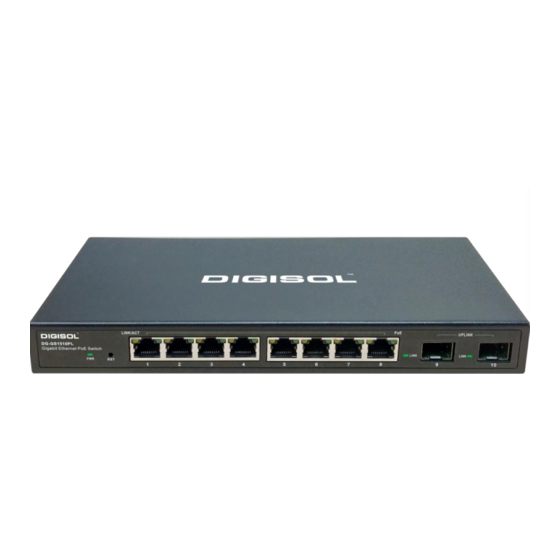
DG-GS1510PL User Manual Products introduction This is a Gigabit Web Managed POE Switch, It provides 8 10/100/1000Mbps Auto-Negotiation RJ45 POE ports and 2 Gigabit SFP Ports . It supports the port's full line speed forwarding to ensure the stable transmission of data. -
Page 7: Hardware Installation
DG-GS1510PL User Manual Hardware installation This chapter provides unpacking and installation information for the Managed PoE switch. First step: open a seal Open the shipping carton and carefully unpack its contents. Please consult the packing list located in the User Manual to make sure all items are present and undamaged. -
Page 8: Rack Installation
DG-GS1510PL User Manual Rack Installation attach the mounting brackets in to the switch's side panels (one on each side) and secure them with the screws provided (please note that these brackets are not designed for palm size switches). Third step: Connecting power supply Using the AC power cord to connect to the power adapter, and then plug in output terminal of the adapter into the DC IN socket on the back of the switch. -
Page 9: Getting Started
DG-GS1510PL User Manual 3 Getting Started This chapter introduces the management interface of Managed PoE switch. Management Option The Managed PoE switch can be managed through any port on the device by using the Web-based management. Each switch must be assigned its own IP address, which is used for communication with Web-Based Management or a SNMP network manager. -
Page 10: Login Web-Based Management
DG-GS1510PL User Manual Login Web-based Management In order to login and configure the switch via an Ethernet connection, the PC must have an IP address in the same subnet as the switch. For example, if the switch has an IP address of 192.168.0.1, the PC should have an IP address of 192.168.0.x (where x is a number between 1 ~ 254), and a subnet mask of 255.255.255.0 Open... -
Page 11: Web
DG-GS1510PL User Manual WEB page Introduction 1. Logon Dialog Box When the following logon dialog box appears, enter the password then click OK. By default, the username is admin and the password is admin. Figure 1 WEB browsing session of the login page Figure 1 shows the login dialog box, the logon dialog box will be displayed while the user enters the web page at the first time.(default IP address is 192.168.0.1/24). -
Page 12: Page Button Introduction
DG-GS1510PL User Manual 2. Page button Introduction On the pages, here are Some commonly used button, the role of these buttons are generally the same, Form 2 on the role of these buttons are described: Form 2: Apply On clicking apply the numerical value will be updated in the memory. As the error-checking is implemented by the web server, before the user selects the button there will be no error checking. -
Page 13: Status Field
DG-GS1510PL User Manual Figure 2: web page of entry field 4. Status Field As shown in Fig. 3 the state field is in the extreme right corner which displays the line status. Since all row state changes are processed in-house, so the status field is read-only. Once the information is filed it will automatically go to active state and the the status will be active. -
Page 14: Main Page
DG-GS1510PL User Manual 5. Main Page Figure 4 shows the WEB main page of the Switch. This page will be displayed after the user logs in web pages Figure 4: Switch switches main page System Configuration: (1)Basic information page Figure 5 is the basic configuration page, users can configure the basic information for the switch. - Page 15 DG-GS1510PL User Manual Figure 5 basic information page (2)Serial port information page Figure6 is a serial port configuration page, this page displays serial baud rate and other related information. When the host,through the serial port terminals (such as Windows, Hyper Terminal),connects to switches then COM port configuration must be consistent with this page information.
- Page 16 DG-GS1510PL User Manual (3)User management page Figure 7 is a user management page, the user can modify this switch anonymous user’s (admin) password. Both Telnet, console use the same anonymous user's password. Passwords are case-sensitive, and can be up to 16 characters. If you want to change your password, the user needs to enter the new...
- Page 17 DG-GS1510PL User Manual Figure 8: Security management page (5)Configure the current page Figure 9 is the current configuration page. the user can view the current configuration of the switch on this page. Save button is to store the current system configuration in the configuration file. Because the storage operation requires erasing &...
- Page 18 PC. Click Upload button to upload a configuration file or image file, configuration file extension must be *. cfg, image file must be provided by DIGISOL and the file name extension must be *. img. Before the system automatically returns to the results page, please do not click on other pages, or restart the switch;...
- Page 19 DG-GS1510PL User Manual Figure11 File Upload Page (8)System reset page Figure 12. is system reset page. Through this page, users can restart the switch. When you click on Restart button, it will pop up a dialog box that prompts the user to determine whether to restart the switch.
-
Page 20: Port Configuration
DG-GS1510PL User Manual Port Configuration (1)Port configuration / port -display page Figure 13 is the port configuration page. Users can enable or disable the port, set the port speed, or View basic information of all ports. To set a specific port, users need to select the appropriate port name from port drop-down menu,. - Page 21 DG-GS1510PL User Manual Figure 14 Port Statistics Page 3)Flow control page Figure 15 is the flow control page. Users can enable and disable each port’s send and receive flow control through this page. Figure 15 Flow control page Page 20...
- Page 22 DG-GS1510PL User Manual 4)Broadcast storm control page Figure 16 is the Broadcast Storm Control page. This page is used to do the suppression for configure port broadcast packets, multicast packets and DLF packet. Figure 16 Broadcast Storm control Page (5)Port speed limits page Figure 17 is the port speed- limit page.
- Page 23 DG-GS1510PL User Manual Figure 17 Port speed limit page (6)Port protection page Figure 18 is the Port protection page. This page is used to configure the port for the protection port. If the port is configured as a protected port, the ports cannot exchange data with other Protected port.
- Page 24 DG-GS1510PL User Manual Port Learning restrict page (1) Figure 19 is the port learning restrict page. This page is used to restrict the number of MAC addresses a port can learn. The range is 0-8191. The default value is 8191, also is the maximum that the port is not configured the restrict learning.
- Page 25 DG-GS1510PL User Manual To create or modify the port trunking, the user need to select a port trunking ID, port trunking ID from 1 to 3. The user clicks the list box the appropriate port trunking ID, the port trunking of information is displayed in the group port.
- Page 26 DG-GS1510PL User Manual (9)Port mirroring configuration page Figure 21 is the port mirroring configuration page. This page allows users to configure port mirroring. Port mirroring through the mirror port is used to monitor the data packets of port. Mirroring Port can only choose one, being mirrored output port and being mirrored(monitor port) port can select multiple.
-
Page 27: Mac Binding
DG-GS1510PL User Manual MAC binding (1)MAC binding configuration page Figure 22 is the MAC binding configuration page. This page is used to achieve the port and MAC address binding. MAC entries on the page is used to enter the MAC address binding, VLAN ID entry is used to enter... -
Page 28: Mac Filtering
DG-GS1510PL User Manual Figure 23 the MAC binding automatic conversion page MAC filtering (1)MAC filtering configuration page Figure 24 is the MAC filtering configuration page. This page is used to configure MAC address filtering on the ports. MAC entries on the page is used to enter the MAC address filtering, VLAN ID entry is used to enter the MAC address affiliated VLAN. - Page 29 DG-GS1510PL User Manual Figure 24 the MAC filtering configuration page (2)MAC filtering automatic conversion page Figure 25 is the MAC filtering automatic conversion page. This page is used to achieve the port MAC address auto-binding. Figure 25 the MAC filtering automatic conversion page...
-
Page 30: Vlan Configuration
DG-GS1510PL User Manual VLAN Configuration (1)VLAN information page Figure 26 shows the current VLAN information page. This page is read-only page displays the current VLAN configuration information, including the VID, state and port members. Select VLAN from the drop-down VID, shows the port information of the Port VLAN members. - Page 31 DG-GS1510PL User Manual (2)Static VLAN configuration page Figure 27 is the static VLAN configuration page that allows users to create VLAN. If you want to create a new VLAN, enter VID on activity line, ranging from 2 to 4094. VLAN name is generated depend on VLAN ID and can not be modified.
- Page 32 DG-GS1510PL User Manual 3)VLAN port configuration page Figure 28 is a VLAN port configuration page, which is used to configure the VLAN port configuration and display results. This page mainly consists of eight parts: port, mode, all current VLAN, port-owned VLAN, key "default VLAN =>"," tagged =>"," untagged =>" and "non-members" =. "...
-
Page 33: Snmp Configuration
DG-GS1510PL User Manual SNMP Configuration (1)SNMP share body configuration page Figure 29 is a shared body of SNMP configuration page that allows users to configure the switch common body name and read and write access, A total of 8 entries can be configured By default, the switch there is a share name as public, the common body is read-only access. -
Page 34: Acl Configuraion
DG-GS1510PL User Manual Figure 30 the TRAP target configuration page ACL Configuration (1)IP Standard ACL configuration page Figure 31 is the IP standard ACL configuration page. Users build ACL standard IP access list using this page. . User can select a ACL group number, in the group to create one or more rules. A rule can match only the source IP address field (with mask). - Page 35 DG-GS1510PL User Manual The addressing method used wild-mask. If the rule were to match the IP address range 192.168.0.0 to 192.168.0.255, then the IP address can be 192.168.0.1, and its mask of 0.0.0.255. Users to configure the rules, each rule must have a filter mode: allow or deny.
- Page 36 DG-GS1510PL User Manual (3)MAC IP ACL configuration page Figure 33 is the MAC IP ACL configuration page. IP MAC group can be the IP packet source and destination MAC address and source and destination IP address control. Figure 33 : the MAC IP ACL configuration page.
- Page 37 DG-GS1510PL User Manual Figure 34 the IP Extended ACL configuration page (5)ACL information page .Figure 35 is the ACL information page, which displays the current ACL rules configured in all the information. Figure 35 is the ACL information page Page 36...
-
Page 38: Qos Configuration
DG-GS1510PL User Manual QoS Configuration (1)QoS Apply Configuration Page Figure 36 is a QoS Apply configuration page. Figure 36 QoS Apply configuration page (2)QoS Schedule Configuration Page Figure 37 is a QoS Schedule configuration page. Page 37... -
Page 39: Ip Basic Configuration
DG-GS1510PL User Manual Figure 37 QoS Schedule configuration page IP Basic Configuration (1)VLAN Interface Configuration Page Figure 38 is a VLAN interface configuration page. Users can configure the VLAN interface through this page, delete VLAN interfaces, configure the interface IP address, remove the interface IP address, and view interface information. - Page 40 DG-GS1510PL User Manual Switch,by default, has a VLAN1 interface, the interface can not be deleted. One can only configure a VLAN interface in this switch. (2)ARP configuration and display page Figure 39 is the ARP configuration and displays all of the information of the ARP table. Users can configure a static ARP entries on this page, delete ARP entries, and revise the dynamic ARP table entry to a static ARP table entry.
-
Page 41: Certification. Authorization. Accounting (Aaa) Configuration
DG-GS1510PL User Manual (3)Host Static Routing configuration page Figure 40 is the static route configuration page, the user can use this page to add, delete static routes. Figure 40 the host static route configuration page 10. Certification. Authorization. Accounting (AAA) configuration (1)Radius Configuration Page... - Page 42 DG-GS1510PL User Manual vendor-specific information, the users typically do not need to modify this field. NAS ports, NAS port type, NAS type of service, these three values do not change in general. Whether to on or off the roaming feature of Radius.
- Page 43 DG-GS1510PL User Manual Server timeout timer, users typically do not need to modify this field. 8.Supplicant timeout timer, users typically do not need to modify this field. 9. Max Request number, users generally do not need to modify this field.
- Page 44 DG-GS1510PL User Manual Figure 43 the 802.1x port configuration page Doing 802.1x authentication, port access, the default maximum host number is 100, the user can modify this field, the biggest support to the 100. (4) 802.1x user authentication information page Figure 44 is a 802.1x user authentication information page, the user can see through this page, all users...
-
Page 45: Spanning Tree Protocol Configuration
DG-GS1510PL User Manual Figure 44 802.1x user authentication information page 11. Spanning Tree Protocol configuration (1) MSTP global configuration page Figure 45 is the MSTP global configuration page, through this page you can configure some MSTP related information, mainly including: Whether to enable MSTP. - Page 46 DG-GS1510PL User Manual Configure the number of hops specified before a BPDU is dropped in a domain. Start or shut down and Cisco compatible spanning tree protocol. Figure 45 MSTP Global Configuration Page (2) MSTP port configuration page Figure 46 is the MSTP global configuration page.
- Page 47 DG-GS1510PL User Manual Configure the cist path cost. Range 1-200000000. The default is 20000000. Lower path costs are more likely to be roots. Configure the type of protocol packets to be sent. Figure 46 MSTP Port Configuration Page...
-
Page 48: Igmp Snooping Configuration
DG-GS1510PL User Manual (3) MSTP configuration information page Figure 47 is the MSTP configuration information page, in this page you can view some MSTP related information Figure 47 MSTP Configuration Information page 12. IGMP SNOOPING configuration (1) IGMP SNOOPING configuration page Figure 48 is the IGMP SNOOPING configuration page, this page you can start IGMP SNOOPING. - Page 49 DG-GS1510PL User Manual Figure 48 IGMP SNOOPING configuration page (2) IGMP SNOOPING information page Figure 49 is the IGMP SNOOPING information page, which allows users to view some information about IGMP SNOOPING. Figure 49 IGMP SNOOPING Information page Page 48...
-
Page 50: Gmrp Configuration
DG-GS1510PL User Manual 13. GMRP configuration (1) GMRP Global Configuration Page Figure 50 shows the GMRP global configuration page. Users can enable GMRP through this page. Figure 50 GMRP Global Configuration Page (2) GMRP port configuration page Figure 51 shows the GMRP port configuration page. You can use this page to enable the GMRP port and view the port information. - Page 51 DG-GS1510PL User Manual Figure 51 GMRP Port Configuration Page (3) GMRP state machine page Figure 52 is the GMRP state machine page. Users can view the GMRP state machine information through this page. Figure 52 is the GMRP state machine page...
-
Page 52: Eaps Configuration
DG-GS1510PL User Manual 14. EAPS configuration (1) EAPS configuration page Figure 53 is an EAPS configuration page, through this page you can configure some EAPS related information, including: Select an EAPS ring number. Configure the operating node mode of an EAPS Domain. -
Page 53: 15、Rmon Configuration
DG-GS1510PL User Manual (2) EAPS information page Figure 54 is an EAPS information page, users can view some EAPS related information. Figure 54 EAPS information page 15、RMON configuration (1) RMON statistics group configuration page Figure 55 shows the RMON statistics group configuration page. You can use this page to configure the RMON statistics group. - Page 54 DG-GS1510PL User Manual Figure 55 RMON statistics group configuration page (2) RMON history group configuration page Figure 56 shows the RMON history group configuration page. You can configure the RMON history group through this page. Select a port from the drop-down list to view/configure the RMON history group configuration for this port.
-
Page 55: 16、Cluster Configuration
DG-GS1510PL User Manual (3) RMON alarm group configuration page Figure 57 shows the RMON alarm group configuration page. You can use this page to create or modify RMON alarm group. Select a configured alarm group from the drop-down list to view/configure its information. - Page 56 DG-GS1510PL User Manual Figure 58 NDP configuration page (2) NTDP configuration page Figure 59 shows the NTDP configuration page. Using this page to configure NTDP. The information that can be set includes: selecting the port, enabling the NTDP function of the port, enabling the global NTDP function, the range of the topology collection, the time interval of collecting the regular topology, the delay time of the first port forwarding the packet, and the forwarding of the packet by other ports.
- Page 57 DG-GS1510PL User Manual Figure 59 NTDP configuration page (3) Cluster Configuration Page Figure 60 is the cluster configuration page. Users can configure the cluster and view the cluster member table through this page. The information that can be set includes: enabling the cluster function, configuring the management VLAN, the address pool of the cluster, the interval for sending handshake packets, the effective retention time of the device, the name of the cluster, the way to join the cluster, and deleting the cluster.
-
Page 58: 17、Log Management
DG-GS1510PL User Manual Figure 50 Cluster Configuration Page 、17. log management (1) Log information page Figure 61 is the Log information page. Users can enable and view various log information through this page. Figure 61 Log Information Page Page 57... -
Page 59: 18、Poe Port Configuration
DG-GS1510PL User Manual Critical: output critical level information. Debugging: Outputs debug level debugging information. Informational: Output information information level debugging information. Warning: output warning level debugging information. ALL: output all log information 18. PoE port Configuration Page Figure 62 is the PoE port configuration / PoE-display page. Users can enable or disable the port's PoE function to the page, or View all ports of PoE information. - Page 60 DG-GS1510PL User Manual Page 59...
Need help?
Do you have a question about the DG-GS1510PL and is the answer not in the manual?
Questions and answers
Digisol Model: DG-GS1510PL 8 port Giga Web Managed PoE Switch with 2 Gigabit SFP Ports How to give static ip address please helo.
To assign a static IP address to the Digisol DG-GS1510PL switch:
1. Connect your PC to the switch using an Ethernet cable.
2. Set your PC's IP address to be in the same subnet as the switch. For example:
- IP address: 192.168.0.x (x = any number from 2 to 254)
- Subnet mask: 255.255.255.0
3. Open a web browser and enter the switch's default IP address: 192.168.0.1.
4. When the login dialog appears, enter:
- Username: admin
- Password: admin
5. After logging in, navigate to the IP configuration section (not explicitly shown in the document, but typically found under "System" or "Network" settings).
6. Enter the desired static IP address and subnet mask.
7. Save the settings and reboot the switch if required.
This answer is automatically generated