Koden GTD-120 Operation Manual
Hide thumbs
Also See for GTD-120:
- Quick start manual (2 pages) ,
- Quick start manual (3 pages) ,
- Quick reference (2 pages)
Table of Contents
Advertisement
Quick Links
Advertisement
Table of Contents

Subscribe to Our Youtube Channel
Related Manuals for Koden GTD-120


Summary of Contents for Koden GTD-120
- Page 5 No part of this publication may be reproduced, transmitted, translated in any from by any means without the written permission of Koden Electronics Co., Ltd. The technical descriptions contained in this publication are subject to change without notice. Koden assumes no responsibility for any errors, incidentals or consequential damages caused by misinterpretation of the descriptions contained in this publication.
-
Page 6: Important Notice
Koden is not liable for damages of accompaniment (change/loss of memorized content, loss of business profit, stop of business) arisen from use or failure of our products. If the stored data are changed or lost, irrespective of causes of troubles and damages, Koden is not liable for them. ... -
Page 7: For Your Safe Operation
GTD-120 For Your safe Operation For Your Safe Operation Symbol used in this Operation Manual The following pictograms are used in this manual. The meaning of each symbols shall be well understood and the maintenance and inspection shall be carried out. - Page 8 For Your Safe Operation GTD-120 Caution on location of equipment Do not install the equipment where it is excessively damp and suffers from excessive water drops. Escaping from static electricity The static electricity may be generated from the carpet on the floor in the cabin or clothes made of synthetic fiber.
-
Page 9: Table Of Contents
GTD-120 Contents Contents Important Notice ........................... ii For Your Safe Operation ........................iii Contents ............................... v Introduction ............................xii System Configuration ........................xiii Configuration of Equipment ....................... xiv Chapter 1 Basic Operation ..................1-1 To use keys ........................... 1-1 How to insert / remove SD card .................... 1-2 Insert SD card .......................... - Page 10 Contents GTD-120 Bird view screen ........................2-1 2 screen display ........................2-2 Operate the cursor ........................ 2-2 Move the chart ........................2-3 Zoom in / out the chart ......................2-3 Cursor OFF ..........................2-3 Cursor ON ..........................2-3 Set the scale for [SCL 1], [SCL 2] and [SCL 3] ................2-3 Measure the distance and bearing between two points ............
- Page 11 GTD-120 Contents Change the color of own ship's track with water depth range ........... 4-6 Change the type of own ship’s track line ................4-7 Setting the number of recording points and recording interval of own ship's track ....4-7 Set the number of record points of own ship's track ..............
- Page 12 Contents GTD-120 Setting the route navigation mode ..................6-11 Active ............................6-11 ............................6-12 Delete the route ........................6-13 Select with the cursor to delete the route ................. 6-13 Select from the list to delete the route ..................6-14 6.10 Move the waypoint of the created route ................
- Page 13 GTD-120 Contents Fine adjustment the diamond drawing ..................7-31 Chapter 8 Alarm .......................8-1 Displaying / not displaying the alarm zone ................8-1 Setting arrival alarm ......................8-2 Setting POB alarm ........................ 8-2 Setting XTE alarm ......................... 8-3 Setting CPA/TCPA alarm ....................... 8-3 Setting speed alarm ......................
- Page 14 Contents GTD-120 Land ............................13-3 Depth ............................13-4 13.2 Display menu ........................13-5 Screen display 1 ........................13-5 Screen display 2 ........................13-8 Set position indication ......................13-11 Set additional information display................... 13-14 Display water temperature / water depth graph ..............13-21 13.3...
- Page 15 GTD-120 Contents DC power cable connection (CW-259-2M) ................16-8 Connection the GPS sensor ....................16-8 Connection with navigation equipment (J1, J2, J3, J4) ............16-9 Connection with AIS receiver (J6) (Prepared by a customer) ..........16-9 Connection of external buzzer and external monitor (J8) (Prepared by a customer) .... 16-10 Connection of remote controller (RCW-15) (J9) (Option) ............
-
Page 16: Introduction
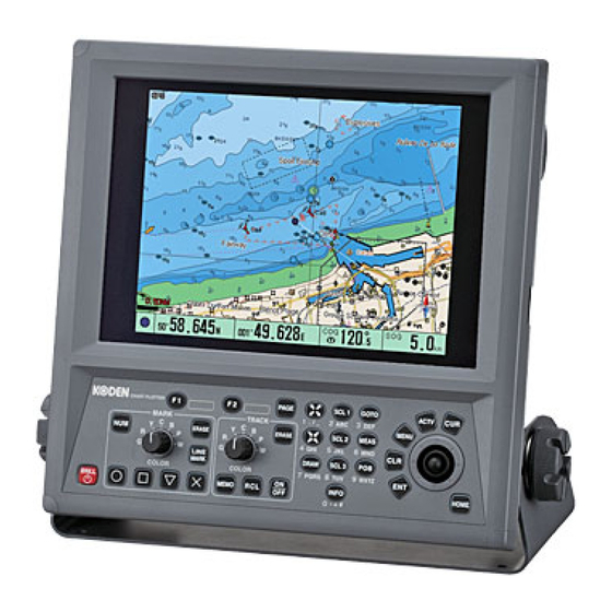
Introduction GTD-120 Introduction GTD-120 is a high-performance GPS plotter with many useful functions. Main features of GTD-120 are as follows. Dual range map, ability to display two different ranges on one screen. Available Bird view display. Equipped with AIS display function . -
Page 17: System Configuration
GTD-120 System Configuration System Configuration Connection diagram Legend Standard Option Owner supplied sensor Remote controller Navigation equipment Echo sounder Radar Autopilot Sonar External monitor (VGA) External buzzer Display unit POWER GTD-120 10.8 to 31.2VDC 0093101202-01 xiii... -
Page 18: Configuration Of Equipment
Configuration of Equipment GTD-120 Configuration of Equipment Standard equipment configuration list Weight/ Name of item Type Remarks Quantity Length Display unit GTD-120 With mounting 8.0 kg bracket and knobs Hard cover A30MB10250 390g DC power cable CW-259-2M With 3-pin water... - Page 19 GTD-120 Configuration of Equipment Optional List Item Name Type Remarks Weight/ Length For GPS position fixing with GPS sensor GPS-20A-10M-B 0.6kg/10m power & signal cable connector [KODEN] GPS compass KGC-222 With Display unit and GPS Antenna Remote controller RCW-15 With 5m cable, (Assembled the...
- Page 20 - This page intentionally left blank.-...
-
Page 21: Chapter 1 Basic Operation
GTD-120 Chapter1 Basic Operation Chapter 1 Basic Operation To use keys 14 15 16 18 19 20 9 10 11 11. [ENT] 21. [ ], [ 1. [BRILL ] Press: Power ON Confirm setting value etc. Chart zoom In / Out Adjust brightness of 12. -
Page 22: How To Insert / Remove Sd Card
GTD-120 How to insert / remove SD card GTD-120 can display C-MAP chart of SD card. C-MAP chart card is owner supplied. In addition, store data such as marks and track by using a commercially available SD card. When using the SD card for the first time, be sure to initialize it with this unit. For the procedure to initialize, refer to "Chapter 12 Save to SD card and import from SD card to Display unit, 12.1... -
Page 23: Power On/Off
GTD-120 Chapter1 Basic Operation Power ON/OFF Power ON 1. Press [BRILL ] key. After power on, the screen switches in the following order. Now Loading GTD-120 Initial screen Warning screen Data loading screen Normal screen 2. While the "Warning screen" is displayed, press [ENT] key. (After “By pressing <ENT key>”... -
Page 24: Select Screen
Chapter1 Basic Operation GTD-120 Select screen There are 5 different displays that can be selected. Each time [PAGE] key is pressed, different display will be brought up. By factory default 3 displays are setup which are outlined below with a thicker line. -
Page 25: Switch Display Screens
GTD-120 Chapter1 Basic Operation Switch display screens 1. Each time [PAGE] key is pressed, the screen changes. (The figure below shows how to change the display screen when shipped from the factory.) Plotter screen Plotter screen Plotter screen Bird view screen Register the display screen You can edit registration of the display modes to different ones. -
Page 26: Overview Of Menu Operation
Chapter1 Basic Operation GTD-120 2. Use joystick [ ↑ ] [ ↓ ] to select the screen to be deleted from [REGIST]. Use joystick [←], and move the cursor to [DELETE]. 3. Press [ENT] key, delete the screen selected in [LAYOUT]. - Page 27 GTD-120 Chapter1 Basic Operation Selection cursor (red frame) 3. Use joystick [ ↑ ] [ ↓ ] to select sub item. 4. Use joystick [←] [→] and select the setting value with the selection cursor (red frame). If the setting value is 4 or more items, the following operations are performed.
-
Page 28: Entering A Numerical Value
Chapter1 Basic Operation GTD-120 Entering a numerical value The selected number turns red. 1) Use joystick [←] [→], specify the digit from which the numerical value is to be changed. (2) Use joystick [ ↑ ] [ ↓ ] to change the value. - Page 29 GTD-120 Chapter1 Basic Operation List of assignment of each key when entering characters Numeric Alphabet Symbol . / _ - : ; A B C a b c D E F d e f G H I g h i...
-
Page 30: Use [Actv] Key
Chapter1 Basic Operation GTD-120 Use [ACTV] key On the 2 screen display, press the [ACTV] key, and the effective screen changes. The screen with the red frame is effective screen, so you can change the scale, operate the cursor, etc. in the effective screen. -
Page 31: [F1] And [F2] Keys Setting Items
GTD-120 Chapter1 Basic Operation 4. Press [MENU] key several times to close the menu. [F1] and [F2] keys setting items Item Function content Stabilization Set the speed display stability. 1: Response is slow 2: Response is between 1 and 3 3: Response is fast *When moving at low speed, setting "1"... -
Page 32: Marking The Pob (Person Over Board) Location
Chapter1 Basic Operation GTD-120 Temp/Dpt Water depth graph or Water temperature graph ON / OFF. Graph Dpt: The water depth graph is ON. Temp: Water temperature graph is ON. Both: The water depth graph and water temperature graph are ON. -
Page 33: Canceling The Pob
GTD-120 Chapter1 Basic Operation Canceling the POB 1. Press [POB] key. [POB operation] window is displayed. 2. Press [CLR] key. POB is canceled, POB information is hide. 1.11 Use [INFO] key Press [INFO] key to display the following information. • Information on objects shown on the chart. -
Page 34: Photograph Display
Chapter1 Basic Operation GTD-120 Photograph display In the items of OBJECT INFORMATION, photographs are included in the MULTIMEDIA CONTENT and PORT/MARINA section. In this case, the color of the items which can display photographs is mint green. Press the [ENT] key after the mint green item has been highlighted. -
Page 35: Ais Information
GTD-120 Chapter1 Basic Operation AIS information Built-in AIS interface board, display other ship information by connecting the AIS receiver. Each time [ACTV] key is pressed, it switches to [Receive Order], [Ship Name Ascending Order], [Ship Name Descending], [Ship Name Descending], [Distance Ascending Order], [CPA Ascending Order], and [TCP Ascending Order]. -
Page 36: 1.12 Nearest Port Info
Chapter1 Basic Operation GTD-120 1.12 Nearest port info Display information close to own ship’s position or the cursor position. 1. Press [MENU] key to display the menu screen. Use joystick [ ↑ ] [ ↓ ] to select [PORT INFO], and use joystick [→]. - Page 37 GTD-120 Chapter1 Basic Operation 4. Use joystick [ ↑ ] [ ↓ ] to select item. 5. Press [ENT] key. Detailed information on the item is displayed. 6. Press [ENT] key. [Nearest port info] screen is not displayed, and the cursor position jumps to place of the target item on the map.
- Page 38 - This page intentionally left blank.-...
-
Page 39: Chapter 2 Plotter Display
GTD-120 Chapter 2 Plotter display Chapter 2 Plotter display Plotter screen On the plotter screen, coastlines, track lines, marks, etc. are displayed. Positioning mode Mark Own ship’s mark Compass icon Own track Number of Scale tracking points Own ship position window Bird view screen Bird view screen is an elevated view of an object from above. -
Page 40: Screen Display
Chapter 2 Plotter display GTD-120 2 screen display You can choose two different scales at the same time by setting the plotter screen side by side. Operate the cursor 1. Press [CUR] key. The cursor and cursor position window are displayed on the screen. Each time [CUR] key is pressed, display switches ON / OFF. -
Page 41: Move The Chart
GTD-120 Chapter 2 Plotter display 2. Use a joystick. The cursor moves in the direction operated the joystick. 3. While cursor is displayed, press [CUR] key, and the cursor will switch ON / OFF. For the operation of cursor OFF, refer to "Chapter 13 How to use the menu, 13.3 SYS/ ALM menu, System 3 for each menu item, CURSOR OFF". -
Page 42: Measure The Distance And Bearing Between Two Points
Chapter 2 Plotter display GTD-120 Measure the distance and bearing between two points You can measure the distance and bearing between any two points. There are 3 methods of measurement: [CURSOR POS], [2 POINTS], [DIST/BRG]. CURSOR POS This method is to measure a distance and a bearing between a base point and an end point with the cursor. -
Page 43: Points
GTD-120 Chapter 2 Plotter display 2 POINTS This method is to measure the distance and bearing between a base point and an end point with numerical values of a latitude and a longitude. 1. Press [CUR] key to set to cursor OFF. -
Page 44: Dist/Brg
Chapter 2 Plotter display GTD-120 DIST/BRG This method is to measure the latitude and longitude between a base point and an end point with a distance and a bearing. 1. Press [CUR] key to set to cursor OFF. 2. Press [MEAS] key. -
Page 45: Display Floating Vrm
GTD-120 Chapter 2 Plotter display Display floating VRM Display a floating Variable Measuring Marker (floating VRM) at any position on the chart. It is convenient to use for distance measurement between any two points and display of entry prohibited area. - Page 46 - This page intentionally left blank.-...
-
Page 47: Chapter 3 Mark
GTD-120 Chapter 3 Mark Chapter 3 Mark You can put marks on fish schools, fish reefs, shallows and fishing points found by fish finder. The shape of the mark can be selected arbitrarily. In addition, you can choose a mark color from 7 colors. -
Page 48: Enter A Marked Line
Chapter 3 Mark GTD-120 • Enter a mark by entering the latitude and longitude numerically 1. Press [NUM] key to display the [Mark store] window. 2. Use joystick [ ↑ ] [ ↓ ] to select [Shape]. 3. Use joystick [←] [→] to select the shape of mark. -
Page 49: Change Line Style Of Marked Line
GTD-120 Chapter 3 Mark Change line style of marked line 1. Press [MENU] key to display the menu screen. Use joystick [ ↑ ] [ ↓ ] to select [SYS/ALM], and use joystick [→]. Use joystick [ ↑ ] [ ↓ ] to select [SYSTEM3], and use joystick [→]. -
Page 50: Event Temporary Store (Ev)
Chapter 3 Mark GTD-120 8. Press [MENU] key several times to close the menu. 15:00 21.3°C Own ship 14:30 20.3°C Track In case, water temperature data is input and the interval is 30 min To display the water temperature, input of water temperature data CAUTION: is necessary. -
Page 51: Set Mark Block To [Ev]
GTD-120 Chapter 3 Mark In using event temporary store, the following settings are necessary. ・Set mark block to [EV] ・Set the mark points ・Set how to switch event display Set mark block to [EV] 1. Press [MENU] key to display the menu screen. -
Page 52: Event Temporary Store Window Operation
Chapter 3 Mark GTD-120 2. Use joystick [ ↑ ] [ ↓ ] to select [EVENT TEMPORARY STORE]. 3. Use joystick [←] [→] to select the mark points. 4. Press [MENU] key several times to close the menu. Set how to switch event display 1. -
Page 53: Change The Color Of Mark
GTD-120 Chapter 3 Mark When press the [CLR] key in the red frame, it will change to a yellow frame, and you can move the map or move the cursor with the joystick operation. Red frame Yellow frame Press [CLR] key When [CLR] key is pressed in the yellow frame, the event temporary store window is OFF. -
Page 54: Erase Mark
Chapter 3 Mark GTD-120 [1] to [4] means [SHAPE SET 1] to [SHAPE SET 4]. 4. Press [MENU] key several times to close the menu. Erase mark There are 3 ways to erase marks as follows. ・Erase a mark by cursor ・Erase a mark by selecting a mark color and shape... -
Page 55: Erase A Mark By Selecting A Mark Color And A Shape
GTD-120 Chapter 3 Mark 6. Press [MENU] key several times to close the menu. Erase a mark by selecting a mark color and a shape 1. Press [CUR] key to cursor OFF. 2. Press [MARK ERASE] key. [MARK ERASE] window is displayed. -
Page 56: Erase A Mark By Selecting A Mark List
Chapter 3 Mark GTD-120 Erase a mark by selecting a mark list 1. Press [MENU] key to display the menu screen. Use joystick [ ↑ ] [ ↓ ] to select [TRK/MRK], and use joystick [→]. Use joystick [ ↑ ] [ ↓ ] to select [DELETE], and use joystick [→]. -
Page 57: Change A Start Block For Recording A Mark
GTD-120 Chapter 3 Mark Change a start block for recording a mark Marks are managed in blocks. The block consists of 7 blocks, MARK BLOCK A to F and EV Block. MARK BLOCKs (A to F) can store 15,000 points per block and EV can store 100 points. You can choose a start block for recording a mark. -
Page 58: Edit Entered Marks
Chapter 3 Mark GTD-120 3.10 Edit entered marks You can edit an enterted mark. Change mark display settings 1. Press [MENU] key to display the menu screen. Use joystick [ ↑ ] [ ↓ ] to select [TRK/MRK], and use joystick [→]. -
Page 59: Change The Color, Shape, Position, Etc. Of The Input Mark
GTD-120 Chapter 3 Mark Change the color, shape, position, etc. of the input mark 1. Press [MENU] key to display the menu screen. Use joystick [ ↑ ] [ ↓ ] to select [TRK/MRK], and use joystick [→]. Use joystick [ ↑ ] [ ↓ ] to select [MRK EDIT], and use joystick [→]. -
Page 60: Transfer The Input Mark To Another Block Etc
Chapter 3 Mark GTD-120 Transfer the input mark to another block etc. 1. Press [MENU] key to display the menu screen. Use joystick [ ↑ ] [ ↓ ] to select [TRK/MRK], and use joystick [→]. Use joystick [ ↑ ] [ ↓ ] to select [TRANSFER], and use joystick [→]. - Page 61 GTD-120 Chapter 3 Mark Event mark transfer. It is used to transfer EV marks (EVent temporary store marks). If there is a mark in the transferred destination, be careful as it will be overwritten and transferred. 4. Use joystick [ ↑ ] [ ↓ ] to select [SOURCE].
- Page 62 - This page intentionally left blank.-...
-
Page 63: Chapter 4 Track
GTD-120 Chapter 4 Track Chapter 4 Track This chapter covers track information, such as display track on the screen, how to store a track, how to change color and select storing interval as well as other useful functions. Record own ship’s track ON / OFF When shipped from factory, it is set to [Track off]. -
Page 64: Record Other Ship's Track
Chapter 4 Track GTD-120 Record other ship’s track You can track a target when the track data is provided from a radar as other ship’s track data. You can display other ship's track of up to 100 targets and set other ship's shape, color, track record number and so on. -
Page 65: Set Track Indication While Track Record Is Interrupted
GTD-120 Chapter 4 Track Set track indication while track record is interrupted When a track record is interrupted, you can set whether own ship's track is displayed on the screen. 1. Press [MENU] key to display the menu screen. Use joystick [ ↑ ] [ ↓ ] to select [TRK/MRK], and use joystick [→]. -
Page 66: Change The Color Of Track
Chapter 4 Track GTD-120 Change the color of track The color of the track can be selected from seven colors: green, red, yellow, cyan, blue, pink and white. Change the color of own ship’s track 1. Turn [Track color] knob to select the color. -
Page 67: Change The Color Of Own Ship's Track With Water Temperature Width
GTD-120 Chapter 4 Track 5. Use joystick [→] to display the [Track color boundary setting] window. G (1) (2) ~14.6°C (1) (Green) color R (3) (4) 14.6°C ~14.8°C (3) (Red) color Y (5) (6) 14.8°C ~15.0°C (5) (Yellow) color C (7) (8) 15.0°C ~15.2°C... -
Page 68: Change The Color Of Own Ship's Track With Water Depth Range
Chapter 4 Track GTD-120 Own ship 10.0 10.2 10.4 10.6 10.8 11.0 11.2 Track [REFERENCE TEMPERATURE]:10.0°C, [CHANGE AMOUNT]: 0.2°C In case 1. Press [MENU] key to display the menu screen. Use joystick [ ↑ ] [ ↓ ] to select [TRK/MRK], and use joystick [→]. -
Page 69: Change The Type Of Own Ship's Track Line
GTD-120 Chapter 4 Track 5. Use joystick [→] to display the [Track color boundary setting] window. G (1) (2) ~20.0m (1) (Green) color R (3) (4) 20.0m~30.0m (3) (Red) color Y (5) (6) 30.0m~40.0m (5) (Yellow) color C (7) (8) 40.0m~50.0m (7) (Cyan) color B (9) (10) 50.0m~60.0m (9) (Blue) color... -
Page 70: Set The Number Of Record Points Of Own Ship's Track
Chapter 4 Track GTD-120 Set the number of record points of own ship's track Own ship's track of record points can be choosen from 6 types of number, 2000 points, 4000 points, 5000 points, 7000 points, 10000 points or 20000 points. -
Page 71: Save Recorded Track
GTD-120 Chapter 4 Track Save recorded track When the track record reaches the recording capacity, overwrite it with a new track in order from the oldest track. If you keep an old track, you must save the track before the track record reaches the recording capacity. -
Page 72: Erase Track
Chapter 4 Track GTD-120 Erase track Erase own ship's track and other ship's track. There are 3 ways to erase the track. • Erase the track by selecting a color • Erase the track by selecting an area • Erase the track automatically at power on startup Erased tracks cannot be undone. - Page 73 GTD-120 Chapter 4 Track 4. Press [ENT] key. [Track erase (area)] window is displayed. 5. Use joystick to decide the end point (second point) of area specification. While moving the cursor, the erase area is indicated by a dotted line.
-
Page 74: Erase The Track Automatically At Power On Start
Chapter 4 Track GTD-120 Erase the track automatically at power on start You can erase the current track and other ship's track automatically when the power is turned on. It is useful to save time to erase when the old track is unnecessary. -
Page 75: Gps Buoy
GTD-120 Chapter 4 Track 4.10 GPS buoy By connecting with the GPS buoy receiver, GPS buoy data can be displayed up to 10 received GPS buoy on the screen. There are 10 memories (100 points per memory) for recording GPS buoy track information. When the GPS buoy's track reaches 100 points, overwrite it with new track in order from the oldest track. -
Page 76: Enable Gps Buoy Function
Chapter 4 Track GTD-120 Enable GPS buoy function By enabling the GPS buoy function, you can use this function. CAUTION: In order to use the GPS buoy function, a corresponding GPS buoy receiver is required. Please contact our dealer or our company for details. -
Page 77: Change The Color Of Gps Buoy
GTD-120 Chapter 4 Track Change the color of GPS buoy The color of the GPS buoy can be selected from 7 colors. The track color of the GPS buoy becomes the same color as the color of the GPS buoy. -
Page 78: Monitor Received Data From Gps Buoy
Chapter 4 Track GTD-120 Monitor received data from GPS buoy 1. Press [MENU] key to display the menu screen. Use joystick [ ↑ ] [ ↓ ] to select [GPS BUOY], and use joystick [→]. Use joystick [ ↑ ] [ ↓ ] to select [MONITOR]. -
Page 79: Delete Gps Buoy Data
GTD-120 Chapter 4 Track Delete GPS buoy data Delete recorded GPS buoy data for each block number. Deleted GPS buoy data cannot be undone. CAUTION: 1. Press [MENU] key to display the menu screen. Use joystick [ ↑ ] [ ↓ ] to select [GPS BUOY], and use joystick [→]. - Page 80 - This page intentionally left blank.-...
-
Page 81: Chapter 5 Waypoint Navigation
GTD-120 Chapter 5 Waypoint Navigation Chapter 5 Waypoint Navigation Waypoint is specific point such as a departure point, a transfer point, and an end point of a voyage. By using waypoint navigation, you can navigate to the point with the shortest distance. -
Page 82: Specify A Mark Number
Chapter 5 Waypoint Navigation GTD-120 4. Press [ENT] key. Waypoint navigation is executed and the waypoint information screen is displayed at the bottom of the screen. Specify a mark number 1. Press [CUR] key to cursor OFF. 2. Press [GOTO] key. -
Page 83: Setting The Cursor Position As The Destination
GTD-120 Chapter 5 Waypoint Navigation Setting the cursor position as the destination Move the cursor to any point and set that point as the waypoint. Also move the cursor to the mark and set the mark as the waypoint. 1. Press [CUR] key to display the cursor. -
Page 84: Setting Own Port As The Waypoint
Chapter 5 Waypoint Navigation GTD-120 Setting own port as the waypoint In order to set own port to waypoint, need to register the location of own port in advance. (Refer to "Chapter 14 Maintenance, 14.6 Regist own port".) 1. Press [CUR] key to cursor OFF. -
Page 85: Resetting The Origin Of The Course Line
GTD-120 Chapter 5 Waypoint Navigation Actual speed Calculate by the actual own ship’s speed data. Constant Calculate by the enterd speed data. 4. Use joystick [ ↑ ] [ ↓ ] to select [Constant]. 5. Use joystick [←] [→] to select ship’s speed. - Page 86 - This page intentionally left blank.-...
-
Page 87: Chapter 6 Route Navigation
GTD-120 Chapter 6 Route Navigation Chapter 6 Route Navigation You can use Route Navigation which is created by connecting each waypoint. Creating routes You can create up to 50 routes and you can register 50 waypoints in one route. Also, you can use marks already entered at the waypoint. -
Page 88: Create A Route By Input The Latitude And Longitude
Chapter 6 Route Navigation GTD-120 4. Move the cursor to the waypoint. 5. Press [ENT] key. Register the waypoint. 6. Repeat steps 4 and 5 to register the waypoint. Position the cursor over the mark and press [ENT] key to register the position of that mark as a waypoint. -
Page 89: Execute Route Navigation
GTD-120 Chapter 6 Route Navigation 3. Use joystick [→]. [Routing (Waypoint registration)] window is displayed. 4. Use joystick and enter the mark number or latitude and longitude to be registered as a waypoint. 5. Press [ENT] key. Register the waypoint. -
Page 90: Select With Cursor And Execute
Chapter 6 Route Navigation GTD-120 Select with cursor and execute 1. Press [MENU] key to display the menu screen. Use joystick [ ↑ ] [ ↓ ] to select [ROUTE], and use joystick [→]. Use joystick [ ↑ ] [ ↓ ] to select [RT EXECUTE], and use joystick [→]. - Page 91 GTD-120 Chapter 6 Route Navigation If the registration order of the waypoints is A → B → C → D, the waypoints in the order of A → B → C → D in the case of forward movement and in the case of backward movement the waypoint is D →...
-
Page 92: Select From The List And Execute
Chapter 6 Route Navigation GTD-120 Select from the list and execute 1. Press [MENU] key to display the menu screen. Use joystick [ ↑ ] [ ↓ ] to select [ROUTE], and use joystick [→]. Use joystick [ ↑ ] [ ↓ ] to select [RT EXECUTE], and use joystick [→]. -
Page 93: Changing The Waypoint Switching During Route Navigation
GTD-120 Chapter 6 Route Navigation If the registration order of the waypoints is A → B → C → D, the waypoints in the order of A → B → C → D in the case of forward movement and in the case of backward movement the waypoint is D →... -
Page 94: Resetting The Starting Point During Route Navigation
Chapter 6 Route Navigation GTD-120 When waypoint is only one and [GOTO] key is pressed, all the waypoints on the route are displayed for remainder, and continues the route navigation to the first waypoint as the new destination. Resetting the starting point during route navigation During route navigation, reset the starting point. - Page 95 GTD-120 Chapter 6 Route Navigation 2. When [DRAW] key is pressed while the [Route operation] window is displayed, [Waypoint movement] window is displayed. 3. Use joystick and move the cursor to the waypoint where you move. 4. Press [GOTO] key.
-
Page 96: Setting The Switching Method Of The Waypoint
Chapter 6 Route Navigation GTD-120 Setting the switching method of the waypoint There are 4 ways to switch the waypoint during route navigation. PERP Waypoint Vertical line Switch the next waypoint after crossing the vertical line intersecting the waypoint on the route. -
Page 97: Setting The Route Navigation Mode
GTD-120 Chapter 6 Route Navigation To change the waypoint, follow the procedure below. 1. Press [MENU] key to display the menu screen. Use joystick [ ↑ ] [ ↓ ] to select [SYS/ALM], and use joystick [→]. Use joystick [ ↑ ] [ ↓ ] to select [SYSTEM1], and use joystick [→]. -
Page 98: Fix
Chapter 6 Route Navigation GTD-120 route that passed through will disappear one after another. After passing through the final waypoint, will end the route navigation. When route navigation is executed, the first waypoint is the starting point position and the second waypoint is the waypoint. -
Page 99: Delete The Route
GTD-120 Chapter 6 Route Navigation Delete the route Deletes registered routes. There are 2 ways to delete the route. • Select with the cursor to delete the route • Select from the list to delete the route CAUTION: Deleted routes cannot be undone. Also, cannot delete routes during route navigation. -
Page 100: Select From The List To Delete The Route
Chapter 6 Route Navigation GTD-120 Select from the list to delete the route 1. Press [MENU] key to display the menu screen. Use joystick [ ↑ ] [ ↓ ] to select [ROUTE], and use joystick [→]. Use joystick [ ↑ ] [ ↓ ] to select [RT DELETE], and use joystick [→]. -
Page 101: Move The Waypoint Of The Created Route
GTD-120 Chapter 6 Route Navigation 6.10 Move the waypoint of the created route Move the waypoint of the created route. There are 2 ways to move the waypoint. • Use the cursor to move the waypoint • Enter the latitude and longitude to move the waypoint Use the cursor to move the waypoint 1. -
Page 102: Enter The Latitude And Longitude To Move The Waypoint
Chapter 6 Route Navigation GTD-120 8. Repeat steps 5 to 7 as necessary to move the waypoint where the movement is necessary. 9. Press [MENU] key several times to close the menu. Enter the latitude and longitude to move the waypoint 1. -
Page 103: Add The Waypoint To The Created Route
GTD-120 Chapter 6 Route Navigation 9. Use joystick to select [POSITION]. 10. Use joystick [→]. Move the cursor to the position setting box. 11. Use joystick to set latitude and longitude. Press [CLR] to return to the original value. 12. Press [ENT] key. -
Page 104: Enter The Latitude And Longitude To Add The Waypoint
Chapter 6 Route Navigation GTD-120 3. Use joystick [→]. [Waypoint addition] window is displayed. 4. Use joystick and move the cursor to the route line between two waypoints. 5. Press [GOTO] key. Display choices for routes near the cursor. If there are multiple routes near the cursor, press [GOTO] key repeatedly to toggle the choices and display the route to add the waypoint. -
Page 105: Delete The Waypoint Of The Created Route
GTD-120 Chapter 6 Route Navigation Press [Zoom out] to display the route list of the next page. Press [Zoom in] to display the route list of the previous page. 4. Use joystick [→]. [Waypoint addition] window is displayed. 5. Use joystick and select [WAYPOINT No]. -
Page 106: Enter The Waypoint Number To Delete The Waypopint
Chapter 6 Route Navigation GTD-120 2. Use joystick [ ↑ ] [ ↓ ] to select [CURSOR]. 3. Use joystick [→]. [Waypoint delete] window is displayed. 4. Use joystick and move the cursor to the waypoint to delete. 5. Press [ENT] key. - Page 107 GTD-120 Chapter 6 Route Navigation 2. Use joystick [ ↑ ] [ ↓ ] to select [LIST]. 3. Use joystick [→]. Use joystick to select the route. Press [Zoom out] to display the route list of the next page. Press [Zoom in] to display the route list of the previous page.
-
Page 108: Edit Comments
Chapter 6 Route Navigation GTD-120 6.13 Edit comments Edit the comment of the created route. 1. Press [MENU] key to display the menu screen. Use joystick [ ↑ ] [ ↓ ] to select [ROUTE], and use joystick [→]. Use joystick [ ↑ ] [ ↓ ] to select [COMMENT], and use joystick [→]. -
Page 109: Chapter 7 Drawing
GTD-120 Chapter 7 Drawing Chapter 7 Drawing You can edit a coastline, prohibited area, etc. in line. In addition, you can also edit parallel line and diamond line. Creating drawings You can create up to 20 blocks drawings and you can register 500 points in one block. - Page 110 Chapter 7 Drawing GTD-120 5. Use joystick and move the cursor to the start point of the line. 6. Press [ENT] key. Register the start point. 7. Use joystick and move the cursor to the next point. Turn [MARK COLOR] knob to change the color of the line.
- Page 111 GTD-120 Chapter 7 Drawing 2. Use joystick [ ↑ ] [ ↓ ] to select [VALUE]. 3. Use joystick [→]. Use joystick [ ↑ ] [ ↓ ] to select the block to store the drawing points. 4. Use joystick [→].
- Page 112 Chapter 7 Drawing GTD-120 Press [CLR] key to cancel the previously created line. After registering A → B → C, press [CLR] key Operation when [CLR] key is pressed Press [CUR] key, registered as the start point. After registering A → B → C,...
- Page 113 GTD-120 Chapter 7 Drawing 2. Use joystick [ ↑ ] [ ↓ ] to select [DRAW FUNCTION]. 3. Use joystick [←] [→] to select [Draw]. 4. Press [MENU] key several times to close the menu. 5. Press [DRAW] key. [Drawing] window is displayed.
-
Page 114: Delete The Drawing
Chapter 7 Drawing GTD-120 Delete the drawing Deletes registered drawing. There are 2 ways to delete the drawing. • Select with the cursor to delete the drawing • Select from the list to delete the drawing Delete every block (500 points). Deleted drawings cannot be undone. -
Page 115: Select From The List To Delete The Drawing
GTD-120 Chapter 7 Drawing Select from the list to delete the drawing 1. Press [MENU] key to display the menu screen. Use joystick [ ↑ ] [ ↓ ] to select [DRAWING], and use joystick [→]. Use joystick [ ↑ ] [ ↓ ] to select [DELETE], and use joystick [→]. -
Page 116: Move The Point Of Created Drawings
Chapter 7 Drawing GTD-120 2. Use joystick [ ↑ ] [ ↓ ] to select the drawing block. 3. Use joystick [→]. [Drawing recall] window is displayed. 4. Use joystick [ ↑ ] [ ↓ ] to select the item, use joystick [←] [→] to change the setting. -
Page 117: Enter The Latitude And Longitude To Move The Point
GTD-120 Chapter 7 Drawing 2. Use joystick [ ↑ ] [ ↓ ] to select [CURSOR]. 3. Use joystick [→]. [Drawing point move] window is displayed. 4. Use joystick and move the cursor to the point to move. 5. Press [GOTO] key. - Page 118 Chapter 7 Drawing GTD-120 2. Use joystick [ ↑ ] [ ↓ ] to select [VALUE]. 3. Use joystick [→]. Use joystick to select the drawing block. Press [Zoom out] to display the drawing list of the next page. Press [Zoom in] to display the drawing list of the previous page.
-
Page 119: Add The Point To The Created Drawing
GTD-120 Chapter 7 Drawing Add the point to the created drawing Add the point for the created drawing. There are 2 ways to add the point. • Use the cursor to add the point • Enter the latitude and longitude to add a point Use the cursor to add the point 1. -
Page 120: Enter The Latitude And Longitude To Add A Point
Chapter 7 Drawing GTD-120 9. Press [MENU] key several times to close the menu. Enter the latitude and longitude to add a point 1. Press [MENU] key to display the menu screen. Use joystick [ ↑ ] [ ↓ ] to select [DRAWING], and use joystick [→]. -
Page 121: Delete The Point Of The Created Drawing
GTD-120 Chapter 7 Drawing 10. Use joystick [→]. Move the cursor to the position setting box. 11. Use joystick to set latitude and longitude. Press [CLR] to return to the original value. 12. Press [ENT] key. Add a new point. -
Page 122: Enter The Point Number To Delete The Point
Chapter 7 Drawing GTD-120 3. Use joystick [→]. [Drawing point delete] window is displayed. 4. Use joystick and move the cursor to the point to delete. 5. Press [ENT] key. Delete the selected point. 6. Repeat steps 4 and 5 as necessary to delete the point. -
Page 123: Edit Comments
GTD-120 Chapter 7 Drawing 4. Use joystick [→]. [Drawing point delete] window is displayed. 5. Use joystick and select [POINT No]. 6. Use joystick [→]. Move the cursor to the setting box of the point number. 7. Use joystick to set [POINT No]. -
Page 124: Enter Comments On Created Drawings
Chapter 7 Drawing GTD-120 2. Use joystick and select the drawing block for editing comments. Press [Zoom out] to display the drawing block of the next page. Press [Zoom in] to display the drawing block of the previous page. 3. Use joystick [→]. -
Page 125: Parallel Drawing
GTD-120 Chapter 7 Drawing 3. Use joystick [←] [→] to select [ON]. 4. Press [MENU] key several times to close the menu. 5. Press [CUR] key to display the cursor. 6. Use joystick and move the cursor to the created drawing. -
Page 126: Register The Parallel Drawing In The [Draw] Key
Chapter 7 Drawing GTD-120 Register the parallel drawing in the [DRAW] key By registering in the [DRAW] key, it becomes possible to perform parallel drawing. Cannot be used with diamond drawing. CAUTION: 1. Press [MENU] key to display the menu screen. -
Page 127: Setting The Drawing Method For Parallel Drawing
GTD-120 Chapter 7 Drawing 3. To erase parallel lines, press [DRAW] key. [Parallel drawing] window is displayed. 4. Press [CLR] key. Erase the parallel lines. Setting the drawing method for parallel drawing There are 3 ways to draw parallel line. -
Page 128: Contents
Chapter 7 Drawing GTD-120 2. Press [INFO] key. [Parallel drawing setting] window is displayed. 3. Use joystick [←] [→] to select [DST/BRG]. 4. Use joystick [ ↑ ] [ ↓ ] to select [BASE POS] or [MARK]. BASE POS Specify the base point position with the latitude and longitude. - Page 129 GTD-120 Chapter 7 Drawing 2 POINTS Draw a parallel line by specifying the base point and end point position. 1. Press [DRAW] key. [Parallel drawing] window is displayed. 2. Press [INFO] key. [Parallel drawing setting] window is displayed. 3. Use joystick [←] [→] to select [2 POINTS].
- Page 130 Chapter 7 Drawing GTD-120 7. Use joystick, enter the end point, and press [ENT] key. 8. Use joystick [ ↓ ] to move the cursor to [LINE INTERVAL]. 9. Use joystick and enter the interval. 10. Use joystick [ ↓ ] to move the cursor to [NUMBER].
- Page 131 GTD-120 Chapter 7 Drawing 2. Press [INFO] key. [Parallel drawing setting] window is displayed. 3. Use joystick [←] [→] to select [COURSE LINE]. 4. Use joystick [ ↓ ] to move the cursor to [LINE INTERVAL]. 5. Use joystick and enter the interval.
-
Page 132: Fine Adjustment The Parallel Drawing
Chapter 7 Drawing GTD-120 Fine adjustment the parallel drawing Fine adjustment the set parallel line. 1. Press [DRAW] key. [Parallel drawing] window is displayed, and display parallel lines on the map. 2. Fine adjustment is possible by the following operation. -
Page 133: Diamond Drawing
GTD-120 Chapter 7 Drawing Press [MEMO] key or [RCL] key With the base point as the origin, the interval narrows. Keep pressed [MEMO] key. Base point Keep pressed With the base point as the [RCL] key. origin, the interval becomes Base point wider. -
Page 134: Register The Diamond Drawing In The [Draw] Key
Chapter 7 Drawing GTD-120 Register the diamond drawing in the [DRAW] key By registering in the [DRAW] key, you can quickly perform diamond drawing function. Cannot be used with parallel drawing. CAUTION: 1. Press [MENU] key to display the menu screen. -
Page 135: Setting The Drawing Method For Diamond Drawing
GTD-120 Chapter 7 Drawing 3. To erase diamond lines, press [DRAW] key. [Diamond drawing] window is displayed. 4. Press [CLR] key. Erase diamond lines. Setting the drawing method for diamond drawing There are 2 ways of diamond drawing. • OS POS •... - Page 136 Chapter 7 Drawing GTD-120 1. Press [DRAW] key. [Diamond drawing] window is displayed. 2. Press [INFO] key. [Diamond drawing setting] window is displayed. 3. Use joystick [←] [→] to select [OS POS]. 4. Use joystick [ ↓ ] to select [LINE BEARING].
- Page 137 GTD-120 Chapter 7 Drawing 12. Use joystick [ ↓ ] to move the cursor to [DIRECTION]. 13. Use joystick [←] [→] to select the direction in which the diamond line is displayed relative to the base line bearing. DIRECTION [LEFT]...
- Page 138 Chapter 7 Drawing GTD-120 2. Press [INFO] key. [Diamond drawing setting] window is displayed. 3. Use joystick [←] [→] to select [CUR POS]. 4. Use joystick [ ↓ ] to select [LINE BEARING]. 5. Use joystick [←] [→] to select [COURSE] or [BEARING].
-
Page 139: Fine Adjustment The Diamond Drawing
GTD-120 Chapter 7 Drawing 14. Press [ENT] key. Display diamond lines with the contents entered. Fine adjustment the diamond drawing Fine adjustment the set diamond line. 1. Press [DRAW] key. [Diamond drawing] window is displayed, and display diamond lines on the map. - Page 140 - This page intentionally left blank.-...
-
Page 141: Chapter 8 Alarm
GTD-120 Chapter 8 Alarm Chapter 8 Alarm There are 7 types of alarm functions such as arrival, POB, XTE, area, drawing, CPA / TCPA and ship speed. When the alarm function is set, an alarm will sound when the alarm condition occurs. -
Page 142: Setting Arrival Alarm
Chapter 8 Alarm GTD-120 Setting arrival alarm Arrival alarm is a function to sound an alarm when own ship enters into the alarm zone of the waypoint. The zone is displayed with a red circle. Range Own ship Alarm zone Waypoint 1. -
Page 143: Setting Xte Alarm
GTD-120 Chapter 8 Alarm 6. Press [MENU] key several times to close the menu. To cancel the POB alarm, set to [OFF] in step 3. CAUTION: Setting XTE alarm XTE (Cross Track Error) alarm is a function to sound an alarm when own ship is away from the course range. -
Page 144: Setting Speed Alarm
Chapter 8 Alarm GTD-120 1. Press [MENU] key to display the menu screen. Use joystick [ ↑ ] [ ↓ ] to select [SYS/ALM], and use joystick [→]. Use joystick [ ↑ ] [ ↓ ] to select [ALARM 1], and use joystick [→]. -
Page 145: Setting Area Alarm
GTD-120 Chapter 8 Alarm 5. Use joystick [←] [→] to select the range. 6. Press [MENU] key several times to close the menu. To cancel the speed alarm, set to [OFF] in step 3. CAUTION: Setting area alarm Area alarm is a function to sound an alarm when own ship enters into the set range. -
Page 146: Set The Area Alarm Range
Chapter 8 Alarm GTD-120 Set the area alarm range 1. Press [MENU] key to display the menu screen. Use joystick [ ↑ ] [ ↓ ] to select [SYS/ALM], and use joystick [→]. Use joystick [ ↑ ] [ ↓ ] to select [ALARM 2], and use joystick [→]. -
Page 147: Setting Drawing Alarm
GTD-120 Chapter 8 Alarm Setting drawing alarm Drawing alarm is a function that will trigger alarm when own ship enters inside the drawn zone. The area alarm can be created as alarm zones using free form. The zone specified in [ALARM RANGE] around the construction line is the range of drawing alarm. -
Page 148: Set The Drawing Alarm Range
Chapter 8 Alarm GTD-120 Set the drawing alarm range 1. Press [MENU] key to display the menu screen. Use joystick [ ↑ ] [ ↓ ] to select [SYS/ALM], and use joystick [→]. Use joystick [ ↑ ] [ ↓ ] to select [ALARM 3], and use joystick [→]. -
Page 149: 8.10 Setting Grounding Alarm
GTD-120 Chapter 8 Alarm 6. Press [MENU] key several times to close the menu. To cancel the depth limit alarm, set to [OFF] in step 3. CAUTION: 8.10 Setting grounding alarm This alarm is activated when the depth value of own ship’s position becomes shallower than the set value. - Page 150 - This page intentionally left blank.-...
-
Page 151: Chapter 9 Ais
GTD-120 Chapter 9 AIS Chapter 9 AIS By connecting to AIS receiver, AIS symbols wil be displayed on the screen. Up to 128 AIS symbols can be displayed. Enable the AIS display function When AIS display is set to [ON], this function is enabled. If this is set to [OFF], this function is disabled. -
Page 152: Setting The Detection Range
Chapter 9 AIS GTD-120 Setting the detection range Set the range to detect (display) the AIS symbol. The ship inside of the the set range from own ship can be displayed and the ship outside of the set range cannot be displayed. -
Page 153: Setting Minimum Detection Speed
GTD-120 Chapter 9 AIS Setting minimum detection speed Set the minimum speed to display AIS symbols. 1. Press [MENU] key to display the menu screen. Use joystick [ ↑ ] [ ↓ ] to select [AIS], and use joystick [→]. -
Page 154: Display On / Off Ship Name
Chapter 9 AIS GTD-120 Display ON / OFF ship name Display the ship name on the AIS symbol. *If there is no ship name data, MMSI number is displayed. *MMSI number: Identification number assigned to each AIS device by maritime mobile service... -
Page 155: Change The Shape Of The Stop Symbol
GTD-120 Chapter 9 AIS 7. After entering the numerical value, use joystick [→] to exit from the numerical value box. 8. Press [MENU] key several times to close the menu. * To NOT display a vector line, select [OFF] in step 3. - Page 156 - This page intentionally left blank.-...
-
Page 157: Chapter 10 Gps/Dgps
GTD-120 Chapter 10 GPS/DGPS Chapter 10 GPS/DGPS Check the setting of GPS / DGPS and the received status of the beacon receiver. 10.1 GPS / DGPS monitor screen The GPS / DGPS monitor screen displays signal status of GPS satellites. -
Page 158: Gps / Dgps Settings
Chapter 10 GPS/DGPS GTD-120 10.2 GPS / DGPS settings Set GPS / DGPS. STABILIZATION Set the speed of response to movement. [3] is the fastest response. *When moving at low speed, the speed display stability may be better when set to [1]. -
Page 159: Chapter 11 Setup I/O Interface
GTD-120 Chapter 11 Setup I/O Interface Chapter 11 Setup I/O Interface In the [I/O] menu, change settings to input / output data. This menu should be set when installed. If incorrect settings are set, there is a possibility that connected devises will not communicate properly. -
Page 160: Set Output Sentence
Chapter 11 Setup I/O Interface GTD-120 Import from J5 Import from J1 Import from J1 4. Press [MENU] key several times to close the menu. CAUTION: If you set the input connector selection to [AUTO], if the sentence from the connector with the highest priority is interrupted, it switches to receiving the sentence from the connector with the next highest priority. -
Page 161: Monitoring Input Sentences
When external output switching is [Standard], cannot switch between [ON] or [OFF]. 5. Press [MENU] key several times to close the menu. [HDT] can be output when HDT sentence has been input in GTD-120. CAUTION: [GTD] can be output when position data is set to [LORAN C]. - Page 162 Chapter 11 Setup I/O Interface GTD-120 2. Use joystick [←] [→] to select the connector number. Monitor the input sentence. If you watch only a specific sentence, do the following operation. 3. Use joystick [ ↑ ] [ ↓ ] to select the sentence.
-
Page 163: Chapter 12 Save To Sd Card And Import From Sd Card To Display Unit
<Compliant standard> SD Memory Card Specification Part1 PHYSICAL LAYER SPECIFICATION Ver 2.0 <Speed class> Class 6 <Command class> Class 10 or more KODEN standard SD card (Refer to “Optional list” page xv) Commercial product recommended SD card Maker Standard ADTEC AD-SDHM4G/6... - Page 164 Chapter 12 Save to SD card and import from SD card to Display unit GTD-120 2. Use joystick [ ↑ ] [ ↓ ] to select [SD CARD INIT]. 3. Use joystick [→]. [SD Card initialize] window is displayed. 4. Press [ENT] key.
-
Page 165: Save Data To Sd Card
GTD-120 Chapter 12 Save to SD card and import from SD card to Display unit 12.2 Save data to SD card Data (MARK, OWN TRACK, DRAW, TARGET TRK, ROUTE, PICTURE and SETTING) can be saved in the SD card. 1. Insert the initialized SD card or the SD card which is saved the existing data into the card slot. - Page 166 Chapter 12 Save to SD card and import from SD card to Display unit GTD-120 7. Use joystick [ ↑ ] [ ↓ ] to select the data to save. Selected [DRAW], [TARGET TRK], [ROUTE] or [PICTURE] in step 5: Press [Zoom out], and [BUILT-IN] setting box of the next page is displayed.
- Page 167 GTD-120 Chapter 12 Save to SD card and import from SD card to Display unit 11. Press [ENT] key. Save the data to the selected number in step 9 and display the date and time. In step 9, select the number that has already been saved, and then press [ENT] key in step 11, the [Overwrite] window will be displayed.
-
Page 168: Save The Data Of The Sd Card To The Internal Memory
Chapter 12 Save to SD card and import from SD card to Display unit GTD-120 12.3 Save the data of the SD card to the internal memory Read the data saved in the SD card and import it into the internal memory of the Display unit. - Page 169 GTD-120 Chapter 12 Save to SD card and import from SD card to Display unit 7. Use joystick [ ↑ ] [ ↓ ] to select the block number to save. Selected [DRAW], [TARGET TRK], [ROUTE] or [PICTURE] in step 5: Press [Zoom out], and [BUILT-IN] setting box of the next page is displayed.
- Page 170 Chapter 12 Save to SD card and import from SD card to Display unit GTD-120 12. Press [ENT] key. Save the data to the selected number in step 7. In step 7, select the number that has already been saved, and then press [ENT] key in step 12, the [Backup] window will be displayed.
-
Page 171: Erase Data In The Sd Card
GTD-120 Chapter 12 Save to SD card and import from SD card to Display unit 12.4 Erase data in the SD card Unnecessary data saved in the SD card can be erased. 1. Insert the SD card which is saved the data into the card slot. - Page 172 Chapter 12 Save to SD card and import from SD card to Display unit GTD-120 7. Use joystick [→] to select the [ERASE]. The [Built-in] setting box is grayed out, and the [Card] setting box shows the data saved in the SD card.
-
Page 173: Backup
GTD-120 Chapter 12 Save to SD card and import from SD card to Display unit 12.5 Backup Backup the internal data of the Display unit (MARK, OWN TRACK, DRAW, TARGET TRK, ROUTE, PICTURE and SETTING) at once. 1. Insert the SD card into the card slot. -
Page 174: Restore
Chapter 12 Save to SD card and import from SD card to Display unit GTD-120 12.6 Restore Restore the back up data (MARK, OWN TRACK, DRAW, TARGET TRK, ROUTE, PICTURE and SETTING) back to the unit all at once. All internal data of the Display unit will be overwritten. -
Page 175: Chapter 13 Menu Operation
GTD-120 Chapter 13 Menu Operation Chapter 13 Menu Operation 13.1 Chart data menu This menu is to set or modify chart data display. Chart for each menu item These settings are about the chart display, MAP COLOR, MIXING LEVELS, BOUND LINES, GRID, VALUE-ADDED DATA, ANTI-CLUTTER and ELEVATION. -
Page 176: Marine
Chapter 13 Menu Operation GTD-120 GRID The Lat/Lon line display ON / OFF. In the Perspective View mode, the depth of the screen is shown in the grid. VALUE-ADDED DATA Value-Added Data (VAD) on the map display ON / OFF. -
Page 177: Land
GTD-120 Chapter 13 Menu Operation LIGHT ANIMATION Displays a lighthouse or buoy as animation effect. Typically this function is used to show the visible lighthouses from the actual ship’s position. Black light: The light of the lighthouse is not visible from the point of observation. -
Page 178: Depth
Chapter 13 Menu Operation GTD-120 LAKE & RIVER Lake or river display ON /OFF. CULTURAL FEATURES Cultural features display ON /OFF. ROADS Roads display ON /OFF. ROAD NAME Road names display ON /OFF. RAILWAY Railways display ON /OFF. -
Page 179: Display Menu
GTD-120 Chapter 13 Menu Operation HIGHLIGHTS RANGE MAX Sets the maximum value for the Highlights Range setting. REVERSE CONTOUR COLOR Reverses the order of the contour coloring. 13.2 Display menu This menu is to make display changes. Screen display 1 These settings are about the screen display;... - Page 180 Chapter 13 Menu Operation GTD-120 COURSE LINE It is a line showing the direction of own ship. Select whether to display (priority of course, both). HEADING When the heading signal is input, the line is indicated to the heading direction in white.
- Page 181 GTD-120 Chapter 13 Menu Operation To change the color of the current direction line, [MAINTENANCE] => [COLOR] => [No.152] on the menu. POSITION MARK Set the shape of own ship mark. NAV SWITCH1 / 2 Set the direction of the upward screen by [NAV SWITCH1] / [NAV SWITCH2].
-
Page 182: Screen Display 2
Chapter 13 Menu Operation GTD-120 CURSOR LINE Select whether a line is connected to own ship and cursor. To change the color of the cursor line, use [MAINTENANCE] => [COLOR] => [No.152] on the menu. WPT LINE Select whether a line is connected to the starting point and the waypoint. - Page 183 GTD-120 Chapter 13 Menu Operation *Can also enter by pressing the numeric keypad. After entering the numerical value, use joystick [→] a few times to exit from the numerical value input box. 4. Press [MENU] key several times to close the menu.
- Page 184 Chapter 13 Menu Operation GTD-120 To change the color of the ring marker, use [MAINTENANCE] => [COLOR] => [No.152] on the menu. VRM Select whether VRM (Variable Range Marker) is displayed around own ship. The VRM size can be changed, so it is convenient when you keep a certain distance from the restricted area etc.
-
Page 185: Set Position Indication
GTD-120 Chapter 13 Menu Operation (3) Data Off Red: When at least one of the following objects or layers is turned off (by the user); Depth*, Attention Areas, Track & Routes, Lighthouse, Buoys, Signals, Light animation, Underwater Objects. (*Depth Range Min setting is more than 20m, or Depth Range Max setting is less than 20m) (4) Declutter Red: When Anti clutter function is ON. - Page 186 Chapter 13 Menu Operation GTD-120 2. Use joystick [←] [→] to select [LAT/LON]. If you need to make corrections, carry out the procedure from step 3. 3. Use joystick [ ↑ ] [ ↓ ] to select [LAT CORRECTION]. Use joystick [→]. The cursor moves to the numerical value input box.
- Page 187 GTD-120 Chapter 13 Menu Operation 2. Use joystick [ ↑ ] [ ↓ ] to select [LORAN C]. 3. Use joystick [ ↑ ] [ ↓ ] to select [GRI]. Use joystick [←] [→] to select GRI code. 4. Use joystick [ ↑ ] [ ↓ ] to select [SLAVE STATION1].
-
Page 188: Set Additional Information Display
Chapter 13 Menu Operation GTD-120 Set additional information display Added Info of POS Add additional information display area to own ship's position window. Added Info of POS area Clock Displays the date, the day of the week, and the current time. - Page 189 GTD-120 Chapter 13 Menu Operation 2. Use joystick [ ↑ ] [ ↓ ] to select [Added Info of POS]. 3. Use joystick [ ↑ ] [ ↓ ] to select [ON]. Add additional information display area to own ship position window.
- Page 190 Chapter 13 Menu Operation GTD-120 Arrival time of WPT The time of arrival at the waypoint, the route number, and the waypoint are displayed. TTG/ETA TTG (Time To Go) and ETA (Estimated Time of Arrival) are displayed. Remaining route The remaining distance in route navitation is displayed.
- Page 191 GTD-120 Chapter 13 Menu Operation Added Info of POB Add additional information display area to the POB window. Added Info of POB area Speed The travel distance from the POB point is displayed as the Average average speed. Can check the drift.
- Page 192 Chapter 13 Menu Operation GTD-120 Added Info of Cursor Add additional information display area to the cursor window. Added Info of cursor area TTG/ETA to Cursor TTG (Time To Go) and ETA (Estimated Time of Arrival) are displayed. 1. Press [MENU] key to display the menu screen.
- Page 193 GTD-120 Chapter 13 Menu Operation Info window1, Info window2 Up to two information windows can be displayed on the upper right of the screen. Lat/Lon The latitude and longitude of own ship's position are displayed. Clock/Water The current time and the water temperature are Temp.
- Page 194 Chapter 13 Menu Operation GTD-120 1. Press [MENU] key to display the menu screen. Use joystick [ ↑ ] [ ↓ ] to select [DISPLAY], and use joystick [→]. Use joystick [ ↑ ] [ ↓ ] to select [ADDED INFO], and use joystick [→].
-
Page 195: Display Water Temperature / Water Depth Graph
GTD-120 Chapter 13 Menu Operation 2. Use joystick [ ↑ ] [ ↓ ] to select [Cursor Window]. 3. Use joystick [←] [→] to select the display information. 4. Press [MENU] key several times to close the menu. To hide the cursor window, select [OFF] in step 3. - Page 196 Chapter 13 Menu Operation GTD-120 2. Use joystick [ ↑ ] [ ↓ ] to select [W.TEMP/DEPTH GRAPH]. 3. Use joystick [←] [→] to select the type of graph. The water depth graph is displayed. Temp The water temperature graph is displayed.
-
Page 197: Sys/Alm Menu
GTD-120 Chapter 13 Menu Operation MANUAL SHIFT Set the start depth of the water depth graph. You operate it when [DEPTH SHIFT] is set to [MAN]. W.TEMP COLOR, DEPTH COLOR Select the color of water temperature graph and water depth graph. - Page 198 Chapter 13 Menu Operation GTD-120 3. Use joystick [←] [→] to change the setting. 4. Press [MENU] key several times to close the menu. L/L ACCURACY Select the display of latitude and longitude from [1/1000 min] or [1/10000 min].
-
Page 199: System 2
GTD-120 Chapter 13 Menu Operation System 2 These settings are about the system; AUTO SCROLL, SCRL DIRECT, POS CORR, TIME CORR, MAG DEVIATION, CORR, HDG DEVIATION, COMPASS CORR, HDG AZIMUTH, FIX SCALE, REQUIRED TIME and CONSTANT. 1. Press [MENU] key to display the menu screen. - Page 200 Chapter 13 Menu Operation GTD-120 POS CORR The coastline position may be slightly different from the actual position. For example, if own ship is in the harbor but it is displayed in different location, such as on land. In this case, correction is required.
-
Page 201: System 3
UTC (Universal standard time). MAG DEVIATION, CORR GTD-120 calculates the bearing in the true bearing. When [COURSE DISP] of [DISPLAY 1] is set to [MAG], it is necessary to correct the magnetic deviation. In GTD-120, all magnetic deviation on the earth is memorized, so you can use [AUTO]. - Page 202 Chapter 13 Menu Operation GTD-120 2. Use joystick [ ↑ ] [ ↓ ] to select the item. 3. Use joystick [←] [→] to change the setting. To enter a numerical value, Use joystick [→] to move the cursor to the numerical value input box.
- Page 203 GTD-120 Chapter 13 Menu Operation LINE MARK STYLE Refer to “Chapter 3 Mark, 3.2 Enter a marked line”, “Change mark shape of marked line” and “Change line style of marked line”. EVENT MARK When a sentence of the external event mark (TLL) is recieved from an external device (Echo sounder, radar, etc.), the point is registered as a mark including the latitude and longitude.
- Page 204 - This page intentionally left blank.-...
-
Page 205: Chapter 14 Maintenance
GTD-120 Chapter 14 Maintenance Chapter 14 Maintenance 14.1 Simulation Using simulation, you can try to operate the plotter without navigation. All keys are available to operate in the same way as normal. 1. Press [MENU] key to display the menu screen. -
Page 206: System Test
14.2 System test This section explains the test items for checking the operation status of GTD-120. There are 7 types of system tests: LCD test, memory test, operation unit test, brightness test, communication test, system information and power supply information. - Page 207 GTD-120 Chapter 14 Maintenance OPE UNIT This test checks whether the key operation of the operation unit is performed normally or whether the buzzer sounds normally. 1. Press [MENU] key to display the menu screen. Use joystick [ ↑ ] [ ↓ ] to select [MAINTENANCE], and use joystick [→].
- Page 208 7. To test with another connector, repeat steps 4 to 6. 8. Press [MENU] key several times to close the menu. SYS INFO System information is a screen to check the version etc. of the modules that make up GTD-120. Version information of boot program. System Version information of system program.
-
Page 209: Color Palette
GTD-120 Chapter 14 Maintenance 14.3 Color palette You can change the item color by color palette. Set 3 primary colors of red, green and blue. 1. Press [MENU] key to display the menu screen. Use joystick [ ↑ ] [ ↓ ] to select [MAINTENANCE], and use joystick [→]. - Page 210 Chapter 14 Maintenance GTD-120 If you press [CLR] key in step 3 (displaying the sub window), the color CAUTION: of the color palette selected in step 2 will return to the factory default color. In step 2, press [INFO] key...
- Page 211 GTD-120 Chapter 14 Maintenance Color palette list Initial Initial Color name Color name BACKGROUND TGT TRK WHITE GREEN HEADING LINE CURRENT DIRECTION LINE YELLOW CURSOR LINE CYAN AIS SYMBOL BLUE WPT DIRECTION LINE PINK BG of OPERATION GUIDE WHITE FLOATING VRM...
-
Page 212: Screen Shot
Screen shot Up to 100 pictures can be stored as screen shots. Stored pictures can be displayed on GTD-120. To store pictures as a bitmap file in the SD card, refer to “Chapter 12 Save to SD card and import from SD card to Display unit, 12.2 Save data to SD card". -
Page 213: Erase Stored Pictures
GTD-120 Chapter 14 Maintenance Erase stored pictures There are 2 ways to erase stored pictures. • Erase the picture being displayed • Erase the picture of the selected number from stored picture list. CAUTION: Erased pictures can not be recovered. -
Page 214: Memory Erase
4. Press [ENT] key. Erase the picture. 14.5 Memory erase Erase the data saved in the memory of GTD-120. However, it is not possible to undo erased data, so be careful when erasing it. Erase mark Marks can be erased by each block. -
Page 215: Erase Drawing
GTD-120 Chapter 14 Maintenance 2. Use joystick [ ↑ ] [ ↓ ] to select [OWN TRACK]. 3. Use joystick [→]. The cursor move to [TRACK]. 4. Use joystick [ ↑ ] [ ↓ ] to select the block to erase. -
Page 216: Erase Tgt Track
Chapter 14 Maintenance GTD-120 Erase TGT track TGT tracks can be erased by each block. 1. Press [MENU] key to display the menu screen. Use joystick [ ↑ ] [ ↓ ] to select [MAINTENANCE], and use joystick [→]. Use joystick [ ↑ ] [ ↓ ] to select [MEM ERASE], and use joystick [→]. -
Page 217: Erase Picture
GTD-120 Chapter 14 Maintenance 7. Press [ENT] key. Erase the data. 8. Press [MENU] key several times to close the menu. Erase picture Pictures can be erased all at once. 1. Press [MENU] key to display the menu screen. Use joystick [ ↑ ] [ ↓ ] to select [MAINTENANCE], and use joystick [→]. - Page 218 Chapter 14 Maintenance GTD-120 2. Use joystick [ ↑ ] [ ↓ ] to select [OWN PORT LAT]. 3. Use joystick [→] , enter the numeric input state, so enter the latitude of own port. 4. Press [ENT] key to regist the latitude of own port.
-
Page 219: Chapter 15 Inspection
GTD-120 Chapter 15 Inspection Chapter 15 Inspection 15.1 Inspection The daily maintenance and inspection extend the life of equipment. To keep the equipment always in the best conditions, implement the periodical inspection shown in the table below. Item Inspection item... -
Page 220: Fuse Replacement
Chapter 15 Inspection GTD-120 15.3 Fuse Replacement Use the specified fuse. If you use a fuse other than Warning specified one, it may lead to a serious accident. Fuse blows out when such a trouble occurs inside at too high input voltage or over current. -
Page 221: Chapter 16 Installation
Chapter 16 Installation 16.1 Items of Caution on Installation To realize the full performance of GPS plotter, the installation of GTD-120 must be performed by an engineer who is officially authorized by our company. The installation work includes the following content. -
Page 222: Laying And Connection Of Cable
Chapter 16 Installation GTD-120 Laying and Connection of Cable (1) Keep the power cable as far away from the cables of other electronic equipment as possible. (2) The cabinet of Display unit shall be securely grounded to the hull, using the ground terminal on the rear panel. -
Page 223: Display Unit Installation
(4) Reset the Display unit on to the bracket and fix it using the two screws that were removed in step (1). Display unit Fixing screws (M5 screw, 5pieces) Mounting bracket Fitting detail of GTD-120 in table mounting mode 0093101202-01 16-3... - Page 224 Chapter 16 Installation GTD-120 Unit: mm Service space required for GTD-120 16-4 0093101202-01...
-
Page 225: Flush Mounting
(7) Refit the coverings removed in step (3). Display unit Fixing screws (M4 screw, 4pieces) Screw covers (4pieces) Unit: mm Dimensions of opening and fixing holes for GTD-120 0093101202-01 16-5... -
Page 226: Cable Connection
In addition to the power cable and the GPS sensor cable, if there are options such as navigation equipment, connect those cables also to the specified connector. Legend Standard configuration Option Owner supply Display unit GTD-120 Remote controller J1~J4 POWER + - GND 10.8 to 31.2VDC... -
Page 227: Connector Pin Assignment
GTD-120 Chapter 16 Installation Connector pin assignment It is a pin assignment seen from the back of the Display unit. NMEA I/O 1 NMEA I/O 2 (1) GND (1) GND (2) NMEA TX1+ (2) NMEA TX2+ (3) NMEA TX1- (3) NMEA TX2-... -
Page 228: Dc Power Cable Connection (Cw-259-2M)
Chapter 16 Installation GTD-120 DC power cable connection (CW-259-2M) Connect to the [POWER] connector of the Display unit. DC+ (White) DC- (Black) To [POWER] connector GND (Gray) Grounding Use heavy gauge cable for grounding wire. Connect the grounding wire to the grounding material in a short distance. -
Page 229: Connection With Navigation Equipment (J1, J2, J3, J4)
GTD-120 Chapter 16 Installation Connection with navigation equipment (J1, J2, J3, J4) Four NMEA0183/IEC61162 input/output ports are provided. Connect the navigation equipment and the external equipment to them. The optional cable with connectors at both ends is available. The CW-376-5M of which one end is left untreated is also available. Prepare a cable suitable for the equipment you desire to connect. -
Page 230: Connection Of External Buzzer And External Monitor (J8) (Prepared By A Customer)
Chapter 16 Installation GTD-120 Connection of external buzzer and external monitor (J8) (Prepared by a customer) When installing an external buzzer or external monitor (VGA monitor, analog RGB input), connect it via CW-576-0.5M. For its wiring, see the figure below. -
Page 231: Chapter 17 Input / Output Sentence List
Wind MWV > MWD Event mark Tracked target GPS buoy Beacon receiver status Beacon receiver information Satellite reception accuracy Satellite information Satellite information (KODEN PKODA original) Satellite information (KODEN PKODG, 1 original) Satellite information (KODEN PKODG, 7 original) : Input possible - : Input impossible Set [AUTO] to [I / O] →... -
Page 232: Output Sentence
Chapter 17 Input / Output sentence list GTD-120 17.2 Output sentence Output the sentences shown in the table below. Input formats are NMEA0183 Ver 2.0. (DBT is Ver 2.0) Connector No. Connector No. Information Sentence J1 to 4 Latitude / Longitude, date, time... -
Page 233: Chapter 18 Appendix
GTD-120 Chapter 18 Appendix Chapter 18 Appendix 18.1 Menu tree ⇒ CHART ⇒ MAP COLOR ⇒ Normal, SunLight, NightVision, NOAA CHART ⇒ ON, OFF MIXING LEVELS ⇒ ON, OFF BOUND LINES ⇒ ON, OFF GRID ⇒ ON, OFF VALUE-ADDED DATA ⇒... - Page 234 Chapter 18 Appendix GTD-120 ⇒ DISPLAY 1 ⇒ COURSE LINE ⇒ HEADING, BOTH, OFF DISPLAY ⇒ LONG, SPEED, VECTOR COURSE LINE LENGTH ⇒ 1 to 60 min VECTOR TIME ⇒ TRUE, MAG COURSE DISP ⇒ ON, OFF CURRENT DIR LINE ⇒...
- Page 235 GTD-120 Chapter 18 Appendix ⇒ ADDED INFO ⇒ Added Info of WPT ⇒ ON, OFF DISPLAY Hidden, XTE (To the course), XTE (From the course), Passed time of WPT, Time required to WPT, Added info Arrival time of WPT, TTG/ETA,...
- Page 236 Chapter 18 Appendix GTD-120 ⇒ SYSTEM 1 ⇒ L/L ACCURACY ⇒ 1/1000min, 1/10000min SYS/ALM ⇒ NM, km DISTANCE UNIT ⇒ kn, km/h SPEED UNIT ⇒ ON, OFF AVERAGE SPEED ⇒ 01 to 60 AVERAGE NUMBER EV00-EV99, EV00-EV89, EV00-EV79, EV00-EV69, EV00-EV59, EV00-EV49, ⇒...
- Page 237 GTD-120 Chapter 18 Appendix ⇒ ALARM 2 ⇒ AREA ALARM ⇒ ON, OFF SYS/ALM AREA ALARM01 ⇒ ON, OFF DISPLAY ⇒ ON, OFF ALARM ⇒ MARK 90°00.000S to 90°00.000N ⇒ 180°00.000W to 180°00.000E ⇒ 0.00 to 99.9 NM START DST ⇒...
- Page 238 Chapter 18 Appendix GTD-120 ⇒ MRK DISP ⇒ A00000 - A14999 TRK/MRK ⇒ ON, OFF DISPLAY ⇒ ON, OFF ⇒ ON, OFF DEPTH ⇒ ON, OFF W_TEMP ⇒ ON, OFF TIME ⇒ ON, OFF COMMENT B00000 - B14999, C00000 - C14999, D00000 - D14999, ⇒...
- Page 239 GTD-120 Chapter 18 Appendix ⇒ MONITOR ⇒ GPS STATUS GPS/DGPS DGPS MODE GPS CLOCK PRESENT POSITION SHIP SPEED COURSE ⇒ GPS receive status RECEIVED_SV BEACON FREQUENCY BEACON S/N ELEV ⇒ STABILIZATION ⇒ 1, 2, 3 SETTING ⇒ AUTO, MAN BEACON SELECT ⇒...
- Page 240 Chapter 18 Appendix GTD-120 ⇒ SETTING ⇒ FUNCTION ⇒ ON, OFF GPS BUOY ⇒ ON, OFF NUMBER ⇒ ON, OFF TEMPERATURE COLOR ⇒ 7 colors BLOCK0 to BLOCK9 ⇒ BLOCK ⇒ ALL, 0, 1, 2, 3, 4, 5, 6, 7, 8, 9 RCV LIST ⇒...
- Page 241 GTD-120 Chapter 18 Appendix ⇒ SIMULATION ⇒ START LAT ⇒ 90°00.000S to 90°00.000N MAINTENANCE ⇒ 180°00.000W to 180°00.000E START LON ⇒ 0 to 50 kn SPEED ⇒ 0.0 to 359.9 ゚ STEERING ⇒ 0.0 to 359.9 ゚ COURSE ⇒ 2017/01/01 00:00:00 ~ CLOCK ⇒...
-
Page 242: Specifications
Chapter 18 Appendix GTD-120 18.2 Specifications Display unit GTD-120 Display size and type 10.4 inch color TFT LCD Map mode Mercator projection Nup, Sup, Eup, Wup, Cup Hup Display mode Display Resolution 480 x 640 (VGA) Zooming range 0.01 to 1,000 NM (or 0.02 to 2,000 km) -
Page 243: External View And Dimensions
GTD-120 Chapter 18 Appendix 18.3 External view and dimensions 0093101202-01 18-11... - Page 244 - This page intentionally left blank.-...
-
Page 245: Index
GTD-120 Index Index COMPASS ICON ..........13-11 CONSTANT ............. 13-27 COURSE DISP ..........13-6 Course line ............5-4 2 POINTS ............2-5 COURSE LINE ..........13-6 COURSE LINE LENGTH ........13-6 CPA/TCPA alarm ..........8-3 Added Info of Cursor ........13-18 CULTURAL FEATURES ........ - Page 246 Index GTD-120 Minimum detection speed ........9-3 Minimum hull length ..........9-3 F1 key ............ 1-10, 13-24 MIXING LEVELS ..........13-1 F2 key ............ 1-10, 13-24 Moving the chart ..........2-3 FIX SCALE 1/2/3 ..........13-27 MRK BLOCK ............3-11 Floating VRM ............2-7 NAV CALC MODE ..........
- Page 247 GTD-120 Index ROADS .............. 13-4 TIME RANGE ..........13-22 ROCKS .............. 13-4 Track color ............4-4 ROTATIONAL SPEED ........13-9 TRACK ERASE ..........4-10 ROUTE NAV MODE ........13-24 Track on/off ............4-1 Route navigation ..........6-1 TRACKS & ROUTES ......... 13-3 SAFETY STATUS BAR ........
Need help?
Do you have a question about the GTD-120 and is the answer not in the manual?
Questions and answers