Table of Contents
Advertisement
Quick Links
Nidek Medical Products, Inc®
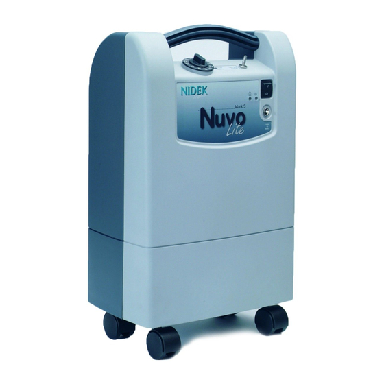
Mark 5 Nuvo® Lite Oxygen Concentrator
Service Manual
Nidek Medical Products, Inc. 3949 Valley East Industrial Drive
Birmingham, Alabama 35217 USA
Telephone: (205) 856-7200 • 24-Hour Fax: (205) 856-0533
Nidek Medical is a trademark of Nidek Medical Products, Inc.
Mark 5 Nuvo® Lite is a registered trademark of Nidek Medical Products, Inc
2010-8405 Rev E
Jan 2011
1 of 48
Advertisement
Chapters
Table of Contents
Troubleshooting

Related Manuals for Nidek Medical Mark 5 Nuvo Lite


Summary of Contents for Nidek Medical Mark 5 Nuvo Lite
- Page 1 Birmingham, Alabama 35217 USA Telephone: (205) 856-7200 • 24-Hour Fax: (205) 856-0533 Nidek Medical is a trademark of Nidek Medical Products, Inc. Mark 5 Nuvo® Lite is a registered trademark of Nidek Medical Products, Inc 2010-8405 Rev E Jan 2011...
- Page 2 Table of Contents General Safety Instructions Production and Use of Oxygen Use and Maintenance of the Device Standards and Regulations Section 1.0 Introduction Home Service Provider Responsibility Important Notice and Symbol Explanations Functional Specifications Section 2.0 Operational Check and Concentration Test Description of Operation Operation Check Alarm System...
-
Page 3: Table Of Contents
Compressor 5.3.1 Compressor Replacement 5.3.2 Capacitor Replacement Process Control Valve Sieve Bed Replacement 5.5.1 Sieve Bed Removal 5.5.2 Sieve Bed Installation Cabinet Fan Replacement Circuit Board Replacement 5.7.1 Circuit Board Removal 5.7.2 Circuit Board Installation Product Regulator Check and Setting 5.8.1 Product Regulator Cleaning or Rebuilding Pressure Switch Replacement Circuit Breaker Replacement... - Page 4 Appendices Exploded A-1: OCSI Pneumatic Diagram Drawings A-2: Standard Pneumatic Diagram A-2-A: No-Flow Alarm Pneumatic Diagram A-3: 115 Volt Electrical Schematic A-4: 230 Volt Electrical Schematic A-5: Electrical Schematic for No Flow Board A-6: Electrical & Compressor Assembly A-6-A: Electrical & Compressor Assembly Parts A-6-B: Compressor Mounting Bracket Parts A-7:...
- Page 5 Do not use an extension cord or multiple sockets which can create sparks and therefore pose a fire risk. Use of the MARK 5 NUVO Lite must be restricted solely to oxygen therapy on medical prescription in compliance with the daily rate and duration. Use in other circumstances may represent a hazard to patient health.
- Page 6 Service providers have a responsibility to evaluate any complaints received from their direct customers. ( Ref. CFR 820.198 ). Nidek Medical does not have direct links to your customers. Your evaluation should include the following: ● Determine if the complaint warrants action by Nidek Medical, ●...
- Page 7 Be available to service each patient at any time. Maintain the MARK 5 NUVO Lite in accordance with Section 4.0. Repair components and replace parts only as outlined in this manual. Use only Nidek Medical parts for replacement in MARK 5 NUVO Lite Oxygen Concentrators.
- Page 8 Operational Check Nidek Medical runs each device through a burn in period and tests every MARK 5 NUVO Lite Oxygen Concentrator thoroughly after manufacture before releasing for shipment. As the home service provider, it is your responsibility to perform the following test to ensure that no damage occurred in shipping or handling.
- Page 9 Test the unit upon delivery to a patient and at periodic intervals. Home Service Providers, based on their expertise and documentation, may establish and implement their own plans for checking oxygen concentration. Consult Nidek Medical’s Service and Maintenance Log (A-11) for the recommended intervals for testing.
- Page 10 Patient Instructions General Instructions It is important that patients thoroughly understand how to operate the Nidek Medical MARK 5 NUVO Lite unit. This enables proper treatment as prescribed by a qualified, licensed physician. You must explain that the purpose of this therapy is to alleviate symptoms. If patients experience any discomfort or the unit alarms, they must notify their Home Service Provider and/or physician immediately.
- Page 11 90 days, which is the default time period recommended for providers who do not choose to establish their own method. Nidek Medical does not require preventive maintenance on the concentrator. You do not need to perform any maintenance as long as the MARK 5 NUVO Lite unit remains within specifications at the prescribed flow rate.
- Page 12 NOTE: The filter may require more frequent cleaning if the MARK 5 NUVO Lite unit operates in a harsh environment such as a house heated by wood, kerosene, or oil, or one with excessive cooking, cigarette smoke or atmospheric dust. 4.1.2 Final Product Filter Replacement The final product filter does not require periodic replacement;...
- Page 13 Service Components The design of the Nidek Medical MARK 5 NUVO Lite Oxygen Concentrator allows for easy access and removal of most components. This allows you to perform scheduled maintenance, repair, and replacement of parts with minimal time and effort. The inlet air filter is conveniently located behind the cabinet air filter on the cabinet back.
-
Page 14: Compressor
You can continue a patient’s therapy on the MARK 5 NUVO Lite unit as long as the oxygen concentration level at the prescribed liter flow rate is within Nidek Medical’s specification limits. Refer to Section 2.4. -
Page 15: Compressor Replacement
● Sound Level The sound level is largely determined by the condition of the compressor’s bearings. There are four bearings located within the compressor that allow the inner components of the compressor to rotate. If the bearings wear to the point that they become loose and noisy, the compressor becomes noticeably loud and needs servicing. -
Page 16: Process Control Valve
Process Control Valve The MARK 5 NUVO Lite uses a solenoid powered poppet valve assembly to control the air separation process. There is a feed port that connects to the compressor and an exhaust port that discharges through an integral exhaust muffler. There are three possible valve states as follows: Air feed connected to sieve bed A and exhaust connected to sieve bed B. -
Page 17: Cabinet Fan Replacement
NOTE: Even small leaks can affect concentrator performance and can cause contamination of sieve. Careful leak testing is important. Cabinet Fan Replacement The cabinet fan for the MARK 5 NUVO Lite is located adjacent to the compressor. Refer to the troubleshooting chart in Section 6.0 of this manual for instances where replacement of the fan may be required. -
Page 18: Circuit Board Installation
5. Non OCSI units: Cut tie-wrap and remove pressure sensor line. 6. Remove the screws that attach the board to the front cabinet. 7. Remove the circuit board. NOTE: Handle the new circuit board only by the edges to prevent electrostatic damage to the unit. -
Page 19: Product Regulator Cleaning Or Rebuilding
5.8.1 Product Regulator Cleaning or Rebuilding Clean or rebuild the product regulator if the regulator cannot be adjusted. Set the I/0 (ON/OFF) switch to the 0 (OFF) position, and unplug the power cord, 2. Remove the back cabinet. 3. Remove the regulator from the tee on top of the solenoid valve assembly. 4. -
Page 20: I/0 (On/Off) Power Switch Replacement
5.11 I/0 (ON/OFF) Power Switch Replacement 5.11.1 I/0 (ON/OFF) Power Switch Removal 1. Set the I/0 (ON/OFF) switch to the 0 (OFF) position and unplug the power cord. 2. Remove both the back cabinet. 3. Disconnect the I/0 (ON/OFF) switch leads from the back of the switch being careful to note the position of each. -
Page 21: Power Cord Replacement
5.15 Power Cord Replacement 1. Set the I/0 (ON/OFF) switch to the 0 (OFF) position and unplug the power cord. 2. Remove the cabinet back. Clip the power cord retaining tie wrap 3. Slide the power cord strain relief reinforcement upwards to remove it from the mounting location at the bottom of the front cabinet. - Page 22 Figure 6.1.1 normal operating configuration (OCSI unit). Figure 6.1.2 normal operating configuration (standard unit). 22 of 48 Jan 2011 2010-8405 Rev E...
-
Page 23: High Air Pressure (P1)
Figure 6.1.3 configuration with test ports 6.1.1 High Operating Air Pressure (P1) Higher than normal operating pressure may indicate any of the following: ► A restrictive exhaust muffler, which does not allow the waste (purge) gas to exit the system freely. -
Page 24: Product Pressure Test (P2)
Ensure that the concentration level at the desired liter flow is within specifications listed in section 2.4. If it is below specifications, replace or repair the compressor. 6.2 Product Pressure Test (P2) Testing the product pressure is a useful diagnostic tool when a concentrator has low purity and requires servicing. -
Page 25: General Troubleshooting
General Troubleshooting Before reviewing the troubleshooting chart, the following steps may be useful to isolate any malfunctions: 1. Turn the concentrator on. If unit does not turn on, refer to troubleshooting chart. 2. Make sure all filters are clean. 3. Connect test pressure gauge to the outlet fitting of the unit. The pressure should read 7.1 psig (49 kPa) ±... -
Page 26: Troubleshooting Chart
Low Oxygen Concentration Verify O xygen Flow R ate M easure Air Pressure Low Pressure H igh Pressure R eplace Air Inlet Filter Replace M uffler C heck for Foam s Leaks Check C heck the C ontrol C om pressor Valve N orm al Air Pressure... - Page 27 Problem Probable Cause Solution Compressor runs with Defective sieve beds. Replace sieve beds. intermittent high pressure alarm and low oxygen Restriction in exhaust muffler. Replace or clean muffler. concentration. Defective valve. Replace sieve module. Compressor relief valve Defective control valve. Replace sieve module.
- Page 28 Problem Probable Cause Solution Cabinet fan does not turn. Defective cabinet fan. Replace cabinet fan. Defective electrical Check electrical connections. connections. Limited or Iow flow. Restriction in humidifier or Replace humidifier or tubing. tubing. Product regulator set too low. Adjust regulator setting. Leak.
-
Page 29: Tool Kit And Pressure Test Gauge
3/8-inch combination wrench. ► For checking the Oxygen purity at the Concentrator. Nidek Medical recommends Part # 6500-4220 ► An accurate pressure test gauge to take both P-1 and P-2 pressure readings on the MARK 5 NUVO Lite unit should be kept available at all times. This gauge kit allows connections to the pressure test locations. -
Page 30: Ocsi Pneumatic Diagram
Flow Schematic OCSI Option 30 of 48 Jan 2011 2010-8405 Rev E... -
Page 31: Standard Pneumatic Diagram
Flow Schematic Standard Non-OCSI Option 2010-8405 Rev E Jan 2011 31 of 48... -
Page 32: A-2-A
A-2-A Flow Schematic No-Flow Option 32 of 48 Jan 2011 2010-8405 Rev E... -
Page 33: 115 Volt Electrical Schematic
115 Volt Electrical Schematic R = Red W = White K = Black BL = Blue BR = Brown GR = Green YL = Yellow PU = Purple 115 Volt Electrical Schematic 2010-8405 Rev E Jan 2011 33 of 48... -
Page 34: 230 Volt Electrical Schematic
230 Volt Electrical Schematic R = Red W = White K = Black BL = Blue BR = Brown GR = Green YL = Yellow PU = Purple 230 Volt Electrical Schematic 34 of 48 Jan 2011 2010-8405 Rev E... -
Page 35: Electrical Schematic For No Flow Board
230 Volt No Flow Option Electrical Schematic. R = Red W = White K = Black BL = Blue BR = Brown GR = Green YL = Yellow PU = Purple NOTE: 230 Volt Version is Shown For 115 Volt Version: 1. -
Page 36: Electrical & Compressor Assembly
ELECTRICAL & COMPRESSOR ASSEMBLY 36 of 48 Jan 2011 2010-8405 Rev E... - Page 37 400-1513 SHUNT, VOLTAGE SELECTION 8400-5018 HOURMETER AC 100-230 V 50/60 9250-1170 HOURMETER,UNV W/O CLIP 8400-1012 SCREW, 8-32 x 5/8"LG.HEX HEAD 8400-1010 BRACKET,COMPRESSOR 8400-1049 BRACKET, HEAT EXCHANGER 8400-1052 FITTING,COMPRESSOR 8400-1053 FITTING,COMPRESSOR 8400-1016 SPRING, EXTENSION 8400-1094 EXCHANGER,HEAT 8400-1095 EXCHANGER,HEAT 8400-1161 TUBING,5/16ODx3/16IDx12.5"LG. 8400-1162 TUBING, 5/16ODx3/16IDx9.75"LG.
- Page 38 Part Reference Call-Out Unit of Number Number Part Description Required Measure 8400-1010 BRACKET,COMPRESSOR 8400-1013 RETAINER, SPRING 8400-1016 SPRING, EXTENSION 8400-1030 GROMMET,.75"IDX1.0"HOLE 8400-1009 CAP, VINYL 3-16" 8400-1017 GROMMET, SPRING EYE COMPRESSOR MOUNTING BRACKET PARTS A -6-B 38 of 48 Jan 2011 2010-8405 Rev E...
-
Page 39: Front Cabinet Standard Assembly
CABINET, FRONT ASSEMBLY (STD) 2010-8405 Rev E Jan 2011 39 of 48... - Page 40 Part Reference Call-Out Unit of Number Number Part Description Required Measure 8400-0002 CABINET,FRONT 9251-1330 VALVE, FCV 1/8-5.0 LPM 8400-1331 KNOB,FLOW 0.125 TO 5.0 FLOW 9251-1332 RING,LOCK-OUT 9251-1335 CLIP,D STYLE 8400-1020 FITTING, OXYGEN OUTLET 8400-1024 WASHER, 3/8 STAR O2 OUTLET LITE 8400-1022 NUT 3/8-24 O2 OUTLET LITE 7631-1053...
-
Page 41: Front Cabinet Ocsi Assembly
CABINET, FRONT ASSEMBLY OCSI 2010-8405 Rev E Jan 2011 41 of 48... - Page 42 Part Reference Call-Out Unit of Number Number Part Description Required Measure 8400-0002 CABINET,FRONT 9251-1330 VALVE, FCV 1/8-5.0 LPM 8400-1331 KNOB,FLOW 0.125 TO 5.0 FLOW 9251-1332 RING,LOCK-OUT 9251-1335 CLIP,D STYLE 8400-1020 FITTING, OXYGEN OUTLET 8400-1024 WASHER,3/8 STAR O2 OUTLET LITE 8400-1022 NUT 3/8-24 O2 OUTLET LITE 7631-1053 FILTER, FINAL PRODUCT...
-
Page 43: Back Cabinet Assembly
CABINET, BACK ASSEMBLY 2010-8405 Rev E Jan 2011 43 of 48... - Page 44 Part Reference Call-Out Unit of Number Number Part Description Required Measure 8400-0001 CABINET,BACK 8400-0022 RETAINER,CORD 8400-1025 FILTER,CABINET INLET 8400-1028 HOSE, COMPRESSOR INLET. 8400-1059 ADAPTER, FILTER 8400-0029 RETAINER,CORD BUCKLE 8400-0023 RETAINER,CORD RIVET 8400-1180 FILTER AIR INLET. 6814-9228 ELBOW, 1/2 DOUBLE BARB, NYLON 5190-2233 HOLDER TIE WRAP 9030-6008...
-
Page 45: Module Assembly
A-10 MODULE NEW ASSEMBLY 5LPM 2010-8405 Rev E Jan 2011 45 of 48... - Page 46 Part Reference Call-Out Unit of Number Number Part Description Required Measure 8400-1060 REGULATOR, 2-PORT 8400-1165 FITTING VALVE 5/16"X3/8 8400-1200 VALVE ASSY 8400-1236 TEE,ADAPTER NYLON 8400-1253 O-RING, REGULATOR TEE -204 8644-9401 PLUG, 1/4~ ODT PUSH IN A-10-A MODULE ASSEMBLY REPLACEMENT PARTS 46 of 48 Jan 2011 2010-8405 Rev E...
- Page 47 Nidek Medical Oxygen Concentrator Service and Maintenance Log Model Number ________________ Serial Number ___________________ Initial Inspection Between-Patient Maintenance 1. Upon receipt, check the unit for shipping 1. Remove oxygen tubing, cannula, and humidifier damage. Notify shipping company if damaged. bottle and discard.
- Page 48 Please maintain a log of all maintenance activities performed on Serial Number______________Model_____________ this unit. Alarms Additional Information (Work Done, Filter Changes, Date Hours % O2 Check Comments, etc) Inspection Prior to Putting Into Service In-Service Checks Medical device regulations require users and service personnel to notify manufacturers of any incidents that, if repeated, could cause injury to any person.
Need help?
Do you have a question about the Mark 5 Nuvo Lite and is the answer not in the manual?
Questions and answers