
Related Manuals for OPGAL EyeCGas 2.0

Summary of Contents for OPGAL EyeCGas 2.0
- Page 1 OGI – Optical Gas Imager, Camera User Manual Copyright © 2018 Opgal, all rights reserved. Rev 01 | Doc P/N: UM-8G9A0000B...
- Page 2 www. Home Safety Powering Off Camera Battery Warnings and Cautions Replacing the Battery General Warnings Replacing the Lens Camera Certification Replacing the Optical Filter Technical Specifications EyeCGas® 2.0 Nameplate Overview Maintenance System Layout Cleaning the Lens Camera Overview Cleaning the LCD Screen and Camera Body Troubleshooting Opening the Box Operation...
-
Page 3: Battery Warnings And Cautions
▪ Do not disassemble the battery. ▪ Do not expose the battery pack(s) to fire or extremely high temperatures. ▪ Use only EyeCGas® 2.0 battery packs manufactured by Opgal (part ▪ Do not cause damage to or attempt to short circuit the battery pack(s). -
Page 4: General Warnings
www. Safety | General Warnings General Warnings WARNING - EXPLOSION HAZARD Do not connect or disconnect devices to EyeCGas® 2.0 while circuit is live, unless area is known to be non-hazardous. Camera Certification ATEX HAZARDOUS AREA SAFETY CERTIFICATION FOR ZONE2 ATEX II 3G Ex nL IIC T6 EN 60079-0:2012/A11:2013 EN 60079-11:2012... -
Page 5: Eyecgas® 2.0 Nameplate
www. Safety | EyeCGas® 2.0 Nameplate EyeCGas® 2.0 Nameplate The EyeCGas® 2.0 nameplate is located on the camera behind the battery. The nameplate contains the product serial number (A) that may be needed when requesting service. MENU SAFETY OVERVIEW OPERATION TECHNICAL MAINTENANCE... - Page 6 www. Overview | EyeCGas® 2.0 Nameplate Overview EyeCGas® 2.0 is a handheld infrared camera engineered specifically for use in gas leak detection. The EyeCGas® 2.0 camera is designed to withstand the rigors of everyday handling in refineries and chemical plants, and also incorporates safeguards for use in hot air environments. EyeCGas® 2.0 uses include: maintenance, video documentation of plant survey inspection, and on-line update of database.
-
Page 7: System Layout
www. Overview | System Layout System Layout Wi-Fi connectivity (camera as hotspot) MENU SAFETY OVERVIEW OPERATION TECHNICAL MAINTENANCE TROUBLESHOOTING TECHNICAL SPECIFICATIONS SUPPORT EyeCGas® 2.0 | User Manual Rev 01 | Doc P/N: UM-8G9A0000B... -
Page 8: Camera Overview
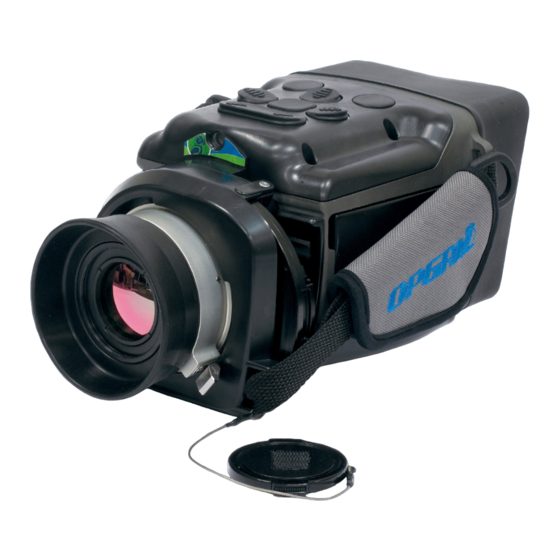
www. Overview | Camera Overview Camera Overview EyeCGas® 2.0 is a handheld infrared camera capable of autonomous imaging and recording operations for the detection of gas leaks. It is designed to withstand the rigors of everyday handling in refineries and chemical plants. The EyeCGas®... - Page 9 www. Overview | Camera Overview KEYPAD BUTTONS OVERVIEW A set of buttons is used to both control operation of the EyeCGas® 2.0 camera and to navigate through the camera's on-screen menu. Keypad functionality depends on the state of EyeCGas® 2.0: Camera is powered off (see Powering On...
-
Page 10: Lcd Display
www. Overview | Camera Overview LCD DISPLAY The LCD screen (A) displays color video when filming in visible mode, and high-resolution grayscale video when filming in the normal, enhanced, and thermography viewing modes. NOTE To magnify the LCD screen image by 300%, and for easier viewing in brightly lit areas, attach the glare shield (see Attaching the Glare Shield). - Page 11 www. Overview | Camera Overview AIRFLOW FAN An external fan is used to indirectly cool the electronic components inside EyeCGas® 2.0. The airflow fan takes in air from the bottom of the camera (A) and expels it from the side (B). CAUTION Verify proper operation of the fan.
-
Page 12: Tripod Mount
www. Overview | Camera Overview TRIPOD MOUNT The tripod mount (A) allows the camera to connect to a tripod. CAUTION Ensure the camera is securely fastened to the tripod and the tripod legs are stable. MENU SAFETY OVERVIEW OPERATION TECHNICAL MAINTENANCE TROUBLESHOOTING... -
Page 13: Opening The Box
www. Overview | Opening the Box Opening the Box After receiving the EyeCGas® 2.0 delivery, open the box and verify that the package contains all the parts mentioned in List of Standard Components any optional accessories ordered separately (see List of Optional Components). - Page 14 www. Overview | Opening the Box ITEM IMAGE NAME PART NUMBER MORE INFORMATION Prevents screen glare which impedes direct viewing of the LCD display. Also Glare Shield 8G9A0020C magnifies the LCD screen 300%. Attaching the Glare Shield. One battery pack powers the EyeCGas® 2.0 camera continuously for over five hours.
- Page 15 www. Overview | Opening the Box ITEM IMAGE NAME PART NUMBER MORE INFORMATION Connects EyeCGas® 2.0 camera to a computer or tablet. USB 2.0 Cable 1002056ALF Connecting via USB. Enables cleaning of the camera lens. Lens Cleaning Kit 1000932A Cleaning the Lens.
-
Page 16: List Of Optional Components
www. Overview | Opening the Box LIST OF OPTIONAL COMPONENTS NAME PART NUMBER MORE INFORMATION Enables an audio track to be recorded during video recording. Headset for EyeCGas® 2.0 8G9A0050B Attaching the Headset. AC Power Supply 8G9K0500A Enables powering of the camera through a wall or car power outlet. Triple Battery Charger 8G9M6000B Enables charging of up to three battery packs. - Page 17 www. Overview | Opening the Box NAME PART NUMBER MORE INFORMATION Allows for replacement of the EyeCGas® 2.0 optical filter. Optical Filter Replacement 8G9K0120A Replacing the Optical Filter. MENU SAFETY OVERVIEW OPERATION TECHNICAL MAINTENANCE TROUBLESHOOTING TECHNICAL SPECIFICATIONS SUPPORT EyeCGas® 2.0 | User Manual Rev 01 | Doc P/N: UM-8G9A0000B...
-
Page 18: Operation
www. Operation | Opening the Box Operation This chapter provides information on how to operate the EyeCGas® 2.0 camera and includes: Preparation for Use Camera Startup Viewing Modes Frequently Used Operations Camera Settings Attaching Accessories to Camera Powering Off Camera Replacing the Battery Replacing the Lens Replacing the Optical Filter... -
Page 19: Preparation For Use
www. Operation | Preparation for Use Preparation for Use This section provides information on preparing the camera for use and includes: Charging the Battery Attaching the Battery Adjusting the Side Straps MENU SAFETY OVERVIEW OPERATION TECHNICAL MAINTENANCE TROUBLESHOOTING TECHNICAL SPECIFICATIONS SUPPORT EyeCGas®... -
Page 20: Charging The Battery
www. Operation | Preparation for Use CHARGING THE BATTERY To charge a battery: 1. Plug the battery charger into a power outlet. 2. Remove the adhesive tape from battery contacts. 3. Insert the battery into the charger until it latches. LEDs on the battery charger indicates the following: Red - charging Green - fully charged... -
Page 21: Attaching The Battery
www. Operation | Preparation for Use ATTACHING THE BATTERY To attach a battery to the camera: 1. Ensure the battery contacts (A) are facing up. 2. Slide the battery up along the camera until it snaps in place (B). NOTES ▪... - Page 22 www. Operation | Preparation for Use ADJUSTING THE SIDE STRAPS The straps on both sides of the camera allows the camera to be held comfortably and securely, and also allow for comfortable operation of the keypad buttons. To adjust the side straps: 1.
-
Page 23: Camera Startup
www. Operation | Camera Startup Camera Startup This section provides information on the camera startup sequence and includes: Powering On Camera Power-Up Sequence Removing Lens Cover Screen Overlay MENU SAFETY OVERVIEW OPERATION TECHNICAL MAINTENANCE TROUBLESHOOTING TECHNICAL SPECIFICATIONS SUPPORT EyeCGas® 2.0 | User Manual Rev 01 | Doc P/N: UM-8G9A0000B... - Page 24 www. Operation | Camera Startup POWERING ON CAMERA Before powering on the camera, ensure the battery is properly inserted and fully charged (see Attaching the Battery). To power on the camera: 1. Ensure the lens cover is mounted on the lens (A). 2.
-
Page 25: Power-Up Sequence
Operation | Camera Startup POWER-UP SEQUENCE The camera goes through the following power-up sequence: 1. A black screen, followed by the Opgal logo, are displayed for approximately ten seconds. 2. The cooler starts. 3. The camera starts in visible mode. - Page 26 www. Operation | Camera Startup REMOVING LENS COVER Remove the lens cover once the power-up sequence has completed. To remove the lens cover: 1. Verify the lens cover is tied to the side of the camera (A). 2. Push in both latches on either side of the cover (B). 3.
- Page 27 www. Operation | Camera Startup SCREEN OVERLAY After the camera has powered up, the following indicators are displayed on the screen: Viewing Status Indicators (A) – includes indicators for viewing mode, zoom value, and image polarity. Date and time (B) – date is displayed in MM/DD/YY or DD/MM/YY format;...
- Page 28 www. Operation | Camera Startup Viewing Status Indicators The viewing status indicators include the following: Viewing Mode (A) – options include: VIS – visible » NOR – normal » ENH – enhanced » TMF – thermography » Viewing Modes. Zoom value (B) –...
- Page 29 www. Operation | Camera Startup Camera Status Indicators The camera status indicators include the following icons: Cooler (A) – indicates cooler is active. Icon blinks during cool down state, and appears with a red cross (E) when cooler is deactivated (see Activating/Deactivating Cooler).
- Page 30 www. Operation | Camera Startup Connection Status Indicators The connection status indicators include the following icons: USB (A) – indicates EyeCGas® 2.0 is connected to a computer or tablet via a USB cable with the Net Adapter option enabled (see Connecting via USB).
-
Page 31: Viewing Modes
www. Operation | Viewing Modes Viewing Modes Keypad EyeCGas® 2.0 operates in the following viewing modes: Visible Mode Normal Mode Enhanced Mode Thermography Mode SWITCHING BETWEEN VIEWING MODES To switch between viewing modes, press the mode button (A). The viewing mode indicator on the LCD display (B) indicates the currently selected mode. - Page 32 www. Operation | Viewing Modes VISIBLE MODE In visible mode, EyeCGas® 2.0 displays video using the HD video camera. Visible mode is used for situational awareness and component identification. The following indicators are specific to this mode: VIS (A) – indicates visible mode is active. NOTE Operations available in visible mode are: ▪...
-
Page 33: Normal Mode
www. Operation | Viewing Modes NORMAL MODE In normal mode, EyeCGas® 2.0 produces a very smooth thermal image. Normal mode is used to detect medium to large sized gas leaks in environments with high temperature differences between the gas and the background. -
Page 34: Enhanced Mode
www. Operation | Viewing Modes ENHANCED MODE In enhanced mode, EyeCGas® 2.0 utilizes proprietary algorithms to enhance gas detection. Enhanced mode is used for detecting low gas flow leakages and when working in an environment with a uniform (low-contrast) background. - Page 35 www. Operation | Viewing Modes THERMOGRAPHY MODE In thermography mode, EyeCGas® 2.0 identifies surface temperature variations of objects and displays these variations as differences in color. Colors are determined based on the color palette selected (see Selecting Color Palette). The following indicators are specific to this mode: TMG (A) –...
-
Page 36: Frequently Used Operations
www. Operation | Frequently Used Operations Frequently Used Operations This section reviews frequently used camera operations and includes: Keypad Buttons Used During Camera Operation Recording Video Taking a Snapshot Zooming Performing Non-Uniformity Correction (NUC) Selecting Polarity Selecting Color Palette Choosing Enhancement Level Choosing Emissivity Value NOTE... - Page 37 www. Operation | Frequently Used Operations KEYPAD BUTTONS USED DURING CAMERA OPERATION The following buttons are used in all viewing modes: Power Off Viewing Mode Record Snapshot Polarity Power Off Color Palette Zoom The following button is used in normal and enhanced viewing mode: Polarity Viewing Mode...
-
Page 38: Recording Video
www. Operation | Frequently Used Operations RECORDING VIDEO Keypad To record video: 1. Set the camera to the required viewing mode (see Switching Between Viewing Modes). 2. Press the record button (A). A red indicator (B) starts blinking. 3. To stop the recording, press the record button (A). The red icon disappears and the video is saved in the camera's internal memory. -
Page 39: Taking A Snapshot
www. Operation | Frequently Used Operations TAKING A SNAPSHOT Keypad To take a snapshot of the image shown on the screen, press the snapshot button (A). A blue icon (B) briefly appears on the screen, and the image is saved in the camera's internal memory. - Page 40 www. Operation | Frequently Used Operations ZOOMING Keypad To activate digital zoom, press the zoom button (A). Each button press advances the digital zoom as follows: visible mode only (cycles back to 1x) The current zoom level is indicated on the display (B). NOTES ▪...
- Page 41 www. Operation | Frequently Used Operations PERFORMING NON-UNIFORMITY CORRECTION (NUC) The NUC process corrects for image noise or artifacts caused by external or internal temperature changes. To perform the NUC process: 1. Mount the lens cover (A) on the camera lens. 2.
- Page 42 www. Operation | Frequently Used Operations SELECTING POLARITY Keypad Polarity determines whether hot objects are displayed as white or black. To select polarity: 1. Select normal or enhanced viewing mode (see Switching Between Viewing Modes). 2. Press the polarity button (A) to switch between the following two modes: White Hot (WH) mode –...
- Page 43 www. Operation | Frequently Used Operations SELECTING COLOR PALETTE A color palette is a predefined range of colors which correspond to variations Keypad in surface temperature of objects. A palette should be chosen which best shows thermal differences in the scene. To select a color palette: 1.
- Page 44 www. Operation | Frequently Used Operations CHOOSING ENHANCEMENT LEVEL Keypad A low enhancement level allows the infrared sensor to be more sensitive to gas. However, low enhancement levels also generate grainier images. An optimum level should thus be chosen between gas detection and clear image generation. To choose enhancement level: 1.
- Page 45 www. Operation | Frequently Used Operations CHOOSING EMISSIVITY VALUE Emissivity Values of Keypad Emissivity value is chosen according to the physical characteristic of the Common Materials material being reviewed. To choose emissivity value: 1. Select thermography viewing mode (see Switching Between Viewing Modes).
-
Page 46: Camera Settings
www. Operation | Camera Settings Camera Settings This section reviews the various camera settings configured using the on- screen menu system and includes: Keypad Buttons Used During Menu Configuration Menu Navigation Menu Overview File Management Settings Connectivity Imaging Modes MENU SAFETY OVERVIEW... - Page 47 www. Operation | Camera Settings KEYPAD BUTTONS USED DURING MENU CONFIGURATION The following buttons are used to access and navigate the menu system: Menu Left navigation Up navigation Right navigation Menu Down navigation Up navigation Left navigation Right navigation Down navigation MENU SAFETY...
-
Page 48: Menu Navigation
www. Operation | Camera Settings MENU NAVIGATION EyeCGas® 2.0's menu system consists of four menu tabs. Under each tab is a list of options which contain either sub-menus or information. The general process for navigating the menu system is as follows: Displaying the Menu Press the menu button (C). - Page 49 www. Operation | Camera Settings Scrolling Vertically Between Menu Options Press the down (A) or up (B) navigation button to scroll between menu options. Selecting a Menu Option Press the right (A) navigation button to select a menu option. MENU SAFETY OVERVIEW...
-
Page 50: Menu Overview
www. Operation | Camera Settings MENU OVERVIEW Use the right and left navigation buttons to navigate between menu tabs. Connectivity Imaging Modes File Manager Settings Play XX.ts Brightness Wi-Fi Active Modes YY.jpeg Delete Key Mapping Bluetooth IR Zoom Delete All Set Time Bluetooth IR Polarity... -
Page 51: File Management
www. Operation | Camera Settings FILE MANAGEMENT The file manager tab allows for viewing and deleting videos and images saved in the camera's internal memory. This section includes: Playing Videos Viewing Images Deleting a Single Video or Image Deleting All Videos and Images Transferring Files using Mass Storage Transferring Files using FTP MENU... - Page 52 www. Operation | Camera Settings Playing Videos Display the menu. The file manager tab is already selected. XX.ts Play Click the right navigation button Scroll to and select the relevant video file. YY.jpeg to make selection. Delete Select Play. Delete All NOTE Video files are saved in .ts format, a video streaming file format used for...
- Page 53 www. Operation | Camera Settings Deleting a Single Video or Image Display the menu. The file manager tab is already selected. XX.ts Play Scroll to and select the relevant video or image file. YY.jpeg Delete Click the right Scroll to and select Delete.
- Page 54 www. Operation | Camera Settings Transferring Files using Mass Storage To transfer files from the camera to a computer using the USB mass storage option: 1. Select the mass storage option under USB settings (see Connecting via USB). 2. Connect the USB cable between the camera and a computer. 3.
- Page 55 www. Operation | Camera Settings SETTINGS The settings tab enables setting camera preferences and viewing system information. This section includes: Adjusting LCD Brightness Displaying Keypad Map Setting Date and Time Activating/Deactivating Cooler Selecting Language Viewing System Information Viewing About Information MENU SAFETY OVERVIEW...
- Page 56 www. Operation | Camera Settings Adjusting LCD Brightness LCD display brightness levels are set from 10% to 100% by increments of 10. Brightness Brightness Click the right To adjust the LCD brightness: navigation button to make selection. Display the menu.
- Page 57 www. Operation | Camera Settings Displaying Keypad Map The keypad map (A) assists in recognizing keypad button functionality, which changes depending on the current operating state of EyeCGas® 2.0 (see Brightness Keypad Buttons Overview). The keypad map is an on-screen diagram that includes a descriptor of the each button's functionality.
- Page 58 www. Operation | Camera Settings Setting Date and Time This section explains how to set the EyeCGas® 2.0 internal date and time. Brightness The date and time appear at the top of the LCD display (see Screen Overlay). To set the date and time: Key Mapping Display the menu.
- Page 59 www. Operation | Camera Settings Activating/Deactivating Cooler EyeCGas® 2.0 uses a cooled IR sensor, and thus the sensor cooler must be Brightness activated when using the IR camera. When the cooler is off, the camera switches automatically to visible mode.
- Page 60 www. Operation | Camera Settings Viewing System Information System information includes software version number, network status, and Key Mapping amount of internal memory left. To view system information: Set Time Display the menu. Cooler Navigate to the settings tab. Scroll to and select...
- Page 61 www. Operation | Camera Settings CONNECTIVITY The connectivity tab enables connecting EyeCGas® 2.0 to peripheral devices using Wi-Fi, Bluetooth, GPS, and USB. This section includes: Connecting via Wi-Fi Connecting via Bluetooth Connecting to GPS Connecting via USB Enabling Video Streaming MENU SAFETY OVERVIEW...
- Page 62 www. Operation | Camera Settings Connecting via Wi-Fi This section reviews the tasks associated with connecting a peripheral device to EyeCGas® 2.0 using Wi-Fi communication. Wi-Fi Hot Spot Click the right navigation button To enable Wi-Fi connection: to make selection. Bluetooth Display the menu.
- Page 63 www. Operation | Camera Settings Connecting via Bluetooth Bluetooth connectivity allows the camera to connect to devices such as tablets, analyzers, and external GPS. Wi-Fi To connect to a Bluetooth device: Bluetooth Click the right Display the menu. navigation button to make selection.
- Page 64 www. Operation | Camera Settings Connecting to GPS GPS connectivity allows for geo-locating the position where the inspection is being performed. Wi-Fi To connect to GPS: Bluetooth Display the menu. Bluetooth Navigate to the connectivity tab. Setup Scroll to and select GPS.
- Page 65 www. Operation | Camera Settings Connecting via USB USB connectivity allows for networking communication and file transfer. Bluetooth To connect to a computer or tablet via USB: Display the menu. Bluetooth Setup Navigate to the connectivity tab. Scroll to and select USB.
- Page 66 www. Operation | Camera Settings Enabling Video Streaming EyeCGas® 2.0 can stream live video to peripheral devices connected via Wi- Fi or USB. To receive the video stream, the peripheral device must run a Bluetooth suitable media application (e.g., VLC Media Player or Neptune Player). Setup To enable video streaming: 1.
- Page 67 www. Operation | Camera Settings In a media application: 6. Select Stream (B) from the Media menu (A). MENU SAFETY OVERVIEW OPERATION TECHNICAL MAINTENANCE TROUBLESHOOTING TECHNICAL SPECIFICATIONS SUPPORT EyeCGas® 2.0 | User Manual Rev 01 | Doc P/N: UM-8G9A0000B...
- Page 68 www. Operation | Camera Settings 7. Click the Network tab (A). 8. Type the URL (B). The URL is constructed as follows: rtps://[IP address (D) found in system info screen]/video.sdp rtsp://192.168.1.5/video.sdp 9. Click Stream (C). NOTES ▪ The live video stream displays the same viewing mode as that shown on the camera's LCD display.
-
Page 69: Imaging Modes
www. Operation | Camera Settings IMAGING MODES This section include: Defining Active Modes Setting Zoom Level Setting Polarity Setting Enhancement Level Defining Thermography Mode Settings MENU SAFETY OVERVIEW OPERATION TECHNICAL MAINTENANCE TROUBLESHOOTING TECHNICAL SPECIFICATIONS SUPPORT EyeCGas® 2.0 | User Manual Rev 01 | Doc P/N: UM-8G9A0000B... - Page 70 www. Operation | Camera Settings Defining Active Modes Keypad Pressing the mode button (A) on the keypad switches between viewing modes (see Switching Between Viewing Modes). To select whether enhanced thermography modes are available when the mode button is pressed: Display the menu.
- Page 71 www. Operation | Camera Settings Setting Zoom Level This section reviews the option to set a zoom level using the menu system. Active Modes To set zoom level: Display the menu. IR Zoom Click the right navigation button Navigate to the imaging modes tab.
- Page 72 www. Operation | Camera Settings Setting Polarity This section reviews the option to define a polarity value when using normal Active Modes enhanced viewing modes. To set polarity value: IR Zoom Display the menu. IR Polarity Click the right Navigate to the imaging modes tab.
- Page 73 www. Operation | Camera Settings Setting Enhancement Level This section reviews the option to define an enhancement level when using enhanced viewing mode. Active Modes To set enhancement level: IR Zoom Display the menu. IR Polarity Navigate to the imaging modes tab. Scroll to and select...
- Page 74 www. Operation | Camera Settings Defining Thermography Mode Settings This section reviews the option to define the following thermography Enhanced mode settings when using thermography viewing mode: temperature unit, emissivity value, reflected temperature, and color palette. Thermography Click the right Units Celsius To define thermography mode settings:...
- Page 75 www. Operation | Camera Settings Defining Thermography Mode Settings (cont.) Enhanced Select Tref (C) and choose the desired Tref level using the up » Thermography Units and down navigation buttons. Emissivity Tref 95 K Click the right Select Palette (D) and select from the following color palette »...
-
Page 76: Attaching Accessories To Camera
www. Operation | Attaching Accessories to Camera Attaching Accessories to Camera The following sections describe how to attach various accessories to the camera: Attaching the Glare Shield Attaching the Headset MENU SAFETY OVERVIEW OPERATION TECHNICAL MAINTENANCE TROUBLESHOOTING TECHNICAL SPECIFICATIONS SUPPORT EyeCGas®... - Page 77 www. Operation | Attaching Accessories to Camera ATTACHING THE GLARE SHIELD The glare shield reduces the effects of reflected light on the LCD display, as well as magnifies the LCD display by 300%. To attach the glare shield to the back of the camera: 1.
- Page 78 www. Operation | Attaching Accessories to Camera ATTACHING THE HEADSET The headset enables an audio track to be recorded during video recording. During video playback, the headset speakers output the recorded audio. To attach the headset to the camera: 1.
-
Page 79: Powering Off Camera
www. Operation | Powering Off Camera Powering Off Camera Keypad To power off the camera, press the power button (A) for 3 seconds. press for NOTE 3 seconds The USB cable must be unplugged in order for the camera to power off. Replacing the Battery To replace the battery: Power off the... -
Page 80: Replacing The Lens
www. Operation | Replacing the Lens Replacing the Lens CAUTION Lens replacement should be done in a clean area. Ensure the lens stays free from dust or dirt particles (see Cleaning the Lens), and that dust or dirt particles do not enter the camera when replacing the lens. To replace the camera lens: Power off the camera. -
Page 81: Replacing The Optical Filter
www. Operation | Replacing the Optical Filter Replacing the Optical Filter CAUTION ▪ Be careful not to touch the optical filter. ▪ Optical filter replacement should be done in a clean area. Ensure the filter stays free from dust or dirt particles, and that dust or dirt particles do not enter the camera when replacing the filter. -
Page 82: Technical Specifications
www. Technical Specifcaaiinn Replacing the Optical Filter Technical Specifications Gases detected 400+ compounds such as: Methane, Acetic acid, Benzene, Butadiene, Butene, Butane, Dimethyl-Benzene, Ethane, Ethylene, Ethyl benzene, Ethylene oxide, Hexane, Heptane, Isobutylene, Isopropyl alcohol, Isoprene, Methanol, MEK Methyl Ethyl Ketone, Octane, Pentene, Propane, Propanal, Propanol, Propylene, Propylene oxide, Styrene, Toluene, Xylene Detector Type Cooled high sensitivity MCT, 320 x 240 pixels... -
Page 83: Maintenance
www. Maintenance | Cleaning the Lens Maintenance To prevent the lens from becoming scratched, always mount the lens cover on the lens when the camera is not being used. Cleaning the Lens If the IR lens becomes dirty or smudged, use the LensPen to clean the lens: 1. -
Page 84: Troubleshooting
www. Troubleshooting | Cleaning the LCD Screen and Camera Body Troubleshooting PROBLEM POSSIBLE CAUSE SOLUTION The power-up sequence does not start after Battery is not connected properly. Disconnect and reconnect the battery. pg. 79 pressing the Power button. Verify the battery is securely in place. Battery is empty. -
Page 85: Technical Support
Opgal a purchase order for the amount of the estimate. Once Opgal receives your authorization, we will issue you a return authorization number so that you can return the unit for service. If the cost of repairs exceeds the stated quote by more than 15%, an Opgal representative will re- estimate your repair and will contact you for authorization to complete repairs. - Page 86 CAUTION Do not attempt to disassemble the sealed case of the EyeCGas® 2.0 camera. If the unit is not functioning properly, return it to Opgal for evaluation. Disassembling the unit voids all warranties. MENU...
-
Page 87: Warranty
Opgal warrants to the original purchaser that the EyeCGas® 2.0 and all features/accessories installed in the unit are free of defects in materials and workmanship under intended use and service for a period of one (1) year from date of manufacture. Opgal’s obligation under this warranty is limited to... -
Page 88: Extended Warranty
3. When the outer shell is obsolete and Opgal no longer stocks the part, the limited lifetime warranty will be terminated. In no event shall Opgal be responsible for damages, loss of use, or other indirect, incidental, consequential or special costs, expenses or damages incurred by the purchaser, notwithstanding that Opgal has been advised of the possibility of such damages. -
Page 89: Contact Information
www. Troubleshooting | Contact Information Contact Information For help with this device, please contact Opgal at: Website E-mail Phone Address www.opgal.com info@opgal.com Israel: +972 4-995-3903 Opgal Optronic Industries Ltd. USA: +1 678-578-4700, ext. 1 21 Hanapach Street, Karmiel 2161401... - Page 90 www. Troubleshooting | Contact Information Certifications This equipment is suitable for use in hazardous locations as certified below: UL1604, Electrical Equipment for Use in Class I and II, Division 2, and Class III (Classified) Locations. CSA C22.2 No. 213-M1987, Nonincendive Electrical Equipment for Use in Class I, Division 2 Hazardous Locations. ANSI/ISA-12.12.01 - Nonincendive Electrical Equipment for Use in Class I and II, Division 2 and Class III Hazardous (Classified) Locations.
- Page 91 THANK YOU! Copyright © 2018 Opgal, all rights reserved. No part of this publication may be reproduced, transmitted, transcribed, stored in a retrieval system, or translated into any language or computer language, in any form or by any means, electronic, mechanical or otherwise without prior written permission of Opgal.
Need help?
Do you have a question about the EyeCGas 2.0 and is the answer not in the manual?
Questions and answers