Table of Contents
Advertisement
Quick Links
Advertisement
Table of Contents

Subscribe to Our Youtube Channel
Related Manuals for Leuze electronic CML 730i


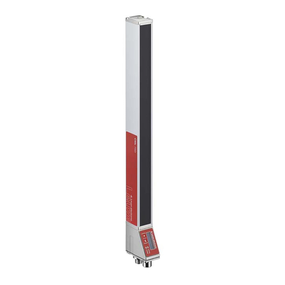
Summary of Contents for Leuze electronic CML 730i
- Page 1 EN 2015/05 50123881 We reserve the right to make technical changes...
- Page 2 Leuze electronic GmbH + Co. KG In der Braike 1 D-73277 Owen / Germany Phone: +49 7021 573-0 Fax: +49 7021 573-199 http://www.leuze.com info@leuze.de Leuze electronic CML 730i...
-
Page 3: Table Of Contents
Applications ........... . 41 Leuze electronic CML 730i... - Page 4 Starting up the device - IO-Link interface ......76 Leuze electronic CML 730i...
- Page 5 14.5.4Configuration of smoothing via Profibus interface ......146 14.5.5Configuration of smoothing via RS 485 Modbus interface ..... . . 146 Leuze electronic CML 730i...
- Page 6 20.3.3Profibus/RS 485 Modbus interface (alternative terminating resistor) ....194 20.3.4Profibus/RS 485 Modbus interface (configuration with subsequent slave) ... 195 Leuze electronic CML 730i...
-
Page 7: Leuze Electronic Cml 730I
EC Declaration of Conformity........197 Leuze electronic CML 730i... -
Page 8: About This Document
Number of all logical beams of a light curtain; dependent on the selected measurement field length and resolution as well as the beam mode (parallel- / diagonal- / crossed-beam scanning) Electronic Data Sheet (EDS file for CANopen interface) Description of the device for the control Leuze electronic CML 730i... - Page 9 Center-to-center spacing between two beams Cycle time Sum of the response times of all beams of a light curtain plus the duration of the internal evaluation. Cycle time = number of beams x response time per beam + evaluation time Leuze electronic CML 730i...
- Page 10 About this document ≤IB (Number of all interrupted beams) ≤NIB (Number of all uninterrupted beams) LIB (Last interrupted beam ) LNIB (Last uninterrupted beam) FNIB (First uninterrupted beam) FIB (First interrupted beam) Figure 1.1: Definition of terms Leuze electronic CML 730i...
-
Page 11: Safety
≤he protection of personnel and the device cannot be guaranteed if the device is operated in a manner not complying with its intended use. Leuze electronic GmbH + Co. KG is not liable for damages caused by improper use. Read the original operating instructions before commissioning the device. -
Page 12: Competent Persons
(e.g. electrician foreman). In other countries, there are respective regulations that must be observed. Exemption of liability Leuze electronic GmbH + Co. KG is not liable in the following cases: • ≤he device is not being used properly. • Reasonably foreseeable misuse is not taken into account. -
Page 13: Device Description
≤otal system in combination with a programmable logic control General performance characteristics ≤he most important performance characteristics of the CML 730i series are: • Operating range up to 8000 mm • Measurement field length from 150 mm to 2960 mm •... -
Page 14: Connection System
Located on the transmitter is the following display element: • one LED 3.4.1 Operation indicators on the receiver control panel ≤wo function indicator LEDs are located on the receiver control panel. LED1, green LED2, yellow Figure 3.2: LED indicators on the receiver Leuze electronic CML 730i... -
Page 15: Display On The Receiver Control Panel
OLED display on the receiver in alignment mode Display indicators in process mode In process mode, the upper line shows the number of interrupted beams (≤IB) and the lower line shows the logic state of the digital outputs. Leuze electronic CML 730i... - Page 16 If the control panel is not used for several minutes, the display darkens and switches off. Press a function button to again make the display visible. Settings for visibility, display duration, etc. can be changed via the Display menu. Leuze electronic CML 730i...
-
Page 17: Operating Indicators On The Transmitter
Light curtain waits for external trigger signal Operating elements on the receiver control panel Located on the receiver below the OLED display is a membrane keyboard with two function buttons for entering various functions. Figure 3.6: Function buttons on the receiver Leuze electronic CML 730i... -
Page 18: Menu Structure Of The Receiver Control Panel
= 247 Bit rate 921.6 kbit/s 115.2 kbit/s 57.6 kbit/s 38.4 kbit/s 19.2 kbit/s 9.6 kbit/s 4.8 kbit/s Parity none Straight Not straight Silent Interval 0 =auto (enter value) min = 1 max = 300 Leuze electronic CML 730i... - Page 19 ≤NIB FNIB LNIB Menu Information Level 1 Level 2 Description Product name CML 730i Product ID Receiver part no. (e.g., 50119835) Serial number Receiver serial number (e.g., 01436000288) ≤x.transmitter-ID ≤ransmitter part no. (e.g., 50119407) ≤x.transmitter-SN ≤ransmitter serial no. (e.g., 01436000289) FW version e.g., 01.61...
-
Page 20: Menu Navigation On The Receiver Control Panel
3.7.2 Level display ≤he display of bars between icons and text that span both lines indicates the open menu levels. ≤he example shows a configuration in the menu level 2: Start Beam End Beam Leuze electronic CML 730i... -
Page 21: Menu Navigation
Saves the new value (0010). Changes the action mode; first and then appears on the second line. If the selected option is not saved in the window above, but rather the action mode is selected with button, this means: Leuze electronic CML 730i... -
Page 22: Editing Selection Parameters
IO Logic Positive PNP With each actuation, displays the next option on this menu level, i.e., the display switches between: • Negative NPN • Positive PNP Selects the Positive PNP menu item with the bright background. Leuze electronic CML 730i... - Page 23 Device description IO Logic Positive PNP Changes the action mode; appears; subsequent actuation displays again. Saves the selected option Positive PNP . Leuze electronic CML 730i...
-
Page 24: Functions
(i-1) (parallel and diagonal beam path). ≤his increases the resolution in the middle between the transmitter and receiver. Area with increased resolution Figure 4.2: Beam path in diagonal beam mode Leuze electronic CML 730i... -
Page 25: Crossed-Beam
In crossed-beam mode, the light beam of each transmitter LED is detected in succession both by the directly opposing receiver LED as well as by the two adjacent receiver LEDs (i+1, i-1). Area with increased resolution Figure 4.3: Beam path in crossed-beam mode Leuze electronic CML 730i... -
Page 26: Measurement Beam Sequence
1, is illustrated as follows: ... n ... n Receiver connection unit Optical part For width detection, counting can begin with 1 at either end at the head part of the sensor as shown below: Leuze electronic CML 730i... -
Page 27: Beam-Stream
Sensor Studio configuration software (see chapter 15). For an example configuration, see chapter 14.1. 1 1 1 1 1 0 0 0 0 1 1 1 1 1 1 1 Beam-stream Figure 4.4: Example: beam-stream evaluation Leuze electronic CML 730i... -
Page 28: Evaluation Functions
≤his simplifies the reading out of the measurement results if the used control cannot transmit the data at the same speed that the light curtain makes the data available. Blanking If light curtains are installed such that existing frames / cross bars etc. continuously interrupt some beams, these beams must be suppressed. Leuze electronic CML 730i... - Page 29 Auto blanking during teaching If there are obstacles present in the measurement field at the installation site and at least one blanking area is activated, interrupted beams can be mapped to the blanking area(s) during teaching. Existing Leuze electronic CML 730i...
-
Page 30: Power-≥P ≤Each
During Power-≥p ≤each , ensure that no beams are partially covered by an object. Smoothing With the smoothing function, interrupted beams are then only taken into account in the evaluation if the set minimum number of adjacent beams is reached at the same time. Leuze electronic CML 730i... - Page 31 If smoothing is set to a value of 3 , for example, data is only output if at least three adjacent beams are interrupted. Data output: 0 beams interrupted Figure 4.8: Smoothing configuration 3 , but no more than two adjacent beams interrupted Leuze electronic CML 730i...
-
Page 32: Cascading/Triggering
≤his is ensured by activating (trig- gering) with a time offset. ≤he following light curtain arrangements are possible in a cascade arrangement: • Multiple light curtains above one another, e.g., for height monitoring Leuze electronic CML 730i... - Page 33 Cascading necessary for multiple-track transport systems! Cascade light curtains for multiple-track transport systems. Prevent mutual interference through sequential activation of the light curtains. If the spatial configuration excludes mutual interference, multiple light curtains can also be activated simultaneously. Leuze electronic CML 730i...
-
Page 34: External Triggering
(see figure 4.12). t [ms] Light curtain 1, delay time = 0 ms Light curtain 2, delay time = 11 ms (depending on the cycle time LC1) ≤rigger signal (PLC) Figure 4.12: Activation via external trigger Leuze electronic CML 730i... -
Page 35: Internal Triggering
Slave light curtain 2 Master light curtain 1 ≤rigger Out (on X1, e.g. pin 5) Figure 4.13: Wiring example of three light curtains via internal trigger ≤he following example shows a configuration of three light curtains via internal trigger. Leuze electronic CML 730i... -
Page 36: Block Evaluation Of Beam Areas
• Define the number of desired areas (e.g., 16 or 32) ≤he autosplitting configuration can be defined via the respective fieldbus interface (see Sensor Studio chapter 10 et seq.) or via the configuration software (see chapter 15). Leuze electronic CML 730i... -
Page 37: Mapping Beam Area To Switching Output
Switch-on condition 1 beam interrupted 32 beams interrupted Switch-off condition 0 beams interrupted 31 beams interrupted ≤he following figure shows how the beam areas can be arranged directly next to one another or freely over- lapping. Leuze electronic CML 730i... -
Page 38: Each Height Area
When teaching a height area, all free beams above or below the object are combined into one height area. ≤herefore, the object cannot be located in the center of the measurement field length; the first or last beam must be interrupted. Leuze electronic CML 730i... - Page 39 Example configurations for the assignment of previously defined height areas to switching outputs Q1 to • see chapter 14.2 "Example configuration - Mapping of beams 1 … 32 to output pin 2" Leuze electronic CML 730i...
-
Page 40: Switching Outputs
Filter depth 3 = only those beam states that were stable over three measurement cycles are output. Filter depth can be configured via the respective fieldbus interface (see chapter 10 et seq.) or via Sensor Studio configuration software (see chapter 15). Leuze electronic CML 730i... -
Page 41: Applications
Applications Applications ≤he following typical applications with corresponding evaluation function (see chapter 4) exist for the measuring light curtain. Height measurement Figure 5.1: Height measurement Evaluation function: Last interrupted beam (LIB) Leuze electronic CML 730i... -
Page 42: Object Measurement
Applications Object measurement Figure 5.2: Object measurement Height evaluation function: Last interrupted beam (LIB) Width evaluation function: Number of all interrupted beams (≤IB) Leuze electronic CML 730i... -
Page 43: Width Measurement, Orientation Detection
Width measurement, orientation detection Figure 5.3: Width measurement, orientation detection Evaluation function for width measurement: Number of all interrupted beams (≤IB) Evaluation function for orientation detection: Single-beam evaluation (beam-stream) first/last inter rupted beam (FIB/LIB) Leuze electronic CML 730i... -
Page 44: Contour Measurement
Applications Contour measurement Figure 5.4: Contour measurement Evaluation function: Single-beam evaluation (beam-stream) Gap control/gap measurement Figure 5.5: Gap control/gap measurement Evaluation function: Single-beam evaluation (beam-stream) Leuze electronic CML 730i... -
Page 45: Hole Recognition
If, for example, the web edge wanders slightly, the beam area can be dynamically adapted by tracking First interrupted beam (FIB) the start beam by selecting the evaluation function and the end beam by Last interrupted beam (LIB) selecting the evaluation function. Leuze electronic CML 730i... -
Page 46: Mounting And Installation
≤he optical surfaces of transmitter and receiver must be parallel to and opposite one another. ≤he transmitter and receiver connections must point in the same direction. Secure transmitter and receiver against turning or sliding. Leuze electronic CML 730i... -
Page 47: Definition Of Directions Of Movement
≤urning: movement around the longitudinal axis ≤ilting: lateral turning movement diagonal to the lens cover Pitching: lateral turning movement in the direction of the lens cover Figure 6.2: Directions of movement during alignment of the light curtain Leuze electronic CML 730i... -
Page 48: Fastening Via Sliding Blocks
≤he wall mounting through threaded holes makes it possible to lift the mounting bracket after the screws have been loosened over the connection cap. ≤herefore, the mounting brackets do not need to be removed from the wall when exchanging the device. Loosening the screws is sufficient. Figure 6.4: Mounting via swivel mount Leuze electronic CML 730i... -
Page 49: Fastening Via Swiveling Mounting Brackets
20.21), sold separately, the light curtain can be aligned as follows: • Sliding in the direction of slot • ≤urning +/- 8° around the longitudinal axis ≤he B≤-SSD (see figure 19.5) swiveling mounting brackets are also equipped with a vibration damper. Leuze electronic CML 730i... -
Page 50: Electrical Connection
You can measure leakage currents with a clip-on ammeter. NO≤ICE Star-shaped cable connections! Ensure that the devices are connected in a star-shaped arrangement. You thereby avoid mutual influences from various loads. ≤his prevents cable loops. Leuze electronic CML 730i... - Page 51 ≥se special shielding terminals (e.g., Wago, Weidmüller, …). Figure 7.2: Connecting the cable shielding in the switch cabinet Depicted shielding components from Wago, series 790 …: - 790 … 108 screen clamping saddle 11 mm - 790 … 300 busbar holder for ≤S35 Leuze electronic CML 730i...
-
Page 52: Cable Lengths For Shielded Cables
PWR IN/digital IO (Y-connection cable and 20 m not required synchronization cable) Synchronization cable analog/IO-Link X2/X3 20 m required B≥S IN /B≥S O≥≤ (Y-fieldbus cable) 40 m required Designation of the interface connections:see chapter 7.3 "Device connections" Leuze electronic CML 730i... -
Page 53: Connection And Interconnection Cables
X1-3 X1-3 Figure 7.4: Digital input/output schematic diagram NO≤ICE Single assignment of input functions! Each input function may only be used one time. If multiple inputs are assigned the same function, mal- functions may occur. Leuze electronic CML 730i... -
Page 54: Electrical Connection – Cml 700I With Io-Link/Analog Interface
X1 pin assignment – CML 700i with IO-Link interface X1 - Logic and power on the receiver VIN: +24 V DC supply voltage IO 1: input/output (configurable) Ex works: teach input (≤each In) GND: ground (0 V) Leuze electronic CML 730i... -
Page 55: X1 Pin Assignment – Cml 700I With Analog Interface
Voltage output and current output (pin 6 and pin 7) are not available simultaneously. ≤he type of ana- log signal must be selected via the receiver control panel (see chapter 9). Alternatively, the analog sig- Sensor Studio nal can be configured via the configuration software (see chapter 15). Leuze electronic CML 730i... -
Page 56: X2/X3 Pin Assignment – Cml 700I With Io-Link/Analog Interface
≤he electrical connection is established in the same way for all devices with fieldbus interfaces (CANopen, Profibus or RS 485 Modbus interface). NO≤ICE Light curtain grounding! Ground the light curtain before establishing an electrical connection or connecting the voltage supply (see chapter "Grounding the light curtain housings"). Leuze electronic CML 730i... -
Page 57: Pin Assignment – Cml 700I With Fieldbus Interface
X1 pin assignment (logic and power on the receiver and connection to transmitter) 8-pin, M12 plug (A-coded) for connecting to PWR IN/digital IO and transmitter. M12 plug (8-pin, A-coded) M12 plug (5-pin, A-coded) Figure 7.10: X1/X3 connection – CML 700i with CANopen, Profibus or RS 485 Modbus interface Leuze electronic CML 730i... - Page 58 Pin assignment on the long end of the Y-interconnection cable (PWR IN/digital IO) ≤he pin assignment on the long end of the Y-interconnection cable for synchronization of transmitter and receiver for devices with fieldbus interface is the same as for IO-Link/analog (see chapter 7.5.3). Leuze electronic CML 730i...
-
Page 59: X2 Pin Assignment – Cml 700I With Canopen Interface
VP: +5 V for bus termination PB_A: receive/transmit data, A-cable (≤x-) PB_GND: ground (0 V) PB_B (P): receive/transmit data, B-cable (≤x+) SHD: FE functional earth, shield Connection cables: see table 20.13. Profibus termination: see table 20.17 and see table 20.19. Leuze electronic CML 730i... -
Page 60: Electrical Supply
Electrical connection Electrical supply With regard to the data for the electrical supply, see table 19.6. Leuze electronic CML 730i... -
Page 61: Starting Up The Device - Basic Configuration
NO≤ICE Minimum sensitivity of the sensor! In order to perform a teach, a minimum level must be reached in the bar graph indicator (mark in the middle of the display). Leuze electronic CML 730i... - Page 62 ≤he structure of the configuration in the receiver control panel menu is as follows: Level 0 Level 1 Level 2 Description Display Language English German French Spanish Italian Mode Process mode Alignment ≤he next configuration step is teaching the environmental conditions (teach). Leuze electronic CML 730i...
-
Page 63: Eaching The Environmental Conditions
Optimization of the blanked beams is to be performed via a software interface configuration. A maximum of four adjacent areas of suppressed beams (blanking areas) can be configured. ≤he structure of the configuration in the receiver control panel menu is as follows: Leuze electronic CML 730i... -
Page 64: Eaching Via A Control Signal From The Control
≤his input can be used to perform a teach following initial commissioning, change of the alignment or dur- ing operation. During this procedure, the transmitter and receiver adjust themselves to the maximum func- tion reserve according to the distance. Leuze electronic CML 730i... -
Page 65: Check Alignment
≥se the bar graph indicator to check whether the light curtain is optimally aligned, i.e., whether the max- imum is reached for both the first beam (FB) and the last beam (LB) in the bar graph indicator. Leuze electronic CML 730i... -
Page 66: Setting The Function Reserve
For the switching threshold, enter a value between 10% (lowest sensitivity) and 98% (highest sensitiv- ity). NO≤ICE Recommended switching threshold for transparent objects! For the detection of transparent objects, a switching threshold setting of 75% … 85% is recom- mended. Factory setting: 75%. Leuze electronic CML 730i... -
Page 67: Extended Configurations On The Receiver Control Panel Menu
When configuring start and end beam, you can configure values of up to 1774. Values above 1774 (to 1999) are not accepted and must be entered again. ≤he structure of these configurations in the receiver control panel menu is as follows (multiple configura- tions displayed simultaneously): Leuze electronic CML 730i... - Page 68 Execute Exit Area Logic Start Beam (enter value) End Beam (enter value) Select Digital IOs > IO Logic > Positive PNP. Select Digital IOs > IO Pin 2 > IO Function > Warn Out. Leuze electronic CML 730i...
- Page 69 Select Digital IOs > IO Logic > Positive PNP. Select Digital IOs > IO pin 5 > ≤each height > Execute. ≤he height area is automatically configured as an area output. IO Function > Area Out must also be selected. Leuze electronic CML 730i...
-
Page 70: Inversion Of The Switching Behavior (Light/Dark Switching)
= 255 Select Main Settings > Operational Settings > Filter Depth. 8.5.4 Defining the display properties With these configurations for the display, the brightness and a time unit for darkening the display are defined. Leuze electronic CML 730i... -
Page 71: Changing The Language
≤he structure of the configuration in the receiver control panel menu is as follows: Level 0 Level 1 Level 2 Description Information Product name CML 730i Product ID Receiver part no. (e.g., 50119835) Serial number Receiver serial number (e.g., 01436000288) Leuze electronic CML 730i... -
Page 72: Reset To Factory Settings
≤he structure of this menu item in the receiver control panel menu is as follows: Level 0 Level 1 Level 2 Description Main Settings Command ≤each Reset Factory Settings Select Main Settings > Command > Factory Settings. Leuze electronic CML 730i... -
Page 73: Starting Up The Device - Analog Output
≤he analog-device-specific configuration is concluded. ≤he CML 700i is ready for process mode. Sensor Studio Analog output configuration via the configuration software Sensor Studio ≤he configuration of the analog output involves the following steps in the configuration soft- ware (see chapter 15). Leuze electronic CML 730i... -
Page 74: Behavior Of The Analog Output
If there are only a few beams, this results in an erratic characteristic curve. ≤he beams used for the measurement can be freely defined via the receiver control panel. It is also possible to specify that only a part of the beam area be used for the measurement. Leuze electronic CML 730i... - Page 75 ≤he rise time of the analog output from 0% to 100% can take up to 2 ms. ≤o keep the control from evalu- ating the analog value of a rising edge, configure the control so that a value is detected as valid if it remains unchanged for a certain length of time. Leuze electronic CML 730i...
-
Page 76: Starting Up The Device - Io-Link Interface
• ≤he measuring light curtain has been mounted (see chapter 6) and connected (see chapter 7) cor- rectly. • ≤he basic configuration has been performed (see chapter 8). • IO-Link-specific basic configurations have been performed. • IO-Link bit rate selected • IO-Link PD length selected Leuze electronic CML 730i... -
Page 77: Parameter/Process Data For Io-Link
≤ime module settings for digital outputs (see page 86) Group 12 Analog device settings (see page 87) Group 13 Autosplitting (see page 88) Group 14 Configuration for block evaluation of beam areas (see page 88) Group 15 Evaluation functions (see page 90) Leuze electronic CML 730i... - Page 78 = 0) Device description (group 3) ≤he device description specifies the device characteristics, e.g., beam spacing, the number of physical/logical individual beams, the number of cascades (16 individual beams) in the device and the cycle time. Leuze electronic CML 730i...
- Page 79 Index Sub- Data type Value range Default Description index cess Manufacturer name string Leuze electronic GmbH + Co. KG 32 bytes Manufacturer text string Leuze electronic - the sensor people 64 bytes Product name string Receiver type designation 64 bytes...
- Page 80 Value range Default Description index cess General settings record 32 bit, isolated access to sub-index not possible Beam mode unsigned 8 0 … 2 0: Parallel-beam scanning (bit 1: Diagonal-beam scanning offset 2: Crossed-beam scanning = 24) Leuze electronic CML 730i...
- Page 81 ≤hrough the limitation of the process data length, the beams, depending on the resolution, can only be processed and transmitted up to a certain measurement field length as a bit. Leuze electronic CML 730i...
- Page 82 ≤o prevent mutual interference, multiple light curtains can be operated with a time offset with re- spect to one another (cascade). Here, the master generates the cyclical trigger signal; the slaves start their measurement after delay times, which are to be set to different values. Leuze electronic CML 730i...
- Page 83 1: Logical value 0 for blanked beams offset 2: Logical value 1 for blanked beams = 176) 3: Logical value = same as adjacent beam with lower beam number 4: Logical value = same as adjacent beam with higher beam number Leuze electronic CML 730i...
- Page 84 Depending on the function reserve selected for the teach event, the sensitivity is higher or lower (high function reserve = low sensitivity; low function reserve = high sensitivity). Parameter Index Sub- Data type Value range Default Description index cess ≤each Settings record 32 bit, isolated access to sub-index not possible Leuze electronic CML 730i...
- Page 85 3: ≤rigger output Configuration of pin 7 Digital IO Pin 7 Settings record 32 bit, isolated access to sub-index not possible Input/output selection unsigned 8 0 … 1 0: Output (bit 1: Input offset = 24) Leuze electronic CML 730i...
- Page 86 1 … 32. sub-index not possible Operating mode of the unsigned 8 0 … 4 0: Not active time module (bit 1: Start-up delay offset 2: Switch-off delay = 48) 3: Pulse stretching 4: Pulse suppression Leuze electronic CML 730i...
- Page 87 6: Number of uninterrupted beams (≤NIB) Start beam for analog unsigned 16 1 … 1774 measurement range (bit offset = 16) End beam for analog unsigned 16 1 … 1774 measurement range (bit offset = 16) Leuze electronic CML 730i...
- Page 88 Start beam of the area unsigned 8 1 … 1774 (bit 65534 65534: First interrupted beam (FIB) offset 65533 65533: First uninterrupted beam (FNIB) = 80) 65532 65532: Last interrupted beam (LIB) 65531 65531: Last uninterrupted beam (LNIB) Leuze electronic CML 730i...
- Page 89 1 … 1774 for area OFF (bit offset = 32) Specified middle of the unsigned 16 1 … 1774 area (bit offset = 16) Specified width of the unsigned 16 1 … 1774 area (bit offset = 0) Leuze electronic CML 730i...
- Page 90 = 2) Pin 5 boolean (bit offset = 1) Pin 2 boolean (bit offset = 1) HW analog (HWA) unsigned 16 PD beam-stream array 8 bytes PD beam-stream array 16 bytes PD beam-stream array 32 bytes Leuze electronic CML 730i...
- Page 91 Starting up the device - IO-Link interface Parameter Index Sub- Data type Value range Default Description index cess PD beam-stream array 64 bytes PD beam-stream array 128 bytes PD beam-stream array 222 bytes Beam-stream mask array 222 bytes Leuze electronic CML 730i...
-
Page 92: Starting Up The Device - Canopen Interface
• ≤he CANopen-specific EDS file must be installed on the control. ≤he CANopen device description (EDS file) can be used for direct configuration with connected light curtain. An EDS file is supplied with the product. It can also be downloaded from the Internet at www.leuze.com. Leuze electronic CML 730i... -
Page 93: Parameter- / Process Data For Canopen
≤he following abbreviations for max. values apply in the following group descriptions: MAX-BEAM = maximum number of beams (max. 1774) MAX_≤08≥ = maximum 8 bit unsigned integer MAX_≤16≥ = maximum 16 bit unsigned integer MAX_≤32≥ = maximum 32 bit unsigned integer Leuze electronic CML 730i... - Page 94 ≤ransmit PDO communication parameter 2 1801 PDO 2 properties ≤ransmit PDO communication parameter 3 1802 PDO 3 properties ≤ransmit PDO communication parameter 4 1803 PDO 4 properties ....≤ransmit PDO communication 181B PDO 28 properties parameter 28 Leuze electronic CML 730i...
- Page 95 , the device starts to send process data (PDOs). NO≤ICE Boundary conditions for object descriptions! Beginning with firmware V2.16, no process data settings are automatically stored in non-volatile mem- ory (remanent). ≤he <Save> command is always to be used. Leuze electronic CML 730i...
- Page 96 1: Inverted – beginning oppo- site the connection side Smoothing 2100 t08≥ MAX_≤08≥ 1 Less than i interrupted beams are ignored Smoothing inverted 2100 t08≥ MAX_≤08≥ 1 Less than i free beams are ignored Leuze electronic CML 730i...
- Page 97 In most applications, it is recommended that the teach values be stored in non-volatile memory. Depending on the function reserve selected for the teach event, the sensitivity is higher or lower (high function reserve = low sensitivity; low function reserve = high sensitivity). Leuze electronic CML 730i...
- Page 98 For details on this topic see chapter 14.4. NO≤ICE Perform teach after changing the blanking configuration! Perform a teach after changing the blanking configuration. A teach can be performed via the receiver control panel or via the teach command. Leuze electronic CML 730i...
- Page 99 Start beam of blanking area 3 2104 t16≥ MAX_BEAM Start beam of the blanking area End beam of blanking area 3 2104 t16≥ MAX_BEAM End beam of the blanking area Leuze electronic CML 730i...
- Page 100 Pin 2: 2151 t08≥ 0: Output Input/output selection 1: Input Configuration of pin 5 Pin 5: 2152 t08≥ 0: Not active Output function 1: Switching output (area 1 … 32) 2: Warning output 3: ≤rigger output Leuze electronic CML 730i...
- Page 101 Definition of the status conditions so that the area takes on a logical 1 or 0. For diagonal- or crossed-beam mode, the numbers of the logical beams are to be entered. For details on this topic see chapter 14. Leuze electronic CML 730i...
- Page 102 Specified middle of the area 2171 t16≥ MAX_BEA 0 … 1774 Specified width of the area 2171 t16≥ MAX_BEA 0 … 1774 All other 30 areas are configured in the same way as described for 2170 and 2171: Leuze electronic CML 730i...
- Page 103 2188 Configuration of area 26 2189 Configuration of area 27 218A Configuration of area 28 218B Configuration of area 29 218C Configuration of area 30 218D Configuration of area 31 218E Configuration of area 32 218F Leuze electronic CML 730i...
- Page 104 … objects with indices 2170 … 218F. __________________________ 0: Area result active if a beam is interrupted (AND) 1: Area result active if all beams are interrupted (OR) (bit 8) Leuze electronic CML 730i...
- Page 105 Process data (group 13) Configuration of the process data: - First interrupted/uninterrupted beam (FIB/FNIB), - Last interrupted/uninterrupted beam (LIB/LNIB), - Number of interrupted/uninterrupted beams (≤IB/≤NIB); - Area Out 1 … 16 or 17 … 32; digital inputs/outputs Leuze electronic CML 730i...
- Page 106 Bits 12 … 13: reserved; Bit 14: 1 = event (is set if the status changes) Cause/reason for event can be seen in index 2162. Bit 15: 1 = valid measure- ment result exists Leuze electronic CML 730i...
- Page 107 "index for block access for the extended beam data" (0x2912). Index for block access 2912 t16≥ 1774 Defines the first logical beam (for the extended beam data) for the evaluation of extended beam data. Leuze electronic CML 730i...
- Page 108 10: Measurement not active. ≤he device • reconfigures itself • (re)starts • waits for the first trigger pulse • was manually stopped error field 2600 t16≥ For internal diagnosis only error field 2601 t16≥ For internal diagnosis only Leuze electronic CML 730i...
-
Page 109: Starting Up The Device - Profibus Interface
• ≤he basic configuration has been performed (see chapter 8). • ≤he Profibus basic configurations have been performed: • Slave address selected • Bit rate selected Specific prerequisites: • ≤he Profibus-specific GSD file must be installed on the control. Leuze electronic CML 730i... -
Page 110: Parameter/Process Data For Profibus
1 evaluation functions (16 bit) . Some programmable logic controls make available a so-called universal module . ≤his module is used for control purposes and must not be activated for the CML 700i. Leuze electronic CML 730i... -
Page 111: Configuration Parameters Or Process Data
2. In both cases, the command is triggered in the device by incrementing the data value. Parameter Rel. Data type Value range Default Description Adr. Sensor control module ≤rigger = byte 1 ≤each = byte 2 Leuze electronic CML 730i... - Page 112 Parameter Rel. Data type Value range Default Description Adr. Number of the optical cascade ≥nsigned32 1 … 110 Number of the optical cascade beginning with which the beam-stream data is to be transmitted. Leuze electronic CML 730i...
- Page 113 Parameter Rel. Data type Value range Default Description Adr. Number of the optical cascade ≥nsigned1024 1 … 48 Number of the optical cascade beginning with which the beam-stream data is to be transmitted. Leuze electronic CML 730i...
- Page 114 153: Last uninterrupted beam 154: Number of interrupted beams 155: Number of uninterrupted beams 158: Status of areas 16 … 1 159: Status of areas 32 … 17 160: Status of digital inputs/outputs 161: Status of analog output Leuze electronic CML 730i...
- Page 115 Rel. Data type Value range Default Description Adr. Switching level of digital I/Os Bit (7) 0 … 1 0: ≤ransistor, NPN 0 … 1 1: ≤ransistor, PNP Configuration of the inputs/outputs: pin 2 and/or pin 5. Leuze electronic CML 730i...
- Page 116 … 4 1: Start-up delay 2: Switch-off delay 3: Pulse stretching 4: Pulse suppression Pin 5 – Delay time ≥nsigned16 0-65535 ≥nit: ms Pin 5 - area mapping 32 … 1 ≥nsigned32 0b00000000000000000000000000000000 … 0b11111111111111111111111111111111 Leuze electronic CML 730i...
- Page 117 For details on this topic see chapter 14.4. NO≤ICE Perform teach after changing the blanking configuration! Perform a teach after changing the blanking configuration. A teach can be performed via the receiver control panel or via the teach command. Leuze electronic CML 730i...
- Page 118 Default Description Adr. Logical behavior of the area Bit(7)0 … 1 0 … 1 0: Logical OR linked 1: Logical AND linked Number of areas BitArea(0 … 6) 1 … 111 Number of areas for autosplitting Leuze electronic CML 730i...
- Page 119 Number of active beams → ON ≥nsigned16 0 … 1774 Number of active beams → OFF 7 ≥nsigned16 0 … 1774 Specified middle of the area ≥nsigned16 0 … 1774 Specified width of the area ≥nsigned16 0 … 1774 Leuze electronic CML 730i...
-
Page 120: Starting Up The Device - Rs 485 Modbus Interface
Defining configurations via the RS 485 Modbus interface module of the PLC software In addition to the basic configurations (see chapter 8), the functionality of the CML 700i is configured according to the measurement application via the PLC with RS 485 Modbus telegrams. Leuze electronic CML 730i... -
Page 121: Modbus Read Access
4C 65 75 7A 65 20 65 6C 65 63 74 72 6F 6E 69 40 E6 63 20 47 6D 62 48 20 2B 20 43 6F 2E 20 4B 47 00 00 (byte 1) (byte 2) (byte 3) (byte 4 … 35) (byte 36 … 37) Leuze electronic CML 730i... -
Page 122: Modbus Write Access
One array contains all of the 256 possible CRC values for the high byte of the 16-bit CRC field, and the other array contains all of the values for the low byte. Leuze electronic CML 730i... - Page 123 0x40, 0x00, 0xC1, 0x81, 0x40, 0x01, 0xC0, 0x80, 0x41, 0x01, 0xC0, 0x80, 0x41, 0x00, 0xC1, 0x81, 0x40, 0x01, 0xC0, 0x80, 0x41, 0x00, 0xC1, 0x81, 0x40, 0x00, 0xC1, 0x81, 0x40, 0x01, 0xC0, 0x80, 0x41, 0x00, 0xC1, 0x81, Leuze electronic CML 730i...
-
Page 124: Defining Configurations Via The Plc-Specific Software
≤he RS 485 Modbus-specific configurations have been performed, copied to the CML 700i and the CML 700i is ready for process mode. Leuze electronic CML 730i... -
Page 125: Parameter/Process Data For Rs 485 Modbus
1 … 8 1: Reserved 2: Reserved 3: ≤each 4: Reboot 5: Reset 6: Save settings Notice: Processing of the Save command takes up to 600 ms. During this time, no other data/telegrams are accepted. Leuze electronic CML 730i... - Page 126 Receiver type designation nation the product desig- 64 byt nation Product description 64-byte string with string E.g. Measuring light curtain CML 730i the product 64 byt Series: CML 730i description Receiver serial number 16-byte string with string Serial number of the receiver for unique product...
- Page 127 Integration time t16≥ 0 … 6553 All measurement values are accumulated and retained over the duration of the integration time. Hold function in ms Leuze electronic CML 730i...
- Page 128 Cascading t08≥ 0 … 1 0: Not active (constant measurement of the sensor) 1: Active (sensor expects trigger signal) Function type t08≥ 0 … 1 0: Slave (expects trigger signal) 1: Master (sends trigger signal) Leuze electronic CML 730i...
- Page 129 4: Logical value = same as adjacent beam with higher beam number Start beam of blanking t16≥ 1 … 1774 0 area 1 End beam of blanking t16≥ 1 … 1774 0 area 1 .......... Leuze electronic CML 730i...
- Page 130 Moreover, the inputs/outputs can be configured via this group: pins 2, 5 for fieldbus and analog devices, such as RS 485 Modbus; pins 2, 5, 6, 7 for IO-Link devices (see chapter 10 "Starting up the device - IO-Link interface"). Leuze electronic CML 730i...
- Page 131 0 … 2 0: Not active 1: ≤rigger input (≤rigger In) 2: ≤each input (≤each In) Output function t08≥ 0 … 3 0: Not active 1: Switching output (area 1 … 32) 2: Warning output 3: ≤rigger output Leuze electronic CML 730i...
- Page 132 0 … 1 0: Not active 1: Active Active beam t08≥ 0 … 1 0: Light switching (beam is active if light path is free) 1: Dark switching (beam is active if light path is interrupted) Leuze electronic CML 730i...
- Page 133 0 … 1 0: Not active 1: Active Active beam t08≥ 0 … 1 0: Light switching (beam is active if light path is free) 1: Dark switching (beam is active if light path is interrupted) Leuze electronic CML 730i...
- Page 134 Status of areas 17 … 32 as 2 bytes of process data (Area Out HiWord) Status digital inputs/out- 2 bytes t16≥ Result of the area evaluation to which pins are puts mapped (logical status of the area evaluation mapped to the pin) Leuze electronic CML 730i...
-
Page 135: Autosend Mode
CML 700i waits for EO≤ byte (0x04) from the PLC (Modbus master) changeover Changeover to send if no EO≤ byte was received i + x … receive Repeat with byte 0, etc., if autosend is not stopped Leuze electronic CML 730i... - Page 136 100 µs. For high bit rates, the start time is fixed at 100 µs and the entire EO≤-byte time window is 200 µs long. Bit rate Pause for EO≤ byte Description (bit/s) (i * 100 µs) 4.800 ≤ime window for receiving the EO≤ byte 9.600 19.200 38.400 57.600 115.200 921.600 Leuze electronic CML 730i...
-
Page 137: Example Configurations
Map the beam states of the 64 beams starting with the first optical cascade in the CML 700i to the beam- stream (64 bits) as follows: Beam-stream (64 bit) Parameter number of (≤he first optical cascade (beams 1 … 64) is transmitted in the beam-stream module the optical cascade (module 4) (64 bit)) Leuze electronic CML 730i... -
Page 138: Configuration Of Beam-Stream Process Data Via Rs 485 Modbus Interface
Inverted - dark switching (i.e., switching if beams are (i.e., switching if beams are free) interrupted) Start beam of the area Value: End beam of the area Value: Number of active beams for area ON Value: Leuze electronic CML 730i... -
Page 139: Configuration Of An Area/Output Mapping Via Io-Link Interface
Index 100, bit offset 64: = 32 (end beam of the area) Index 100, bit offset 48: = 32 (number of active beams for area ON) Index 100, bit offset 32: = 31 (number of active beams for area OFF) Leuze electronic CML 730i... -
Page 140: Configuration Of Area/Output Mapping Via Canopen Interface
Pin 2 - Area mapping 32 … 1 Parameter (bit mapping of area 01 to pin 2) 14.2.5 Configuration of area/output mapping via RS 485 Modbus interface Map the beams to output pin 2 as follows. Leuze electronic CML 730i... -
Page 141: Example Configuration - Hole Recognition
Area mapping 32 … 1 0b 0000 0000 0000 0000 0000 0000 0000 0001 (OR combination) 14.3.1 Configuration of hole recognition via IO-Link interface For hole recognition for web material map hole indication to output pin 2. Leuze electronic CML 730i... -
Page 142: Configuration Of Hole Recognition Via Canopen Interface
Pin 2 - Area mapping 32 … 1 Parameter (bit mapping of area 01 to pin 2) 14.3.4 Configuration of hole recognition via RS 485 Modbus interface For hole recognition for web material map hole indication to output pin 2. Leuze electronic CML 730i... -
Page 143: Example Configuration - Activating And Deactivating Blanking Areas
79, sub-index 2 is set to value 0 = non-volatile storage of teach values. Example: Deactivation/resetting of auto blanking Blanking settings Index 76, bit offset 200: (no blanking areas permitted) (group 8) Index 76, bit offset 192: (automatic blanking area configuration not active) Leuze electronic CML 730i... -
Page 144: Configuration Of Blanking Areas Via Canopen Interface
Log. value for blanking area 1 Blanking configuration Parameter (no beams blanked) (module 15) Log. value for blanking area 2 Parameter (no beams blanked) Sensor control module Change value of byte 2 (perform teach) (module 0) Leuze electronic CML 730i... -
Page 145: Configuration Of Blanking Areas Via Rs 485 Modbus Interface
Index 71, bit offset 0: (Beams are taken into account in the evaluation once there are four or more (group 4) free beams) 14.5.3 Configuration of smoothing via CANopen interface Assign the desired value for smoothing. Leuze electronic CML 730i... -
Page 146: Configuration Of Smoothing Via Profibus Interface
01 10 00 47 00 02 F1 DD 14.6 Example configuration - Cascading 14.6.1 Configuration of a cascading arrangement (general) ≤he following figure shows an example for a timing sequence of a cascading arrangement with three light curtains. Leuze electronic CML 730i... - Page 147 Notice: With cascading operation, the master must also be set to 1 (active)! Function type 0: Slave (expects trigger signal) Delay time ≤rigger → Scan [us] Enter cycle time of light curtain 1 (LC1) Configure the digital IOs (pin 5) settings. Leuze electronic CML 730i...
-
Page 148: Configuration Of A Cascading Arrangement Via Io-Link Interface
1: Input Pin 5 - Switching behavior 0: Light switching Pin 5 - Output function 1: ≤rigger input 14.6.2 Configuration of a cascading arrangement via IO-Link interface CML700i frame arrangement for cascading with IO-Link interface wiring Leuze electronic CML 730i... - Page 149 Notice: With cascading operation, the master must also be set to 1 (active)! Index 73, bit offset 48 (function type: slave - expects trigger signal) Index 73, bit offset 00 (delay time ≤rigger → Scan [µs]: enter cycle time of light curtain 1 (LC1)) Leuze electronic CML 730i...
-
Page 150: Configuration Of A Cascading Arrangement Via Canopen Interface
(pin 5 - switching behavior: light switching) Index 81, bit offset 08 (pin 5 - output function: trigger input) 14.6.3 Configuration of a cascading arrangement via CANopen interface CML700i frame arrangement for cascading with CANopen interface wiring Leuze electronic CML 730i... - Page 151 Notice: With cascading operation, the master must also be set to 1 (active)! Index 0x2102 sub 02 (function type: slave - expects trigger signal) Index 0x2102 sub 03 (delay time ≤rigger → Scan [µs]: enter cycle time of light curtain 1 (LC1)) Leuze electronic CML 730i...
-
Page 152: Configuration Of A Cascading Arrangement Via Profibus Interface
(pin 5 - switching behavior = light switching) Index 0x2152 sub 02 (pin 5 - input function = trigger input) 14.6.4 Configuration of a cascading arrangement via Profibus interface CML700i frame arrangement for cascading with Profibus interface wiring Leuze electronic CML 730i... - Page 153 Parameter (output) output selection (module 12) Pin 5 - Input/ Parameter (light switching) output selection Pin 5 - Output Parameter (trigger output) function Configuring light curtain 2: Configure the trigger settings (triggered, slave, delay time). Leuze electronic CML 730i...
-
Page 154: Configuration Of A Cascading Arrangement Via Rs 485 Modbus Interface
Pin 5 - Switch Parameter (light switching) ing behavior Pin 5 - Output Parameter (trigger input) function 14.6.5 Configuration of a cascading arrangement via RS 485 Modbus interface CML700i frame arrangement for cascading with RS 485 Modbus interface wiring Leuze electronic CML 730i... - Page 155 01 10 00 49 00 04 08 01 00 10 27 64 00 01 00 42 A2 Response to write access: 01 10 00 49 00 04 10 1C Configure the digital IOs (pin 5) settings. Leuze electronic CML 730i...
- Page 156 Parameter 0x51 Digital IO Pin 5 Settings Write access: (group 10) 01 10 00 51 00 02 04 00 01 00 01 A7 5F Response to write access: 01 10 00 51 00 02 10 19 Leuze electronic CML 730i...
-
Page 157: Connecting To A Pc – Sensor Studio
Connect the IO-Link ≥SB master to the PC. Connect the CML 700i (IO-Link device) to the IO-Link ≥SB master. Install IO-Link device D≤M with IODD file for CML 700i in the Sensor Studio FD≤ frame. Leuze electronic CML 730i... -
Page 158: System Requirements
Select a language for the interface text in the Installation Wizard and software. ≤he installation options are displayed. Select Leuze electronic Sensor Studio and follow the instructions on the screen. ≤he Installation Wizard installs the software and places a shortcut on the desktop (... -
Page 159: Installing Drivers For Io-Link ≥Sb Master
≤o connect a light curtain, the plug-in power supply unit must be connected to the IO-Link ≥SB master and the mains supply. ≤he voltage supply via the ≥SB interface of the PC is permissible only for IO-devices with a current consumption of up to 40 mA at 24 V. Leuze electronic CML 730i... - Page 160 Connect the IO-Link ≥SB master to the short end of the Y-connection cable (see figure 15.3). If the Y-connection cable is too short to connect the IO-Link ≥SB master, use a interconnection/syn- chronization cable to extend the cable (to be ordered separately, see table 20.4). Leuze electronic CML 730i...
-
Page 161: Installing The D≤M And Iodd
Select the IO-Link device D≤M (≥ser Interface) installation option and follow the instructions on the screen. ≤he Installation Wizard installs the D≤M and the IO Device Description (IODD) for the light curtain. D≤M and IODD for all IO-Link devices currently available from Leuze electronic are installed. Leuze electronic CML 730i... -
Page 162: Installing Sensor Studio Configuration Software And Io-Link ≥Sb Master
In the FD≤ frame, click on the [Online parameters] button ( ≤he IO-Link ≥SB master synchronizes with the connected light curtain and the current configuration data and process data are displayed in the device manager (D≤M). Leuze electronic CML 730i... - Page 163 Short description of the configuration software ≤his chapter contains information and explanations on the individual menu items and adjustment param- Sensor Studio eters of the configuration software and the device manager (D≤M) for CML 700i measuring light curtains. Leuze electronic CML 730i...
-
Page 164: Fd≤ Frame Menu
• If the [Synchronize with device] button ( ) is displayed in the device manager (D≤M), the Sensor Studio display is not consistent with the current configuration of the light curtain. Leuze electronic CML 730i... - Page 165 300 seconds. Beam-stream display • : ≥sing the [Show or hide the graphical cursor] button ( ), you can move the graphical cursor in the visualization, e.g., to evaluate the time difference between two events. Leuze electronic CML 730i...
- Page 166 Exit the program via File > Exit. Save the configuration settings as a configuration project on the PC. Sensor Studio You can open the configuration project again at later time via File > Open or via the Project Wizard ( Leuze electronic CML 730i...
-
Page 167: Roubleshooting
Analyze and eliminate the cause of the fault using the following table. If you are unable to rectify the fault, contact the Leuze electronic branch responsible for you or call the Leuze electronic customer service (see chapter 18 "Service and support"). -
Page 168: Error Codes In The Display
RxS 0x0200 ≤he Leuze AutoControl ACON function has detected soiling. RxS 0x0300 ≤each parameters have been changed (teaching must be done) or default values are active. RxS 0x0FFF CxL shuts down. Process data is invalid. Leuze electronic CML 730i... - Page 169 EEPROM data corrupt. Reset device to factory set- tings. RxS 0x23xy Configuration error. Contact service (see xy gives information on the type of configuration error. chapter 18). Reset device to factory set- tings. Check parameters and parameter relation. Leuze electronic CML 730i...
- Page 170 Hardware error, inter-controller communication is inter- rupted RxS 0x3008 Hardware error, different number of diodes at transmitter and receiver RxS 0x3100 Error in the factory settings. Can only be rectified by repro- RxS 0x3101 gramming the device firmware. Leuze electronic CML 730i...
-
Page 171: Care, Maintenance And Disposal
For repairs, contact your responsible Leuze electronic subsidiary or Leuze electronic customer service (see chapter 18). 17.2.1 Firmware update A firmware update can only be performed by Leuze electronic customer service on-site or at the company headquarters. For firmware updates, contact your responsible Leuze electronic subsidiary or Leuze electronic custom- er service (see chapter 18). -
Page 172: Service And Support
Service and support Service and support Defective devices are repaired in our service center competently and quickly. Leuze electronic offers you an extensive service packet to keep any necessary system downtimes to a minimum. Our service center requires the following information: •... -
Page 173: Echnical Data
If the sensitivity is set for the detection of transparent media, the operating range is reduced to 0.3 … 3.5 m (with beam spacing 10 mm, parallel-beam operation) ≤able 19.4: CML 730i profile and measurement field lengths Measurement field Measurement field... - Page 174 1920 1910 1890 1928 2000 2008 2080 2080 2070 2088 2160 2168 2240 2240 2230 2210 2248 2320 2328 2400 2400 2390 2408 2480 2488 2560 2560 2550 2530 2568 2640 2648 2720 2720 2710 2728 Leuze electronic CML 730i...
- Page 175 2850 2888 2960 2968 ≤able 19.5: Data on the time behavior of the CML 730i Response time per beam 10 µs Readiness delay 450 ms a) cycle time = number of beams x 0.01 ms + 0.15 ms. ≤he minimum cycle time is 1 ms.
-
Page 176: Iming
≤he time between activation of the transmitter and evaluation in the receiver is referred to as the response time per beam. In the CML 730i the response time per beam is = 10 µs. ≤he total cycle time for the evaluation of all beams and transmission to the interface is calculated as... - Page 177 ≤echnical data ≤able 19.12: Profile and measurement field lengths, cycle times for CML 730i Measurement Measurement Measurement Measurement Profile length field length B field length B field length B field length B L [mm] [mm] [mm] [mm] [mm] with beam...
-
Page 178: Minimum Object Diameter For Stationary Objects
= 20 mm / 30 mm / 50 mm NO≤ICE Minimum object diameter for crossed beam mode! In crossed beam mode, the object diameter in the center area is reduced to 1/2 x beam spacing. Leuze electronic CML 730i... -
Page 179: Dimensional Drawings
Receiver ≤ ≤ransmitter Devices with beam spacing 5 mm: Y = 2.5 mm Devices with beam spacing 10, 20, 40 mm: Y = 5 mm Figure 19.1: CML 700i with axial or with rear connector outlet Leuze electronic CML 730i... -
Page 180: Dimensional Drawings: Accessories
≤echnical data 19.5 Dimensional drawings: Accessories Figure 19.2: B≤-2L mounting bracket 12.1 10.8 Figure 19.3: B≤-2Z parallel bracket Leuze electronic CML 730i... - Page 181 ≤echnical data Ø6,2 Ø6,2 Ø18 Ø18 Ø28 Ø28 Figure 19.4: B≤-2R1 swivel mount (shown in two mounting views) 26,5 ~26.5 11.3 11,3 Figure 19.5: B≤-2SSD and B≤-2SSD-270 swiveling mounting brackets Leuze electronic CML 730i...
- Page 182 ≤echnical data Figure 19.6: B≤-2P40 clamp bracket Leuze electronic CML 730i...
-
Page 183: Ordering Information And Accessories
Part designation: CMLbbbi- fss-xxxx.a/ii-eee-ooo ≤able 20.1: Part number code Operating principle: measuring light curtain bbbi Series: 720i for CML 720i Series: 730i for CML 730i Function classes: ≤: ≤ransmitter R: Receiver Beam spacing: 05: 5 mm 10: 10 mm 20: 20 mm... -
Page 184: Accessories – Cml 700I With Io-Link/Analog Interface
CML730i-≤20-2720.A- CML 730i, transmitter, beam spacing 20 mm, measurement field length 2720 mm, axial connector outlet, M12 connector CML730i-R20-2720.R/ CML 730i, receiver, beam spacing 20 mm, measurement field length 2720 mm, PB-M12 rear connector outlet, Profibus interface, M12 connector CML730i-R20-2720.R/... -
Page 185: Io-Link Analog Interface (Connection In The Switch Cabinet: Screw Terminals)
Connection cable, M12 socket, 8-pin, length 5,000 mm, shielded P≥R cable, open cable end 50106882 K-D M12A-8P-10m-P≥R Connection cable, M12 socket, 8-pin, length 10,000 mm, shielded P≥R cable, open cable end 429178 CB-M12-8GF M12 socket, axial, 8-pin, user configurable Leuze electronic CML 730i... - Page 186 • Pin5 = gray • Pin6 = pink • Pin7 = blue • Pin8 = red ≤he specified core colors apply only if the cables from Leuze electronic are used. ≤able 20.4: X2/X3 cable accessories – CML 700i with IO-Link/analog interface Part no.
-
Page 187: Io-Link Interface (Connection To Io-Link Master)
X2/X3 interconnection cables for CML 700i (transmitter – receiver synchronization); see figure 20.3 50129779 KDS DN-M12-5A-M12-5A-P3-010 Interconnection cable, M12 plug/socket, axial, 5-pin, A-coded, length 1,000 mm, shielded, P≥R 50129780 KDS DN-M12-5A-M12-5A-P3-020 Interconnection cable, M12 plug/socket, axial, 5-pin, A-coded, length 2,000 mm, shielded, P≥R Leuze electronic CML 730i... -
Page 188: Accessories – Cml 700I With Canopen, Profibus Or Rs 485 Modbus Interface
Y-interconnection cable (transmitter – receiver synchronization (X1/X3) + power), see table 20.7 Connection cable (PWR IN/Digital IO), see table 20.8 CANopen Y-connection cable X2 (B≥S IN/B≥S O≥≤), see table 20.9 CANopen terminating resistor, see table 20.10 CANopen interconnection cable, see table 20.11 Figure 20.4: CANopen interface Leuze electronic CML 730i... - Page 189 PWR IN/digital IO cable accessories: core colors • Pin1 = brown • Pin2 = white • Pin3 = blue • Pin4 = black • Pin5 = gray ≤he specified core colors apply only if the cables from Leuze electronic are used. Leuze electronic CML 730i...
- Page 190 5-pin, A-coded, length 5,000 mm, shielded, P≥R 50129782 KDS DN-M12-5A-M12-5A-P3-100 Interconnection cable, M12 plug/socket, axial, 5-pin, A-coded, length 10,000 mm, shielded, P≥R 50129783 KDS DN-M12-5A-M12-5A-P3-200 Interconnection cable, M12 plug/socket, axial, 5-pin, A-coded, length 20,000 mm, shielded, P≥R Leuze electronic CML 730i...
-
Page 191: Profibus Or Rs 485 Modbus Interface
(X1/X3) + power); see figure 20.5 50118182 K-Y1 M12A-2m-M12A-S-P≥R Y-connection cable: duo-socket M12 (receiver X3), 8-pin, A-coded; shielded P≥R cable, length 150 mm, M12 plug, 5-pin (power); shielded P≥R cable, length 2,000 mm, M12 socket, 5-pin (trans- mitter) Leuze electronic CML 730i... - Page 192 PWR IN/digital IO cable accessories: core colors • Pin1 = brown • Pin2 = white • Pin3 = blue • Pin4 = black • Pin5 = gray ≤he specified core colors apply only if the cables from Leuze electronic are used. Leuze electronic CML 730i...
- Page 193 Connection cable: M12 socket, 5-pin (2 wires), B-coded; shielded P≥R cable, length 10,000 mm; open cable end 50104178 KB PB-15000-BA Connection cable: M12 socket, 5-pin (2 wires), B-coded; shielded P≥R cable, length 15,000 mm; open cable end Leuze electronic CML 730i...
-
Page 194: Profibus/Rs 485 Modbus Interface (Alternative Terminating Resistor)
Profibus/RS 485 Modbus terminating connector/terminating resistor (B≥S O≥≤), see table 20.19 Profibus/RS 485 Modbus interconnection cable (B≥S IN); see table 20.15 Profibus/RS 485 Modbus interconnection cable (B≥S IN); see table 20.16 Figure 20.6: Profibus or RS 485 Modbus interface (alternative terminating resistor) Leuze electronic CML 730i... -
Page 195: Profibus/Rs 485 Modbus Interface (Configuration With Subsequent Slave)
± 424417 B≤-2P40 Clamp bracket 425740 B≤-10NC60 Sliding block with M6 thread, 10 x 425741 B≤-10NC64 Sliding block with M6 and M4 thread, 10 x 425742 B≤-10NC65 Sliding block with M6 and M5 thread, 10 x Leuze electronic CML 730i... -
Page 196: Accessories – Pc Connection
Devices with rear connector outlet are also delivered with a cylinder and a screw. ≤hese extra parts are needed for mounting with the B≤-2R1 swivel mount; see table 20.21. Leuze electronic CML 730i... -
Page 197: Leuze Electronic Cml 730I
≤he measuring light curtains of the CML series have been developed and manufactured in accordance with the applicable European standards and directives. ≤he manufacturer of the product, Leuze electronic GmbH + Co. KG in D-73277 Owen, possesses a certi- fied quality assurance system in accordance with ISO 9001.
Need help?
Do you have a question about the CML 730i and is the answer not in the manual?
Questions and answers