Sign In
Upload
Manuals
Brands
Leuze electronic Manuals
Accessories
CML 730i
Leuze electronic CML 730i Manuals
Manuals and User Guides for Leuze electronic CML 730i. We have
1
Leuze electronic CML 730i manual available for free PDF download: Original Operating Instructions
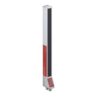
Leuze electronic CML 730i Original Operating Instructions (197 pages)
Measuring light curtain
Brand:
Leuze electronic
| Category:
Accessories
| Size: 3.5 MB
Table of Contents
Table of Contents
3
Leuze Electronic CML 730I
7
1 About this Document
8
2 Safety
11
Competent Persons
12
3 Device Description
13
Connection System
14
Display on the Receiver Control Panel
15
Operating Indicators on the Transmitter
17
Menu Structure of the Receiver Control Panel
18
Menu Navigation on the Receiver Control Panel
20
Menu Navigation
21
Editing Selection Parameters
22
4 Functions
24
Crossed-Beam
25
Measurement Beam Sequence
26
Beam-Stream
27
Evaluation Functions
28
Power-≥P ≤Each
30
Cascading/Triggering
32
External Triggering
34
Internal Triggering
35
Block Evaluation of Beam Areas
36
Mapping Beam Area to Switching Output
37
Each Height Area
38
Switching Outputs
40
5 Applications
41
Object Measurement
42
Width Measurement, Orientation Detection
43
Contour Measurement
44
Hole Recognition
45
6 Mounting and Installation
46
Definition of Directions of Movement
47
Fastening Via Sliding Blocks
48
Fastening Via Swiveling Mounting Brackets
49
7 Electrical Connection
50
Cable Lengths for Shielded Cables
52
Connection and Interconnection Cables
53
Electrical Connection – CML 700I with IO-Link/Analog Interface
54
X1 Pin Assignment – CML 700I with Analog Interface
55
X2/X3 Pin Assignment – CML 700I with IO-Link/Analog Interface
56
Pin Assignment – CML 700I with Fieldbus Interface
57
X2 Pin Assignment – CML 700I with Canopen Interface
59
Electrical Supply
60
8 Starting up the Device - Basic Configuration
61
Eaching the Environmental Conditions
63
Eaching Via a Control Signal from the Control
64
Check Alignment
65
Setting the Function Reserve
66
Extended Configurations on the Receiver Control Panel Menu
67
Inversion of the Switching Behavior (Light/Dark Switching)
70
Changing the Language
71
Reset to Factory Settings
72
9 Starting up the Device - Analog Output
73
Behavior of the Analog Output
74
10 Starting up the Device - IO-Link Interface
76
Parameter/Process Data for IO-Link
77
11 Starting up the Device - Canopen Interface
92
Parameter- / Process Data for Canopen
93
12 Starting up the Device - Profibus Interface
109
Parameter/Process Data for Profibus
110
Configuration Parameters or Process Data
111
13 Starting up the Device - RS 485 Modbus Interface
120
Modbus Read Access
121
Modbus Write Access
122
Defining Configurations Via the PLC-Specific Software
124
Parameter/Process Data for RS 485 Modbus
125
Autosend Mode
135
14 Example Configurations
137
Configuration of Beam-Stream Process Data Via RS 485 Modbus Interface
138
Configuration of an Area/Output Mapping Via IO-Link Interface
139
Configuration of Area/Output Mapping Via Canopen Interface
140
Example Configuration - Hole Recognition
141
Configuration of Hole Recognition Via Canopen Interface
142
Example Configuration - Activating and Deactivating Blanking Areas
143
Configuration of Blanking Areas Via Canopen Interface
144
Configuration of Blanking Areas Via RS 485 Modbus Interface
145
Configuration of Smoothing Via Profibus Interface
146
Configuration of a Cascading Arrangement Via IO-Link Interface
148
Configuration of a Cascading Arrangement Via Canopen Interface
150
Configuration of a Cascading Arrangement Via Profibus Interface
152
Configuration of a Cascading Arrangement Via RS 485 Modbus Interface
154
Connecting to a PC – Sensor Studio
157
15 Connecting to a PC - Sensor Studio
158
System Requirements
158
Installing Drivers for IO-Link ≥SB Master
159
Installing the D≤M and IODD
161
Installing Sensor Studio Configuration Software and IO-Link ≥SB Master
162
FD≤ Frame Menu
164
Roubleshooting
167
Error Codes in the Display
168
17 Care, Maintenance and Disposal
171
18 Service and Support
172
Echnical Data
173
Iming
176
Minimum Object Diameter for Stationary Objects
178
Dimensional Drawings
179
Dimensional Drawings: Accessories
180
20 Ordering Information and Accessories
183
Accessories – CML 700I with IO-Link/Analog Interface
184
IO-Link Analog Interface (Connection in the Switch Cabinet: Screw Terminals)
185
IO-Link Interface (Connection to IO-Link Master)
187
Accessories – CML 700I with Canopen, Profibus or RS 485 Modbus Interface
188
Profibus or RS 485 Modbus Interface
191
Profibus/Rs 485 Modbus Interface (Alternative Terminating Resistor)
194
Profibus/Rs 485 Modbus Interface (Configuration with Subsequent Slave)
195
Accessories – PC Connection
196
Leuze Electronic CML 730I
197
Advertisement
Advertisement
Related Products
Leuze electronic CU411-RS4
Leuze electronic CML 720i Ex
Leuze electronic CML 720i
Leuze electronic CMS708i-ENC1-0800-0960
Leuze electronic CMS708i-ENC1-0640-0800
Leuze electronic CMS708i-ENC1-0560-0960
Leuze electronic CMS748i-ENC1-0640-0720
Leuze electronic CMS748i-ENC1-0640-0640
Leuze electronic CR55M2/R2
Leuze electronic CR 55 Series
Leuze electronic Categories
Accessories
Barcode Reader
Measuring Instruments
Security Sensors
Scanner
More Leuze electronic Manuals
Login
Sign In
OR
Sign in with Facebook
Sign in with Google
Upload manual
Upload from disk
Upload from URL