Table of Contents
Advertisement
Quick Links
Thank you for choosing our product.
To ensure the best performance of this product, please read this user guide fully and carefully before
using it and keep this manual together with the product for future reference as needed.
4K@60/HDCP 2.2 HDMI Switcher
IDK Corporation
IMP-400UHD
<User Guide>
Ver.2.2.0
Advertisement
Table of Contents

Subscribe to Our Youtube Channel
Related Manuals for IDK IMP-400UHD


Summary of Contents for IDK IMP-400UHD
- Page 1 4K@60/HDCP 2.2 HDMI Switcher IMP-400UHD <User Guide> Ver.2.2.0 Thank you for choosing our product. To ensure the best performance of this product, please read this user guide fully and carefully before using it and keep this manual together with the product for future reference as needed.
- Page 2 Oracle and Java are trademarks of Oracle Corporation its subsidiaries, and affiliated companies in the United States and other countries. The terms Anti-snow and Connection Reset are registered trademarks of IDK Corporation in Japan. All other company and product names mentioned in this manual are either registered trademarks or...
- Page 3 Some information contained in this User guide such as exact product appearance, diagrams, menu operations, communication commands, and so on may differ depending on the product version. This User guide is subject to change without notice. You can download the latest version from IDK’s website at: http://www.idkav.com...
- Page 4 IMP-400UHD User Guide Safety Instructions Read and understand all safety and operating instructions before using this product. Follow all instructions and cautions as detailed in this document. Enforcement Symbol Description Indicates the presence of a hazard that may result in death or serious...
- Page 5 ● Do not repair, modify or disassemble. Since the product includes circuitry that uses potentially lethal, high voltage levels, disassembly by unauthorized personnel may lead to the risk of fire or electric shock. For internal inspection or repair, contact your IDK Do not representative.
- Page 6 Unplug If you continue to use the product under these conditions, it may increase the risk of electrical shock or fire. For maintenance and repair, contact your IDK representative. ● Unplug immediately if water or other objects are directed inside.
- Page 7 IMP-400UHD User Guide Caution ■ For installing and connecting products: ● Do not place the product in a location where it will be subjected to high temperatures. If the product is subjected to direct sunlight or high temperatures while under operation, it may affect the product’s performance and reliability and may increase the risk of fire.
-
Page 8: Table Of Contents
IMP-400UHD User Guide Table of Contents Included Items ............................11 Product Outline ............................12 Features ..............................13 Panels ............................... 14 Front panel ............................14 Rear panel ............................15 Application example ..........................16 Precautions ............................... 17 Attaching Rubber feet .......................... 17 Installation ............................ - Page 9 IMP-400UHD User Guide 8.2.6 Switching interval of sequence switching mode ................53 8.2.7 Input detection ..........................53 8.2.8 Start channel of sequence switching mode ................54 Input settings ............................55 8.3.1 Non-signal input monitoring ......................56 8.3.2 Input HDCP settings ........................57 Output settings .............................
- Page 10 IMP-400UHD User Guide 9.2.4 The number of TCP-IP connections .................... 91 10 Product Specification ..........................92 11 Troubleshooting ............................94...
-
Page 11: Included Items
IMP-400UHD User Guide 1 Included Items Ensure that all items illustrated below are included in the package. If any items are missing or damaged, please contact IDK. One (1) main unit (IMP-400UHD) One (1) AC adapter with screw lock Five (5) cable clamps... -
Page 12: Product Outline
IMP-400UHD User Guide 2 Product Outline The IMP-400UHD is a 4x1 HDMI signal switcher supporting 4K@60 video signal and HDCP2.2 (hereafter referred to as “IMP”). Digital audio signal is converted into analog and output from the AUDIO OUTPUT connector. Settings can be set remotely using RS-232C and LAN ports. -
Page 13: Features
IMP-400UHD User Guide 3 Features ■ Video ・ Up to 4K@60 (4:4:4) ・ HDCP 1.4/2.2 ・ HDR ・ 3D ・ x.v.Color ・ Transmission distances 1080p@60 : Up to 98 ft. (30 m) 4K@60 : Up to 39 ft. (12 m) (when cable supporting 18 Gbps transmission is used) ・... -
Page 14: Panels
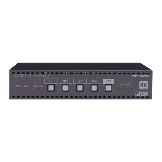
IMP-400UHD User Guide 4 Panels 4.1 Front panel ① ② ③ ④ ⑤ [Fig. 4.1] Front panel drawing [Table 4.1] Front panel features Feature Description ① POWER LED Shows power status of the IMP. Illuminating (green) : Powered ON. Does not illuminate : Powered OFF. -
Page 15: Rear Panel
IMP-400UHD User Guide 4.2 Rear panel ④ ⑧ ⑦ ⑨ ⑥ ⑤ ⑩ ⑪ ② ③ ① [Fig. 4.2] Rear panel drawing [Table 4.2] Rear panel features Feature Description ① HDMI input connectors For HDMI and DVI signals to interface source devices, such as Blu-ray players ②... -
Page 16: Application Example
IMP-400UHD User Guide 5 Application example Source and sink devices are connected to the IMP. Power output Contact input Tally output Controller Speakers 4K Monitor Power amplifier HDMI/DVI Up to 39 ft. (12 m)* Analog audio HDMI/DVI HDMI/DVI HDMI/DVI HDMI/DVI Up to 39 ft. -
Page 17: Precautions
・ Do not block vent holes. To provide adequate ventilation, maintain sufficient clearances around the IMP, 1.2 in. (30 mm) or more. ・ When the IMP needs to be mounted in an enclosed space or an EIA rack without using IDK’s rack mounting hardware (RM-44S, RM-44D, and RM-SH), ensure that a sufficient ventilation/cooling system is provided to keep the ambient temperature at 104°F (40°C) or lower. -
Page 18: Cabling
IMP-400UHD User Guide 6.3 Cabling When connecting the to external devices, please observe the following precautions. ・ Read manuals for the external devices. ・ Before you connecting cables to the IMP or an external device, dissipate static electricity by touching grounded metal such as racks before handling signal cables. -
Page 19: Cables
IMP-400UHD User Guide 6.3.1 Cables If the video is 4K format, the TMDS data rate (transmission speed) is 18 Gbps at maximum. If a high-speed HDMI cable, the TMDS data rate becomes 10.2 Gbps at maximum, and video cannot be displayed stably. -
Page 20: Connecting Audio Cables
IMP-400UHD User Guide 6.3.2 Connecting audio cables Connect the audio cable to the 5-pin terminal block, and then insert the 5-pin terminal block into the appropriate port on the IMP’s rear panel. The IMP supports both balanced and unbalanced analog signals. -
Page 21: Power Output/Contact Input/Tally Output
IMP-400UHD User Guide 6.3.4 5V Power output/Contact input/Tally output The IMP has contact input/tally output connector as external control interface which enables control from PC’s I/O board and remote operation from a switch box. A 5V power output connector is included for Tally LED. - Page 22 IMP-400UHD User Guide ■ Controlling contact input Input channel of the IMP can be switched remotely by using contact input. Please ground the contact input terminal of the desired input channel to switch the input channel. After the GND is connected, keep it back to the open state. If using a press-type switch to control contact input, select a toggle type switch (pressing: ON;...
- Page 23 IMP-400UHD User Guide ■ Controlling Tally output In order to illuminate the LED of the selected input channel selection key, form the circuit as follows. 5V OUT 5V OUT 1-pin 3-pin 300Ω 500mA IN1 T IN1 T IN2 T IN2 T...
-
Page 24: Ac Adapter With Screw Locking Mechanism
IMP-400UHD User Guide 6.3.5 AC adapter with screw locking mechanism The shapes of AC plugs with screw locking mechanism vary from country to country. The AC plug can be removed from the AC adapter. Removing AC plug: Slide the AC plug (②) from the AC adapter while holding down the portion mentioned below (①). -
Page 25: Basic Operation
IMP-400UHD User Guide 7 Basic Operation The IMP can be controlled from input channel selection buttons, WEB menu, or communication commands. In this chapter, basic operations using input channel selection buttons and WEB menu. For communication command control, see chapters 9 and 10. -
Page 26: Operation From Input Channel Selection Key
IMP-400UHD User Guide 7.1 Operation from input channel selection key ・ Selecting input channels ・ Locking and Unlocking input channel selection keys ・ Setting sequence switching mode ・ Changing EDID resolution ・ Initializing settings Tip: You will hear a short beep tone when pressing available keys (by default). -
Page 27: Locking And Unlocking Input Channel Selection Keys
IMP-400UHD User Guide 7.1.2 Locking and Unlocking input channel selection keys Press and hold “IN1” for 3 seconds or longer to lock/unlock input channel selection keys. Press and hold “IN 1” for 3 seconds or longer to lock keys. When a key is locked, you hear a long beep tone and the LOCK LED lights green. -
Page 28: Setting Sequence Switching Mode
All settings will be reset to Factory default values by powering on the IMP while pressing and holding the “OFF” key. Press and hold the “OFF” key until you hear a long beep sound. Note that once settings are initialized, they cannot be restored again. 【See: 7.4 Factory default】 Hold OFF key and Power on IMP-400UHD [Fig. 7.4] Initialization... -
Page 29: Web Menu Operation
JavaScript is used for WEB browser. When you set the IMP from WEB browser menu, enable JavaScript before setting up. Refer to each browser’s help menu if you do not know how to enable JavaScript. Tip: IDK tests the IMP under the following environment: : Windows 7 Professional WEB browser : Microsoft Internet Explorer 11... -
Page 30: Starting Web Menu
IMP-400UHD User Guide 7.2.1 Starting WEB menu Enter the set IP address into the address bar in order to display the WEB menu. 【See: 8.9.2 Setting IP address】 【See: 8.9.1 Setting TCP port number】 [Table 7.3] Values to be typed... -
Page 31: How To Use Web Menu
IMP-400UHD User Guide 7.2.2 How to use WEB menu Menu Sub-menu [Fig. 7.7] WEB menu ① Select the desired menu. The setting items will be displayed in the submenu. ② For some menus, you can select channels by clicking the desired tab. -
Page 32: Selecting Input Channels
IMP-400UHD User Guide 7.2.3 Selecting input channels Select output channels from [CROSS POINT] > [CHANNEL SELECT]. Click the “OFF” button to disable video and audio signal output. Outputs IN1 input signals Disables output [Fig. 7.8] Selecting input channel Tip: Once the input channel with HDCP is selected, the HDCP authentication status of the channel is kept. -
Page 33: Locking And Unlocking Input Channel Selection Keys
IMP-400UHD User Guide 7.2.4 Locking and Unlocking input channel selection keys [CROSS POINT] > [OPERATION LOCK] Click [OPERATION LOCK] to lock front keys. The button will light green. Operations cannot be performed from the keys while they are locked; except for [IN1] for unlocking the keys. -
Page 34: Setting Sequence Switching Mode
IMP-400UHD User Guide 7.2.5 Setting sequence switching mode [CROSS POINT] > [SEQUENCE MODE] Input channel can be switched automatically at the desired interval. Click [SEQUENCE MODE] to switch input channels according to the [AUTO SWITCHING] settings. The button will light green. -
Page 35: Changing Name Of Input Channel Selection Buttons
IMP-400UHD User Guide 7.2.6 Changing name of input channel selection buttons [CROSS POINT] > [NAME EDIT] > [NAME EDIT] You can change names of [IN1] to [IN4] and [OUT] buttons. video-1 VIDEO_2 Video3 video 4 ① Click [NAME EDIT] ② Enter the desired name... -
Page 36: Setting Automatic Reload Time Of Web Menu
IMP-400UHD User Guide 7.2.8 Setting automatic reload time of WEB menu [OTHERS] > [AUTO RELOAD TIME] [OFF] : Not reloaded the WEB menu automatically [Default] [1] to [10] sec. : Reloaded the WEB menu automatically at the selected interval [Fig. 7.13] Setting automatic reload time... -
Page 37: Backing Up/Restoring Settings
[OTHERS] > [BACKUP/RESTORE] Click [BACKUP] to save the settings. After the message is displayed, click [OK]. The settings will be saved as “imp-400uhd.idm”. Click [Choose File] to select the desired file and click [RESTORE]. Click [OK] on the completion message. -
Page 38: Initialization
IMP-400UHD User Guide 7.2.10 Initialization Initializing settings other than LAN setting: [OTHERS] > [INITIALIZE] > [NORMAL INITIALIZE] Click [OK] on the confirmation message. Initializing all settings including LAN setting: [OTHERS] > [INITIALIZE] > [ALL INITIALIZE] Click [OK] on the confirmation message. -
Page 39: Displaying Version
IMP-400UHD User Guide 7.2.11 Displaying version You can view the model name and firmware version from [OTHERS] > [VERSION]. [Fig. 7.16] Displaying version Communication Command @GIV Version... -
Page 40: Connecting To Non-4K-Compliant Source Device
IMP-400UHD User Guide 7.3 Connecting to non-4K-compliant source device If connecting to a source device that does not support 4K, video may not be output because the built-in EDID is set to “2160p@60 (3840x2160) 4:4:4” by default. Change the EDID in order to output HDMI signals format channel selection keys, WEB menu, or commands. - Page 41 IMP-400UHD User Guide ■ Changing EDID resolution Selecting “2160p@60 (3840x2160) 4:4:4”: Press the desired flashing input channel selection key. Selecting “1080p@60 (1920x1080)”: Press the desired turned-on input channel selection key. Changing EDID Flashing Turned-ON 1080p@60(1920x1080) 2160p@60(3840x2160) 4:4:4 [Fig. 7.19] Changing EDID resolution Tip: To select a resolution other than “2160p@60 (3840x2160) 4:4:4”...
-
Page 42: Operation From Web Menu
IMP-400UHD User Guide ■ Disabling EDID changing mode Click the “OFF” key, you will hear a beep tone. Click “OFF” key [Fig. 7.20] Disabling EDID changing mode Tip: If you do not operate these keys for 10 seconds, the EDID changing mode will be disabled. -
Page 43: Factory Default
IMP-400UHD User Guide 7.4 Factory default [Table 7.6] Factory default (1/2) Setting Factory default Switching settings Priority of input channel automatic switching Masking time after automatic switching 0 m sec. Video to be output when input channel is changed OFF... - Page 44 IMP-400UHD User Guide [Table 7.7] Factory default (2/2) Setting Factory default EDID Speaker configuration NUMBER FL/FR : ON : OFF : OFF RL/RR : OFF : OFF FLC/FRC : OFF RLC/RRC : OFF FLW/FRW : OFF FLH/FRH : OFF : OFF : OFF ―...
-
Page 45: Settings
IMP-400UHD User Guide 8 Settings 8.1 WEB menu You can set I/O, EDID, communication, and other settings from [MENU]. [Fig. 8.1] WEB menu [Table 8.1] WEB menu and setting [ MENU ] Description Page ・ Selecting input channels CROSS POINT 32 to 35 ・... -
Page 46: Switching Settings
IMP-400UHD User Guide 8.2 Switching settings You can set switching between automatic input channel mode and sequence switching mode from [AUTO SWITCHING]. [Fig. 8.2] AUTO SWITCHING menu ■ Automatic input channel switching [Table 8.2] Sub menu and feature Sub menu... -
Page 47: Priority Of Input Channel Automatic Switching
IMP-400UHD User Guide 8.2.1 Priority of input channel automatic switching AUTO SWITCHING → AUTO SWITCHING ON (OFF to ON) Menu AUTO SWITCHING → AUTO SWITCHING OFF (ON to OFF) Setting value OFF : Input switching priority OFF [Default] 1 to 4 : Input switching priority 1 (Highest) to 4 (Lowest) - Page 48 IMP-400UHD User Guide The priority (PRI*) is not the same: IN 1 IN 2 IN 3 IN 4 PRI 1 PRI 2 PRI 3 PRI 4 PRI 1 PRI 2 PRI 3 PRI 4 Input signal Input signal Input signal Input signal “ON”...
- Page 49 IMP-400UHD User Guide The priority (PRI*) is the same: IN 1 IN 2 IN 3 IN 4 PRI 1 PRI 1 PRI 1 PRI 1 PRI 1 PRI 1 PRI 1 PRI 1 Input signal Input signal Input signal Input signal “ON”→“OFF”...
-
Page 50: Masking Time After Automatic Switching
IMP-400UHD User Guide 8.2.2 Masking time after automatic switching AUTO SWITCHING → AUTO SWITCHING MASK Menu Setting value 0 to 999999: 0 m sec. to 999999 m sec. [Default] 0 m sec. Communication Command @GMT / @SMT Masking time after automatic switching of input channel You can set the masking time that is from when input channel is switched automatically to when the next automatic switching is executed. -
Page 51: Sequence Switching Mode
IMP-400UHD User Guide 8.2.4 Sequence switching mode AUTO SWITCHING → SEQUENCE MODE Menu Setting value OFF : Disable [Default] ON : Enable Input channel can be switched automatically at the desired interval. Communication Command @GST / @SST Sequence switching mode You can disable/enable sequence switching mode. - Page 52 IMP-400UHD User Guide IN1, IN3, and IN4 are targets to be switched Interval: 10 seconds Example1 Switching starts from: The current input channel (NOW CHANNEL) The current channel: IN3 10 sec. 10 sec. 10 sec. 10 sec. Time Starting sequence switching mode Switching channel IN3 is included in the target channel →...
-
Page 53: Target Channels For Sequence Switching Mode
IMP-400UHD User Guide 8.2.5 Target channels for sequence switching mode AUTO SWITCHING → SEQUENCE CHANNEL Menu Setting value ON : To be switched [Default] OFF : Not to be switched Communication Command @GSQ / @SSQ Target channel for sequence switching mode You can set each input channel to be switched or not for when sequence switching mode is enabled. -
Page 54: Start Channel Of Sequence Switching Mode
IMP-400UHD User Guide 8.2.8 Start channel of sequence switching mode AUTO SWITCHING → SEQUENCE VIDEO STARTCH Menu Setting value NOW CHANNEL : Starts with the current input channel [Default] FIRST CHANNEL : Starts with the lowest number channel of target channels... -
Page 55: Input Settings
IMP-400UHD User Guide 8.3 Input settings You can set input settings from [INPUT SETTING]. [Fig. 8.8] INPUT SETTING menu [Table 8.5] Sub menu and feature Sub menu Feature Page INPUT VIDEO DETECT Non-signal input monitoring HDCP INPUT ENABLE Input HDCP settings... -
Page 56: Non-Signal Input Monitoring
IMP-400UHD User Guide 8.3.1 Non-signal input monitoring INPUT SETTING → INPUT VIDEO DETECT Menu Setting value OFF : Not monitoring ON : Monitoring 2000 to 15000 by 100 ms: 2 sec. to 15 sec. [Default] 10 sec. Communication Command @GDT / @SDT No-signal-input monitoring If you change the EDID settings of the IMP or power the IMP on/off, the source device may not output a video signal. -
Page 57: Input Hdcp Settings
IMP-400UHD User Guide 8.3.2 Input HDCP settings INPUT SETTING → HDCP INPUT ENABLE Menu Setting value HDCP 2.2 : Supports HDCP 2.2 and HDCP 1.4 [Default] HDCP 1.4 : Supports HDCP 1.4 DISABLE : Not support HDCP Communication Command @GHE / @SHE HDCP input enabled/disabled Some source equipment negotiates with the connected device to determine if it supports HDCP encryption. -
Page 58: Output Settings
IMP-400UHD User Guide 8.4 Output settings [Fig. 8.12] OUTPUT SETTING menu [Table 8.6] Sub menu and feature Sub menu Feature Page OUTPUT MODE Output mode OUTPUT HDMI MODE Checking Sink device’s EDID HDCP AUTHORIZATION HDCP re-authentication... -
Page 59: Output Mode
IMP-400UHD User Guide 8.4.1 Output mode OUTPUT SETTING → OUTPUT MODE Menu Setting value AUTO : Automatic [Default] DVI MODE : DVI output HDMI RGB MODE : RGB output HDMI YCbCr4:2:0 MODE: YCbCr 4:2:0 output HDMI YCbCr4:2:2 MODE: YCbCr 4:2:2 output... -
Page 60: Checking Sink Device's Edid
IMP-400UHD User Guide 8.4.2 Checking Sink device’s EDID OUTPUT SETTING → OUTPUT HDMI MODE Menu Setting value : EDID cannot be read, DVI signal will be output [Default] ERROR1 : EDID cannot be read, HDMI (without SCDC) signal will be output... -
Page 61: Audio Settings
IMP-400UHD User Guide 8.5 Audio settings [Fig. 8.13] AUDIO menu [Table 8.7] Sub menu and feature Sub menu Feature Page OUTPUT MUTE Mute 8.5.1 Mute AUDIO → OUTPUT MUTE Menu Setting value ON : Mute ON OFF : Mute OFF [Default]... -
Page 62: Contact Input
IMP-400UHD User Guide 8.6 Contact input [Fig. 8.14] CONTACT menu [Table 8.8] Sub menu and feature Sub menu Feature Page CHATTERING FILTER Chattering reduction 8.6.1 Chattering reduction CONTACT → CHATTERING FILTER Menu Setting value 0 to 300: 0 ms to 300 ms [Default] 30 ms... -
Page 63: Edid
IMP-400UHD User Guide 8.7 EDID [Fig. 8.16] EDID menu [Table 8.9] Sub menu and feature Sub menu Feature Page PC RESOLUTION EDID resolution DEEP COLOR INPUT Deep Color AUDIO FORMAT Audio format SPEAKER Speaker configuration MONITOR EDID COPY Copying EDID... -
Page 64: Edid Resolution
IMP-400UHD User Guide 8.7.1 EDID resolution EDID → PC RESOLUTION Menu Setting value [Table 8.10] EDID’s maximum resolution Communication Command @GVF / @SVF EDID You can set or customize EDID to be sent to the source device. Change the setting as needed. - Page 65 IMP-400UHD User Guide [Fig. 8.17] EDID’s maximum resolution (Cont’d) Upper: Max. resolution Spec. Remarks Setting value Lower: Pixels 1080i(1920x1080) 1080i 1920x1080 HDTV 1080p@30(1920x1080) 1080p (24/25/30) 1920x1080 VESA1080(1920x1080) VESA1080 VESA (RB), for DVI device input 1920x1080 1080p@60(1920x1080) 1080p (50/59.94/60) HDTV 1920x1080...
- Page 66 IMP-400UHD User Guide [Table 8.11] Maximum resolution and supported pixels Pixels Max. resolution - - - - - - - - - - - - - - - - - - - - - - - - - - - -...
-
Page 67: Deep Color
IMP-400UHD User Guide 8.7.2 Deep Color EDID → DEEP COLOR INPUT Menu Setting value 24-BIT COLOR: 24 bit/pixel (8 bit/component) [Default] 30-BIT COLOR: 30 bit/pixel (10 bit/component) 36-BIT COLOR: 36 bit/pixel (12 bit/component) Communication Command @GDI / @SDI Deep Color input You can set the Deep Color (Color depth) that is output from the source device. -
Page 68: Speaker Configuration
IMP-400UHD User Guide 8.7.4 Speaker configuration EDID → SPEAKER Menu Setting value [Table 8.13] Default speaker configuration Communication Command @GSP / @SSP The number of speakers You can set the speaker configuration of multi-channel audio. When the number of speakers is changed, the speaker configuration is set to the value shown in “[Table 8.13] Default speaker configuration”... -
Page 69: Copying Edid
IMP-400UHD User Guide 8.7.5 Copying EDID EDID → MONITOR EDID COPY Menu Communication Command @RME EDID copy EDID of the sink device is loaded and registered to the IMP. The EDID can be treated as a built-in EDID. -
Page 70: Rs-232C
IMP-400UHD User Guide 8.8 RS-232C [Fig. 8.19] RS-232C menu [Table 8.14] Sub menu and feature Sub menu Feature Page BAUD RATE Setting Baud rate DATA BIT LENGTH Setting data bit length PARITY Setting parity check STOP BIT Setting stop bit 8.8.1 Setting Baud rate... -
Page 71: Setting Data Bit Length
IMP-400UHD User Guide 8.8.2 Setting data bit length RS-232C → DATA BIT LENGTH Menu Setting value 8: 8 bit [Default] 7: 7 bit Communication Command @GCT / @SCT RS-232C 8.8.3 Setting parity check RS-232C → PARITY Menu Setting value NONE [Default]... -
Page 72: Lan
IMP-400UHD User Guide 8.9 LAN [Fig. 8.20] LAN menu [Table 8.15] Sub menu and feature Sub menu Feature Page PORT NUMBER Setting TCP port number IP ADDRESS Setting IP address SUBNET MASK Setting Subnet mask MAC ADDRESS Displaying MAC address 8.9.1 Setting TCP port number... -
Page 73: Setting Ip Address
IMP-400UHD User Guide 8.9.2 Setting IP address LAN → IP ADDRESS Menu Setting value 192.168.1.199 [Default] Communication Command @GIP / @SIP IP address 8.9.3 Setting Subnet mask LAN → SUBNET MASK Menu Setting value 255.255.255.0 [Default] Communication Command @GSB / @SSB Subnet mask 8.9.4 Displaying MAC address... -
Page 74: Startup Settings
IMP-400UHD User Guide 8.10 Startup settings [Fig. 8.21] POWER ON SETTING menu [Table 8.17] Sub menu and feature Sub menu Feature Page STARTUP CHANNEL Start-up input channel OPERATION LOCK Keylock at startup... -
Page 75: Start-Up Input Channel
IMP-400UHD User Guide 8.10.1 Start-up input channel POWER ON SETTING → STARTUP CHANNEL Menu Setting value IN1 to IN4 : Channel 1 to 4 : Channel OFF LAST CHANNEL : Last channel [Default] Communication Command @GMU / @SMU Startup input channel You can set an input channel for when the IMP is powered on. -
Page 76: Other Settings
IMP-400UHD User Guide 8.11 Other settings Buzzer and version display functions are explained in this section. See “7.2 Web menu operation” for other settings. [Fig. 8.22] Others [Table 8.20] Sub menu and feature Sub menu Feature Page BUZZER Buzzer tone... -
Page 77: Displaying Version
IMP-400UHD User Guide 8.11.2 Displaying version OTHERS → VERSION Menu Communication Command @GIV Version You can display the IMP firmware version. -
Page 78: Displaying Status (Web Menu)
IMP-400UHD User Guide 8.12 Displaying status (Web menu) [Fig. 8.23] Displaying status menu [Table 8.21] Sub menu and feature Sub menu Feature Page INPUT STATUS Input signal status MONITOR STATUS Sink device status ERROR STATUS Displaying error message EDID STATUS... -
Page 79: Input Signal Status
IMP-400UHD User Guide 8.12.1 Input signal status [Fig. 8.24] Input signal status (Example: IN1 and IN2) STATUS → INPUT STATUS Menu Values to be acquired [Table 8.22] Input video signal format Communication Command @GSS Displaying input signal status/sink device status You can display the input signal status that is input from an HDMI input connector. - Page 80 IMP-400UHD User Guide [Table 8.24] HDCP Item Value Description HDCP HDCP 2.2 Type0 HDCP 2.2 stream type 0 signal is input. HDCP 2.2 Type1 HDCP 2.2 stream type 1 signal is input. HDCP 1.4 HDCP 1.4 signal is input. NOT ENCRYPTED Signal that is not protected by HDCP is input.
- Page 81 IMP-400UHD User Guide [Table 8.28] Sampling frequency of input audio signal Item Value Description SAMPLING 48kHz Sampling frequency FREQUENCY (32/44.1/48/88.2/96/176.4/192kHz) is displayed. [Table 8.29] The number of input audio channels Item Value Description CHANNEL 2 CHANNEL 2-channel audio is input.
-
Page 82: Sink Device Status
IMP-400UHD User Guide 8.12.2 Sink device status [Fig. 8.25] Sink device status STATUS → MONITOR STATUS Menu Values to be acquired [Table 8.32] HDCP authentication status Communication Command @GSS Displaying input signal status/sink device status You can display information of the sink device that is connected to an HDMI output connector. -
Page 83: Displaying Error Message
IMP-400UHD User Guide 8.12.3 Displaying error message [Fig. 8.26] Error message STATUS → ERROR STATUS Menu Values to be acquired [Table 8.35] Error message Communication Command @GSS Displaying input signal status/sink device status [Table 8.35] Error message Item Value Description... - Page 84 IMP-400UHD User Guide [Table 8.37] Analog audio error message Item Value Description ANALOG AUDIO Audio Mute “8.5.1 Mute” is set to “ON”. ERROR Not DDC Power No source device is connected. No Signal No audio signal is input. AV Mute Received Audio output of source device is muted.
-
Page 85: Displaying Sink Device Edid
IMP-400UHD User Guide 8.12.4 Displaying sink device EDID [Fig. 8.27] Displaying sink device EDID STATUS → EDID STATUS Menu Values to be acquired [Table 8.38] EDID of sink device Communication Command @GES Monitor’s EDID You can display EDID of the sink device that is connected to an HDMI output connector. - Page 86 IMP-400UHD User Guide [Table 8.39] EDID of sink device (Cont’d) Item Value to be displayed Example Remarks - PCM CHANNEL 1 CHANNEL to 2 CHANNEL 8 CHANNEL COMPRESSD Supported/ Supported If compressed audio is AUDIO Not Supported supported, “Supported” is displayed.
-
Page 87: Communication Specification And Setup
IMP-400UHD User Guide 9 Communication Specification and Setup This chapter explains specifications and setting procedures of RS-232C communication and LAN. Refer to the command guide for communication command specifications. 9.1 RS-232C communication 9.1.1 Connecting RS-232C cable See “6.3.3 Connecting RS-232C cable” for connecting RS-232C cables. -
Page 88: Setting Up Rs-232C Communication
IMP-400UHD User Guide 9.1.3 Setting up RS-232C communication Follow the procedure below to set RS-232C communication between the IMP and control devices. (1) Connect the IMP and the control device via an appropriate cable. (2) Set the RS-232C communication as follows: ・... -
Page 89: Lan Communication
IMP-400UHD User Guide 9.2 LAN communication 9.2.1 LAN connector specification It supports Auto MDI/MDI-X, which distinguishes/switches straight and cross cables automatically. Pin assignments of LAN connector: Lights in green while link is established. Lights in orange if the send/receive Blinks in green while data is being rate is 100 Mbps. -
Page 90: Setting Up Lan Communication
IMP-400UHD User Guide 9.2.3 Setting up LAN communication Follow the procedure below to set LAN communication between the IMP and control devices. (1) Connect the IMP and the control device via a LAN cable. (2) Set up LAN communication as follows: ・... - Page 91 IMP-400UHD User Guide 9.2.4 The number of TCP-IP connections The IMP supports up to eight simultaneous TCP-IP connections (eight logical ports). To maintain optimal system accessibility, it is advisable to issue “port-open” and “port-close” commands before and after command or query strings are issued. This approach enables eight or more control devices to be effectively interfaced simultaneously and without concern for communication errors.
- Page 92 IMP-400UHD User Guide 10 Product Specification Item Description 4 inputs/HDMI Deep Color (*1)/DVI 1.0 (HDCP 1.4/2.2) - HDR (*2) - 3D (*3) Number/Signal - x.v.Color - TMDS single link HDMI/DVI - TMDS clocks: 25 MHz to 300 MHz - TMDS data rate: 0.75 Gbps to 18 Gbps...
- Page 93 ・4K@60:18 Gbps hi-speed transmission cable was used and signals of 4K@60 24 bit/pixel (8 bit/component) was input or output. The maximum distance depends on connected devices. If IDK’s cable is not used, video may be interrupted or may not be output even within the mentioned range.
- Page 94 IMP-400UHD User Guide 11 Troubleshooting This chapter recommends what to do if you have problems operating the IMP. In case the IMP does not work correctly, please check the following items first. ・ Are the IMP and all devices plugged in and powered on normally? ・...
- Page 95 IMP-400UHD User Guide Problem Cause/Check item/Solution Page Video is not output. [1] The set time for monitoring no-signal input may be too short. [2] Check if the selected input resolution is supported by the sink device. ・ If you select 1080i, video may not be output to sink devices that do not support interlaced signal.
- Page 96 IMP-400UHD User Guide Problem Cause/Check item/Solution Page ― Video is reduced Some sink devices display input video on the full screen regardless vertically or of aspect ratio. Check the display setting of the sink device. horizontally. Since some resolutions are always displayed on the full screen, change the output resolution of the source device.
- Page 97 IMP-400UHD User Guide Problem Cause/Check item/Solution Page ●Audio output (Cont’d) ・ Error code 9: ― Audio is not output. Set “8.4.1 Output mode” to a mode other than “DVI MODE”. If the sink device does not support HDMI signal, theIMP outputs DVI signal automatically.
- Page 98 IMP-400UHD User Guide Problem Cause/Check item/Solution Page ●Audio output (Cont’d) Compressed audio Compressed audio input is set to OFF (EDID settings) by factory (such as Dolby default. If using compressed audio, change the EDID setting. Digital, DTS) is not In order to output compressed audio of multi-channel, set the output from the number of speakers.
- Page 99 IMP-400UHD User Guide User Guide of IMP-400UHD Ver.2.2.0 Issued on: 5 June 2019 IDK Corporation Headquarters 7-9-1 Chuo, Yamato-shi, Kanagawa-pref. 242-0021 JAPAN TEL: +81-46-200-0764 FAX: +81-46-200-0765 Email: idk_eng@idk.co.jp URL: http: //www.idkav.com IDK America Inc. 72 Grays Bridge Road Suite 1-C, Brookfield, CT 06804 TEL: +1-203-204-2445 Email: sales@idkav.com URL: http: //www.idkav.com...
Need help?
Do you have a question about the IMP-400UHD and is the answer not in the manual?
Questions and answers