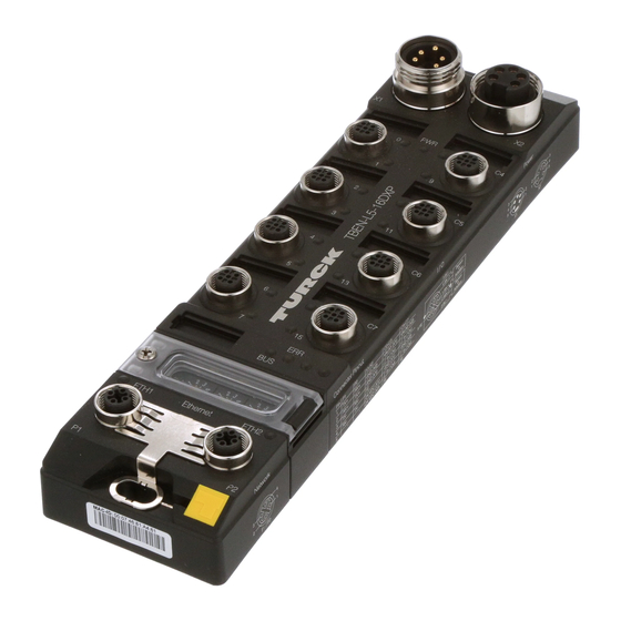
Table of Contents About these Instructions........................ 7 Target groups........................ 7 Explanation of symbols used .................. 7 Other documents ...................... 7 Feedback about these instructions................ 7 Notes on the Product ......................... 8 Product identification..................... 8 Scope of delivery ...................... 8 Legal requirements...................... 8 Manufacturer and service ....................
Page 4
Executing USB functions ...................... 111 9.3.3 USB functions – behavior of the RUN-LED in case of an error ........ 113 Hans Turck GmbH & Co. KG | T +49 208 4952-0 | F +49 208 4952-264 | more@turck.com | www.turck.com...
Page 5
Operating the device with the web server ............ 113 9.4.1 Changing the web server password .................. 113 9.4.2 Manage data node points from CODESYS symbol table.......... 114 10 Troubleshooting .......................... 116 11 Maintenance............................ 117 11.1 Executing the firmware update................ 117 11.1.1 Executing the firmware update via USB storage medium........... 117 11.1.2 Carry out firmware update via FDT/DTM ................
Page 6
Table of Contents Hans Turck GmbH & Co. KG | T +49 208 4952-0 | F +49 208 4952-264 | more@turck.com | www.turck.com...
This symbol denotes actions that the user must carry out. RESULTS OF ACTION This symbol denotes relevant results of actions. Other documents Besides this document the following material can be found on the Internet at www.turck.com: Data sheet Operating instructions EU Declaration of Conformity...
For further inquiries in Germany contact the Sales and Service Team on: Sales: +49 208 4952-380 Technology: +49 208 4952-390 Outside Germany, please contact your local Turck representative. Hans Turck GmbH & Co. KG | T +49 208 4952-0 | F +49 208 4952-264 | more@turck.com | www.turck.com...
The product is designed according to state-of-the-art technology. However, residual risks still exist. Observe the following warnings and safety notices to prevent damage to persons and property. Turck accepts no liability for damage caused by failure to observe these warning and safety notices.
CANopen and connect it to a system that is networked with PROFINET. In DUAL MAC mode, the controller transmits data from an internal machine network to the external Turck Cloud Portal as a participant in two separate Ethernet networks, for example. Functions and operating modes 4.4.1...
Page 14
Device Slave Device Modbus TCP Slave PROFINET Device EtherNet/IP™ Device Modbus RTU Slave (1 Slave per COM port) CANopen Device Hans Turck GmbH & Co. KG | T +49 208 4952-0 | F +49 208 4952-264 | more@turck.com | www.turck.com...
Accessories for mounting, connecting and parameterizing can be found in product database or the Accessories List for TBEN (D301367) under www.turck.com. The accessories are not part of the scope of delivery. Hans Turck GmbH & Co. KG | T +49 208 4952-0 | F +49 208 4952-264 | more@turck.com | www.turck.com...
Mounting The TBEN-L module can be screwed onto a flat mounting plate. Attach the module to the mounting surface with two M6 screws. The maximum tighten- ing torque for the screws is 1.5 Nm Avoid mechanical stresses. Optional: Ground the device.
5.2.2 Shielding of the fieldbus and I/O level The fieldbus and I/O module level of the TBEN-L modules can be grounded separately. Fig. 8: Grounding clip (1), grounding ring (2) and metal screw (3) The grounding ring (2) provides the grounding for the module. The shielding of the I/O level is permanently connected to the module ground.
Page 20
With the grounding clip mounted: The shield of the fieldbus is connected to the refer- ence potential of the installation via the module ground of the I/O level. Hans Turck GmbH & Co. KG | T +49 208 4952-0 | F +49 208 4952-264 | more@turck.com | www.turck.com...
Connecting Connecting the modules to Ethernet For the connection to Ethernet, the device has two 4-pin D-coded M12 connectors. The max- imum tightening torque is 0.6 Nm. Fig. 12: M12 Ethernet connector Connect the device to the field bus according to the pin assignment shown below. 1 = TX + 2 = RX + 3 = TX –...
Page 22
LED PWR changes from green to red. In case of an undervoltage at V1, the LED PWR is turned off. Hans Turck GmbH & Co. KG | T +49 208 4952-0 | F +49 208 4952-264 | more@turck.com | www.turck.com...
Connecting serial devices (COM0 and COM1) For the connection of serial devices, the device has two serial interfaces. The interfaces are de- signed as 5-pin M12 connectors. The maximum tightening torque is 0.8 Nm. Fig. 18: M12 connector for connecting serial devices ...
Commissioning Setting the Ethernet port mode (firmware version V1.4.6.0 or higher) The Ethernet port mode is set via DIP switch no. 2 [DMM] under the cover at the device. x 10 USB Host Fig. 27: Switch for setting the Ethernet port mode It is not possible to change the Ethernet port mode during operation, since the change only be- comes effective after a voltage reset.
P1 can be set via two decimal rotary coding switches and DIP switches on the device, via the web server or via the Turck Service Tool. The IP address for Ethernet port P2 can only be set via the web server.
Page 27
PGM Mode In PGM mode, the complete IP address is assigned manually via the Turck Service Tool, FDT/DTM or via a web server. In PGM mode, the set IP address and the subnet mask are stored in the memory of the gateway.
Clicking the IP address of the device opens the web server. Change the IP address and the network mask if necessary. Hans Turck GmbH & Co. KG | T +49 208 4952-0 | F +49 208 4952-264 | more@turck.com | www.turck.com...
Assume the changes by clicking Set in device. Fig. 32: Turck Service Tool – Change device configuration 7.2.3 Setting the IP address via the web server When the TBEN-L...-PLC-... is operated in Switch Mode, the IP address of the device can be set in the web server.
Page 30
Write the new IP address, subnet mask and default gateway into the device via SET IP ADDRESS. Fig. 33: Setting the IP address via the web server Hans Turck GmbH & Co. KG | T +49 208 4952-0 | F +49 208 4952-264 | more@turck.com | www.turck.com...
Put master/slave functions into operation in CODESYS 7.3.1 Installing the devices package Download CODESYS package TBEN-Lx-PLC Vx.x.x.x.package from www.turck.com. Ò Install the package using the CODESYS via Tools Package Manager. Fig. 34: Package Manager in CODESYS The device package for CODESYS contains all necessary files...
Create new standard project with TBEN-L…-PLC-… as CODESYS device. Fig. 35: Selecting the TBEN-L…-PLC-… as CODESYS device Fig. 36: CODESYS project Hans Turck GmbH & Co. KG | T +49 208 4952-0 | F +49 208 4952-264 | more@turck.com | www.turck.com...
Additionally to the PLC logic, the project contains: Five LEDs for free use in the program: Each LED uses 2 bit in the process output data of the device. They are automatically mapped to the output bits %QX8000.0 to X8001.1. Local_IO –...
Page 34
Commissioning Put master/slave functions into operation in CODESYS Fig. 38: Selecting the TBEN-L…-PLC-… as device Hans Turck GmbH & Co. KG | T +49 208 4952-0 | F +49 208 4952-264 | more@turck.com | www.turck.com...
7.3.4 Configuring the Ethernet interfaces NOTE Devices with a firmware version of V1.4.6.0 or higher provide the Dual MAC Mode function [} 26]. In devices with Dual MAC mode, the Ethernet ports P1 (ETH1) and P2 (ETH2) are designed as separate ports. Therefore two Ethernet interfaces can be configured in CODESYS.
Page 36
– IP address of eth0 = IP address of Ethernet port P1 – IP address of eth1 = IP address of Ethernet port P2 Hans Turck GmbH & Co. KG | T +49 208 4952-0 | F +49 208 4952-264 | more@turck.com | www.turck.com...
7.3.5 Commissioning TBEN-L...-PLC-... as Modbus TCP Master Properties max. number of TCP slaves Min. cycle time 2 ms Max. number of slaves at 2 ms Configuring the Modbus TCP Master ü The Ethernet interface is configured. ü The Modbus TCP Master from 3S - Smart Software Solutions GmbH is used. ...
Page 38
Modbus commands instead of interrupting the Modbus communic- ation. Otherwise the error has to be reset using a slave function block. Fig. 42: Configuring the Modbus TCP Master Hans Turck GmbH & Co. KG | T +49 208 4952-0 | F +49 208 4952-264 | more@turck.com | www.turck.com...
Page 39
Configuring the external Modbus TCP Slave Add an external Modbus TCP Slave using the Add device function. Fig. 43: Configuring the external Modbus TCP Slave V02.00 | 2019/11...
Page 40
Observe the process data offsets of the slave. In the following example the slave's process output data start with register 0x0800. Fig. 44: Adding Modbus slave channels Hans Turck GmbH & Co. KG | T +49 208 4952-0 | F +49 208 4952-264 | more@turck.com | www.turck.com...
1024 Max. number of holding registers 1020 Configuring the Modbus TCP Slave The Modbus_TCP_Slave_Device from Turck is used. ü The Ethernet interface is configured. Add the Modbus_TCP_Slave_Device to the Ethernet interface using the "Add Device" function and configure it.
Commissioning TBEN-L...-PLC-... as Modbus RTU Master Properties Max. number of slaves Min. cycle time 5 ms Max. number of slaves at 5 ms Hans Turck GmbH & Co. KG | T +49 208 4952-0 | F +49 208 4952-264 | more@turck.com | www.turck.com...
Page 43
The serial Modbus Master from 3S - Smart Software Solutions GmbH is used. Add the serial Modbus Master, COM Port to the COM interface. Activate function Auto-restart communication at the Master to assure that CODESYS automatically confirms communication errors. and tries to continue with executing Mod- bus commands instead of interrupting the Modbus communication....
Page 44
Observe the process data offsets of the slave. In the example the slave's process output data start with register 0x0800. Fig. 48: Configuring the external Modbus RTU Slave Hans Turck GmbH & Co. KG | T +49 208 4952-0 | F +49 208 4952-264 | more@turck.com | www.turck.com...
Page 45
7.3.8 Commissioning TBEN-L...-PLC-... as Modbus RTU Device Properties Max. number of input registers Max. number of holding registers Configuring the Modbus RTU Device The Modbus_Serial_Device from 3S - Smart Software Solutions GmbH is used. Add the Modbus_Serial_Device to the Ethernet port using the Add Device function and configure it.
Page 46
Which data will be mapped into the input and holding registers, depends on assignments in the PLC program or in the I/O mapping of the TBEN-L…-PLC-…. Fig. 50: Data mapping: Modbus_Serial_Device Hans Turck GmbH & Co. KG | T +49 208 4952-0 | F +49 208 4952-264 | more@turck.com | www.turck.com...
7.3.9 Commissioning TBEN-L...-PLC-... as PROFINET Controller NOTE The Getting Started document „PROFINET-Controller/-Device – Commissioning in CODESYS 3” is available under www.turck.com and contains a detailed description of the Commissioning of TBEN-L…-PLC-… as PROFINET-Controller/-Device. Properties Max. number of devices Min. cycle time 1 ms Max.
Page 48
The Device addresses under Default Slave IP Parameter and the Ethernet interface of the TBEN-L…-PLC-… have to be in the same subnet. Hans Turck GmbH & Co. KG | T +49 208 4952-0 | F +49 208 4952-264 | more@turck.com | www.turck.com...
Page 49
Configuring an external PROFINET Device Add an external PROFINET Device to the PN Controller using the Add Device function and configure it. In this example the Turck multiprotocol device TBEN-S1-4DIP-4DOP is used as PROFINET Device. Fig. 53: Configuring an external PROFINET Device...
Configure the in- and output data lengths which have to be exchanged with the higher- level PROFINET Master. Fig. 54: Configuring the PROFINET Device Hans Turck GmbH & Co. KG | T +49 208 4952-0 | F +49 208 4952-264 | more@turck.com | www.turck.com...
Page 51
Installing the GSDML file Install the device's GSDML-file (GSDML-V2.3-TURCK-CDS3_PN_Device-…-….xml) in the PROFINET configuration software. It can be downloaded fromwww.turck.com. The device is added to the hardware catalog CDS 3 PN Device. Fig. 55: Configuring the PROFINET Device in TIA Portal...
CODESYS. Input data in TIA Portal are output-data in CODESYS, and vice versa. The configured data widths must match. Hans Turck GmbH & Co. KG | T +49 208 4952-0 | F +49 208 4952-264 | more@turck.com | www.turck.com...
Page 53
Fig. 57: Configuration of in- and output data in TIA Portal/CODESYS V02.00 | 2019/11...
Add the PN Controller to the Ethernet interface eth1 using the Add Device function. Fig. 58: Adding the PN Controller to eth1 Hans Turck GmbH & Co. KG | T +49 208 4952-0 | F +49 208 4952-264 | more@turck.com | www.turck.com...
Page 55
Configure the PN Controller. Fig. 59: Configuring the PN Controller. NOTE The Device addresses under Default Slave IP Parameter and the Ethernet interface of the TBEN-L…-PLC-… have to be in the same subnet. V02.00 | 2019/11...
ü The EtherNet/IP Scanner from 3S - Smart Software Solutions GmbH is used. Add the EtherNet/IP™ Scanner to Ethernet using the Add Device function and configure Fig. 60: EtherNet/IP™ ccanner Hans Turck GmbH & Co. KG | T +49 208 4952-0 | F +49 208 4952-264 | more@turck.com | www.turck.com...
Page 57
Configuring an external EtherNet/IP™ device Add an external EtherNet/IP™ device to the EtherNet/IP™ Scanner using the Add Device function and configure it. In this example the Turck multiprotocol device TBEN-L5-8IOL is used as EtherNet/IP™ device. Fig. 61: External EtherNet/IP™ device V02.00 | 2019/11...
Configure the in- and output data lengths which have to be exchanged with the higher- level PLC. Fig. 62: Configuring an EtherNet/IP™ device Hans Turck GmbH & Co. KG | T +49 208 4952-0 | F +49 208 4952-264 | more@turck.com | www.turck.com...
Page 59
Which data will be mapped into the configured input and output data, depends on assign- ments in the PLC program or in the I/O mapping of the TBEN-L…-PLC-…. Fig. 63: EtherNet/IP™ Slave data mapping V02.00 | 2019/11...
Page 60
The device is added as CDS 3 Ethernet/IP Slave to the device catalog in RSLogix. Fig. 64: RSLogix5000: Device catalog with EtherNet/IP Slave CDS 3 Hans Turck GmbH & Co. KG | T +49 208 4952-0 | F +49 208 4952-264 | more@turck.com | www.turck.com...
Page 61
Configuring the device Enter the device name and the device's IP address. Fig. 65: Settings at the CDS3 Ethernet/IP Slave V02.00 | 2019/11...
Page 62
Byte each. If the device is configured as generic device, than up to 496 Byte input data and 492 Byte output data are possible. Hans Turck GmbH & Co. KG | T +49 208 4952-0 | F +49 208 4952-264 | more@turck.com | www.turck.com...
Page 63
Configuring the in- and output data which have to be exchange with the CODESYS device is not necessary. The Controller Tags are created automatically. Fig. 67: Automatically created Controller Tags of the CDS 3 Ethernet/IP Slave V02.00 | 2019/11...
Page 64
ü The EtherNet/IP Scanner from 3S - Smart Software Solutions GmbH is used. Add the EtherNet/IP™ Scanner to Ethernet using the Add Device function and configure Fig. 68: Ethernet/IP™ Scanner at eth1 Hans Turck GmbH & Co. KG | T +49 208 4952-0 | F +49 208 4952-264 | more@turck.com | www.turck.com...
Page 65
Configuring the EtherNet/IP™ Slave (Device) Configure EtherNet/IP™ Slave device at interface eth0 as described under "Commission- ing TBEN-L...-PLC-... as Ethernet PROFINET Device" [} 58]. 7.3.15 Commissioning TBEN-L...-PLC-... as CANopen Manager Properties Max. number of devices Input data max. 8 kB Output data max.
Page 66
In this example the Turck BL67-CANopen gateway BL67-GW-CO is used as CANopen device. Fig. 70: Configuring the CANopen Device Hans Turck GmbH & Co. KG | T +49 208 4952-0 | F +49 208 4952-264 | more@turck.com | www.turck.com...
Page 67
7.3.16 Commissioning TBEN-L...-PLC-... as CANopen Device Properties max. number of I/O data max. 512 RxPDOs max. 512 TxPDOs Configuring the CANopen Device ü The CANopen Device from 3S - Smart Software Solutions GmbH is used. Add the CANopen Device to the CANbus using the Add Device function. ...
Page 68
Which data will be mapped into the configured input and output data, depends on assign- ments in the PLC program or in the I/O mapping of the TBEN-L…-PLC-…. Fig. 72: Data mapping: CANopen Device Hans Turck GmbH & Co. KG | T +49 208 4952-0 | F +49 208 4952-264 | more@turck.com | www.turck.com...
Page 69
Export an EDS file for the CANopen Device Use the Export EDS File function to create and export a device specific EDS file for the use in a higher-level CANopen PLC. Fig. 73: Exporting the EDS file V02.00 | 2019/11...
Page 70
Add the SAE J1939 Manager to the CANbus using the Add Device function and configure Fig. 74: Adding the SAE J1939 Manager Hans Turck GmbH & Co. KG | T +49 208 4952-0 | F +49 208 4952-264 | more@turck.com | www.turck.com...
Page 71
Configuring an external SAE J1939-Device (ECU) Add J1939_ECU from 3S - Smart Software Solutions GmbH to the J1939-Manager via the Add Device function and configure it according to the manufacturer's specifications of the connected J1939 device. Fig. 75: Configuring the J1939_ ECU V02.00 | 2019/11...
An average cycle time of 800 µs should not be exceeded for this example. The Average Cycle Time is shown in the register tab Monitor of the Task Configuration. Hans Turck GmbH & Co. KG | T +49 208 4952-0 | F +49 208 4952-264 | more@turck.com | www.turck.com...
Page 73
Fig. 77: Monitoring the task configuration In the example, the average cycle time is 47 µs. V02.00 | 2019/11...
Page 74
Call the function plcload in the device's PLC Shell. Fig. 78: Call the function plcload. The PLC load for the TBEN-L…-PLC-… is displayed in %. Hans Turck GmbH & Co. KG | T +49 208 4952-0 | F +49 208 4952-264 | more@turck.com | www.turck.com...
Page 75
Fig. 79: Processor load in % CODESYS-exception "ProcessorLoadWatchdog" In case of a PLC load of approximately 80 %, CODESYS generates the exception ProcessorLoad- Watchdog. The TBEN-L…-PLC-… remains in Stop. Reasons for the processor overload of the TBEN-L…-PLC-… may be: Max. number of Devices/Slaves exceeded Max.
Page 76
Commissioning Put master/slave functions into operation in CODESYS Fig. 80: Exception in CODESYS in case of processor overload Hans Turck GmbH & Co. KG | T +49 208 4952-0 | F +49 208 4952-264 | more@turck.com | www.turck.com...
Commissioning TBEN-L…PLC-… as Cloud gateway To transmit data to the Turck Cloud, the TBEN-L...PLC-... must be integrated into an Ethernet network with Internet access. Access can be via any Internet router. Port 443 (SSL) must be en- abled in the Internet router for the connection with the Turck Cloud.
Follow the link to the new user account in the e-mail and assign your own user password. Hans Turck GmbH & Co. KG | T +49 208 4952-0 | F +49 208 4952-264 | more@turck.com | www.turck.com...
7.4.2 Creating a Cloud project Ò Ò Create a project via MANAGE PROJECTS Create a project. Assign a project name under Project and select a Service user. Confirm the entries via Check input. Fig. 83: Creating a Cloud project In the 2nd step of the process, the costs resulting from creating a new project are displayed.
Page 80
Fig. 84: Turck Cloud – order and activate project with costs Fig. 85: Turck Cloud – project created, link to project URL Hans Turck GmbH & Co. KG | T +49 208 4952-0 | F +49 208 4952-264 | more@turck.com | www.turck.com...
Page 81
After the project has been created, the specified service user receives an e-mail as order and order confirmation. The e-mail also contains a link to the project URL. V02.00 | 2019/11...
Ò Ò Add the gateway to the project via MANAGE GATEWAYS Activate gateway. Fig. 86: Turck Cloud – activate gateway Hans Turck GmbH & Co. KG | T +49 208 4952-0 | F +49 208 4952-264 | more@turck.com | www.turck.com...
Page 83
The gateway user name should be unique in the project. It is not associated with the user’s user name. Fig. 87: Turck Cloud Portal – activate TBEN-L…-PLC-… as Cloud gateway (step 1) In the 2nd step of the process Activate gateway, the costs resulting activate a new Gateways are displayed.
Page 84
After the project has been created, the specified project responsible receives an e-mail as order and order confirmation. The e-mail also contains a link to the project URL. Hans Turck GmbH & Co. KG | T +49 208 4952-0 | F +49 208 4952-264 | more@turck.com | www.turck.com...
Activate the portal access via Turck Cloud Portal Enable Enter the Turck Cloud access data. The access data are displayed in the cloud under Man- Ò Gateways at the TBEN-L...-PLC-... entry. If necessary, configure a proxy server.
The web server only allows read access under CLOUD Portal Nodes see ”Clean Data Nodes (Nodes)” [} 114]. Hans Turck GmbH & Co. KG | T +49 208 4952-0 | F +49 208 4952-264 | more@turck.com | www.turck.com...
Page 87
Fig. 91: Symbol configuration NOTE If access rights have been defined in CODESYS, then the respective access data have to be entered in the web server [} 114]. V02.00 | 2019/11...
If the firewall on port 2 is activated and the TBEN-L...-PLC-... is to be connected to the Turck Cloud via port 2, the firewall rule Turck Cloud (port 443) must be deactivated. Hans Turck GmbH & Co. KG | T +49 208 4952-0 | F +49 208 4952-264 | more@turck.com | www.turck.com...
Parameters like the IP address of the device (in Dual MAC mode only for port P1) as well as functions like restart, network reset etc. can also be executed via the Turck Service Tool. The Deactivate Voltage Diagnostics parameter is a special CODESYS parameter and can only be set there.
A CODESYS program on the device is not affected by the legacy re- set. Hans Turck GmbH & Co. KG | T +49 208 4952-0 | F +49 208 4952-264 | more@turck.com | www.turck.com...
Page 91
Parameter name Value Description Network reset and The network reset resets the network settings reboot of the device to factory defaults and restarts the device. Parameter settings and a CODESYS program on the device are not affected by the network reset. Factory reset and The factory reset resets all settings of the reboot...
Page 92
Write firewall rules to the device using the Write button. Apply firewall rules via the Apply but- ton. Hans Turck GmbH & Co. KG | T +49 208 4952-0 | F +49 208 4952-264 | more@turck.com | www.turck.com...
8.1.2 Parameters of the local DXP channels (Local I/O) Default values are shown in bold. Parameter name Value Description Activate output The output is deactivated. The output is activated. Manual output reset after The output switches on automatically after an overcurrent overload.
The parameter can only be set in CODESYS. Parameter name Value Description Baudrate (kBit/s) Defines the baudrate for the connected CAN network. 1000 Hans Turck GmbH & Co. KG | T +49 208 4952-0 | F +49 208 4952-264 | more@turck.com | www.turck.com...
Opening the web server The web server can be opened via a web browser or via the Turck Service Tool. The procedure for accessing the web server via the Turck Service Tool is described in the section "Setting the IP address".
Page 96
Click on Internal I/O in the navigation bar on the left side of the screen. Select Parameters Fig. 94: Web server – Parameters Hans Turck GmbH & Co. KG | T +49 208 4952-0 | F +49 208 4952-264 | more@turck.com | www.turck.com...
Page 97
Set parameter Activate output to No. Write the settings to the device: Click Write. Fig. 95: Webserver – deactivate output Export and import of parameter settings The settings of the station and I/O channel parameters can be exported via the web server and saved for reuse.
The turck Service Tool sets the RTC depending on the system time of the PC. based on the Co- ordinated Universal Time UTC. Fig. 96: Setting the RTC with Turck Service Tool Hans Turck GmbH & Co. KG | T +49 208 4952-0 | F +49 208 4952-264 | more@turck.com | www.turck.com...
8.2.2 Setting the RTC via the web server The real-time clock can be set either in the web server or by activating an NTP server via SNTP. Setting the RTC via the web server Fig. 97: Setting the RTC via the web server V02.00 | 2019/11...
Page 100
Restart the device. The device receives Time and date from the defined SNTP server. Fig. 98: Activate the SNTP server Hans Turck GmbH & Co. KG | T +49 208 4952-0 | F +49 208 4952-264 | more@turck.com | www.turck.com...
8.2.3 Setting the RTC via CODESYS In CODESYS the RTC is set in the device for example using the CODESYS library „CAA Real time Clock Extern“. Fig. 99: CAA Real time Clock Extern in CODESYS V02.00 | 2019/11...
This LED is controlled by the CODESYS program and can be freely pro- grammed by the user. Green Green flashing Hans Turck GmbH & Co. KG | T +49 208 4952-0 | F +49 208 4952-264 | more@turck.com | www.turck.com...
Page 103
LED APPL Meaning White Blink-/wink-command active Red flashing No PLC program loaded Red flashing (2 × 1 Hz) Factory reset running LED 0 (COM 0) Meaning No TX data transmission TX data transmission LED 1 (COM 0) Meaning No RX data transmission RX data transmission LED 2 (COM 1) Meaning...
Overcurrent VAUX2 at pin 1 of the channel Overcurrent output Chx Overcurrent at the respective output Fig. 100: CODESYS – I/O channel diagnostics Hans Turck GmbH & Co. KG | T +49 208 4952-0 | F +49 208 4952-264 | more@turck.com | www.turck.com...
(*.app and *.crc) must be the same. If the names are different or have been changed, the application cannot be started. Hans Turck GmbH & Co. KG | T +49 208 4952-0 | F +49 208 4952-264 | more@turck.com | www.turck.com...
Page 109
Function Folder name Description Status Automatic CODESYS device program restart Backup 2 BACKUP_2 Save the CODESYS application and device data from the device on the USB stick. The following files are stored on the USB stick: All *.app and *.crc files PlcLogic folder Folder USB_Data IP address...
Page 110
Load the USB_Data folder from the storage medium into STOPP data WRITE the device. Existing files with the same name are overwritten. All other files remain unchanged. Hans Turck GmbH & Co. KG | T +49 208 4952-0 | F +49 208 4952-264 | more@turck.com | www.turck.com...
9.3.2 Executing USB functions NOTICE Restart or reset of the device with plugged storage device Destruction of the running application possible! Remove the storage device from in normal operation. When using the USB functions, observe the following: Define the function to be performed using the folder name on the USB stick. ...
Page 112
When the RUN LED blinks orange at 1 Hz, the data has been successfully saved. Remove the USB stick. The device restarts. Hans Turck GmbH & Co. KG | T +49 208 4952-0 | F +49 208 4952-264 | more@turck.com | www.turck.com...
9.3.3 USB functions – behavior of the RUN-LED in case of an error In case of errors when performing the USB functions, the RUN LED reacts as follows: LED display Error Meaning Red/green flashing (1 Time out SET-button not pressed within the 30 seconds after the plug- ging of the the USB stick device.
(see Clean Data Nodes (Nodes)). Fig. 104: Webserver – Cloud – Node Options Hans Turck GmbH & Co. KG | T +49 208 4952-0 | F +49 208 4952-264 | more@turck.com | www.turck.com...
Page 115
Fig. 105: Webserver – Cloud – Clean data nodes (Nodes) Select data nodes to be deleted. Delete marked data nodes via the Delete button The data nodes including the historical data are also deleted in the Turck Cloud Portal. V02.00 | 2019/11...
If there are no faults, there is a device malfunction. In this case, decommission the device and replace it with a new device of the same type. Hans Turck GmbH & Co. KG | T +49 208 4952-0 | F +49 208 4952-264 | more@turck.com | www.turck.com...
The firmware of the device can be updated via FDT/DTM. The PACTware™ FDT frame applica- tion, the DTM for the device and the current firmware are available as downloads free of charge from www.turck.com. NOTICE Interruption of the power supply during the firmware update Risk of device damage due to faulty firmware update ...
Page 118
Fig. 106: Adding a Device in PACTware™ Select BL Service Ethernet and confirm with OK. Fig. 107: Selecting the Ethernet interface Hans Turck GmbH & Co. KG | T +49 208 4952-0 | F +49 208 4952-264 | more@turck.com | www.turck.com...
Page 119
Double-click the connected device. PACTware™ opens the bus address management. Fig. 108: Opening the busaddress management Search for connected Ethernet devices: Click the Search icon. Select the required device. Fig. 109: Selecting the device V02.00 | 2019/11...
Page 120
PACTware™ shows the progress of the firmware update with a green bar at the bottom of the screen. Fig. 111: Firmware update in progress Hans Turck GmbH & Co. KG | T +49 208 4952-0 | F +49 208 4952-264 | more@turck.com | www.turck.com...
Observe our return acceptance conditions when returning the device to Turck. 12.1 Returning devices Returns to Turck can only be accepted if the device has been equipped with a Decontamination declaration enclosed. The decontamination declaration can be downloaded from https://www.turck.de/en/retoure-service-6079.php and must be completely filled in, and affixed securely and weather-proof to the outside of the packaging.
192.168.1.254 Service interface Ethernet via P1, P2 or Mini USB port Modbus TCP Slave Address assignment Static IP, BOOTP, DHCP Hans Turck GmbH & Co. KG | T +49 208 4952-0 | F +49 208 4952-264 | more@turck.com | www.turck.com...
Page 124
According to EN 60068-2-27 Drop and topple According to IEC 60068-2-31/IEC 60068-2-32 Electro-magnetic compatibility According to EN 61131-2 Approvals and certificates CE, FCC Hans Turck GmbH & Co. KG | T +49 208 4952-0 | F +49 208 4952-264 | more@turck.com | www.turck.com...
Page 125
Technical data UL cond. cULus LISTED 21 W2, Encl.Type 1 IND.CONT.EQ. General information Dimensions (B × L × H) 60.4 × 230.4 × 39 mm Operating temperature -40…+70 °C Storage temperature -40…+85 °C Operating height max. 5000 m Protection class IP65/IP67/IP69K MTTF 80 years acc.
Page 126
Over 30 subsidiaries and over 60 representations worldwide! D301431 | 2019/11 D301431 www.turck.com...
Need help?
Do you have a question about the TBEN-L Series and is the answer not in the manual?
Questions and answers