Zennio MAXinBOX FC 0-10V FAN User Manual
2x two/four-pipe fan coil controller with 0-10 vdc fan control signal
Hide thumbs
Also See for MAXinBOX FC 0-10V FAN:
- Technical documentation (2 pages) ,
- Technical documentation (2 pages)

Related Manuals for Zennio MAXinBOX FC 0-10V FAN


Summary of Contents for Zennio MAXinBOX FC 0-10V FAN
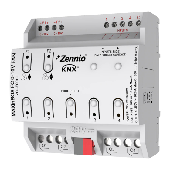
- Page 1 MAXinBOX FC 0-10V FAN 2x Two/Four-Pipe Fan Coil Controller with 0-10 VDC Fan Control Signal ZCL-FC010F Application Program Version: [1.5] User Manual Version: [1.5]_a www.zennio.com...
-
Page 2: Table Of Contents
MAXinBOX FC 0-10V FAN CONTENTS Contents ............................2 Document updates ........................4 1 Introduction ..........................5 1.1 MAXinBOX FC 0-10V FAN ....................5 1.2 Installation ........................7 1.3 Start-up and Power Loss ....................8 2 Configuration ........................... 9 2.1 General ..........................9 2.2 Inputs .......................... - Page 3 MAXinBOX FC 0-10V FAN Annex II: Operation Examples ..................... 36 Annex III: Communication objects ....................38 http://www.zennio.com Technical Support: http://support.zennio.com...
-
Page 4: Document Updates
MAXinBOX FC 0-10V FAN DOCUMENT UPDATES Version Changes Page(s) Changes in the application program: • Optimisation of modules: Heartbeat, Master Light, Binary Inputs, Individual Digital Outputs, Logic [1.5]_a Functions, Motion Detector, Thermostat Temperature Probe. • Support for long messages in ETS download. -
Page 5: Introduction
1 INTRODUCTION 1.1 MAXinBOX FC 0-10V FAN MAXinBOX FC 0-10V FAN from Zennio is a versatile KNX multi-function actuator that aims at fulfilling the climate control needs of KNX environments with integrated fan coil units where the fan speed is controlled through an analogue 0-10 VDC signal, while the gates of the water pipes need to be controlled through binary outputs (relays). - Page 6 Heartbeat or periodical “still-alive” notification. The MAXinBOX FC 0-10V FAN application program focuses on the control of fan coil drives that consist of two or four pipes (each with its own open/close valve) and a fan system whose speed is controlled through a 0 to 10 VDC analogue signal (more voltage means more speed).
-
Page 7: Installation
MAXinBOX FC 0-10V FAN 1.2 INSTALLATION MAXinBOX FC 0-10V FAN connects to the KNX bus through the on-board KNX connector. Once the device is provided with power from the KNX bus, both the individual address and the associated application program may be downloaded. -
Page 8: Start-Up And Power Loss
Please consult the next sections of this document for further details. On the other hand, when a bus power failure takes place, MAXinBOX FC 0-10V FAN will interrupt any pending actions, and will save its state so it can be recovered once the power supply is restored. -
Page 9: Configuration
MAXinBOX FC 0-10V FAN 2 CONFIGURATION After importing the corresponding database in ETS and adding the device into the topology of the desired project, the configuration process begins by entering the Parameters tab of the device. 2.1 GENERAL The first parameterisable screen available by default is “General”. From this screen it is possible to activate/deactivate all the required functionality. - Page 10 MAXinBOX FC 0-10V FAN power failure). It is possible to parameterise a certain delay for this sending (0 to 255 seconds). Figure 3. Sending of Indication objects on bus voltage recovery Heartbeat (Periodical Alive Notification): this parameter lets the integrator incorporate a one-bit object to the project (“[Heartbeat] Object to Send ‘1’”)
-
Page 11: Inputs
It is possible to connect motion detectors (models ZN1IO-DETEC-P and ZN1IO- DETEC-X from Zennio) to the input ports of MAXinBOX FC 0-10V FAN. This brings the device with the possibility of monitoring motion and presence in the room, as well as the light level. - Page 12 Motion detectors with references ZN1IO-DETEC and ZN1IO-DETEC-N are not compatible with MAXinBOX FC 0-10V FAN (may report inaccurate measurements if connected to this device). When connected to MAXinBOX FC 0-10V FAN, the rear micro-switch of model ZN1IO-DETEC-P should be set to position “Type B”. http://www.zennio.com Technical Support: http://support.zennio.com...
-
Page 13: Binary Outputs
MAXinBOX FC 0-10V FAN 2.3 BINARY OUTPUTS MAXinBOX FC 0-10V FAN incorporates four binary outputs, each of which can be enabled and configured in parameters independently. Although in this device they are offered with the aim of controlling the gate valves of the fan coil tubes (up to four), their parameterisation is similar to that of the individual relay outputs of any other MAXinBOX actuators. -
Page 14: 0-10V Analogue Outputs
MAXinBOX FC 0-10V FAN 2.4 0-10V ANALOGUE OUTPUTS MAXinBOX FC 0-10V FAN incorporates two analogue voltage outputs that provide a voltage signal in the range 0 to 10 VDC. This voltage will be in accordance to the percentage values that are received through a specific communication object. - Page 15 MAXinBOX FC 0-10V FAN After enabling any of them, two objects are included by default: “[AOx] Output Value (Control)”: this object is supposed to receive percentage values from the KNX bus, making the device generate a voltage output between 0 V and 10 V (proportional to the percentage value).
- Page 16 MAXinBOX FC 0-10V FAN Initialization: brings the option to set the output to a particular state at the start-up of the actuator. ➢ Default: off after an ETS download, and unchanged after a bus power failure. ➢ Custom: this option brings two new parameters: •...
-
Page 17: Fan Coils
MAXinBOX FC 0-10V FAN 2.5 FAN COILS MAXinBOX FC 0-10V FAN incorporates two independent fan coil functions that implement all the logic involved in the control of up to two fan coil units. ETS PARAMETERISATION After enabling “Fan Coils” in the General screen (see section 2.1), a new tab will be incorporated into the tree on the left. - Page 18 MAXinBOX FC 0-10V FAN is not able to effectively start motion with voltage values lower than a certain percentage. This is called “Offset 2” in Figure 9. % Output 100 % Open valve Offset 2 % Input 100 % Offset 1 Offset 2 Figure 9 Output percentage value depending on the input setpoint and the offsets.
- Page 19 MAXinBOX FC 0-10V FAN Type of Fan Coil: sets the type of the fan coil. The options are: “2 pipes” and “4 pipes”. Under “2 pipes”, it is necessary to set the operating Mode: Mode: sets the operating mode of the fan coil system. The options are: “Cooling”, “Heating”...
-
Page 20: Advanced Settings
MAXinBOX FC 0-10V FAN Minimum Fan Speed: from 0 to 100% (20% by default). This value must be higher or equal than the Minimum Control. Note: both offsets must be lower than the Maximum Fan Speed parameter (see 2.5.1.2). Depending on the mode, the following delays must be configured: Delay for Fan Activation when Valve Opens: time to wait since the valve opens until the fan can be turned on. - Page 21 MAXinBOX FC 0-10V FAN % Output 100 % Valve Open Max. Offset 2 % Input Offset 1 Offset 2 100 % Figure 11 Output percentage depending on the input setpoint, the two offsets and the maximum. % Output 100 % Valve open Max.
- Page 22 MAXinBOX FC 0-10V FAN Any control order is ignored, but taken into account after leaving this mode. The forced position resumes after a power failure. An Off order will be performed as usual, and leads to leaving the forced position mode.
- Page 23 MAXinBOX FC 0-10V FAN ETS PARAMETERISATION After enabling “Advanced Settings” in the Configuration screen of the fan coil function, a new tab will be incorporated into the tree on the left. Figure 13 Fan Coil X – Advanced Settings. The following parameters can be configured: Fan Coil Always On?: sets whether the fan coil will always be on or not.
- Page 24 MAXinBOX FC 0-10V FAN Enable Forced Position Object: when enabled, a new communication object (“[FCx] Forced Position”) becomes available. When it receives the value “1” and the system is on, the system enters the forced position mode, and the fan speed is set to the value set by the following parameter: ➢...
-
Page 25: Logic Functions
KNX bus, and to send the results through other communication objects specifically enabled for this purpose. MAXinBOX FC 0-10V FAN can implement up to 20 different and independent functions, each of them entirely customisable and consisting in up to 4 consecutive operations each one. -
Page 26: Thermostats
MAXinBOX FC 0-10V FAN 2.7 THERMOSTATS MAXinBOX FC 0-10V FAN implements two Zennio Thermostats which can be independently enabled and fully customised. Please refer to the “Zennio Thermostat” specific manual available under the MAXinBOX FC 0-10V FAN product section at the Zennio homepage, www.zennio.com... -
Page 27: Manual Control
MAXinBOX FC 0-10V FAN 2.8 MANUAL CONTROL MAXinBOX FC 0-10V FAN allows manually switching the state of its binary and 0-10V analogue outputs through the respective pushbuttons on the top of the device. A specific pushbutton is therefore available per output. - Page 28 MAXinBOX FC 0-10V FAN The action performed depends on the output type and, in the case of 0-10V analogue outputs, on the press type. For both outputs types, the presses have no effect if the output is disabled in parameters.
- Page 29 MAXinBOX FC 0-10V FAN Depending on the type of output, binary or analogue, the reactions to the button presses will differ. Binary output: short or long-pressing the button will commute the on-off state of the relay. 0-10V analogue output: the behaviour is the same as described for the Test Off Mode, except that the fan status objects do not change (they will be updated when leaving the Test On Mode).
- Page 30 MAXinBOX FC 0-10V FAN stated before, using the Test Off mode does not require any special action, while switching to the Test On mode does require long-pressing the Prog./Test button. Manual Control Lock: unless the above parameter has been “Disabled”, enabling the Lock Manual Control parameter will provide a runtime procedure for locking the manual control.
-
Page 31: Master Light
The Master Light function brings the option to monitor the state of up to 12 light sources (or even more, if the Master Light controls from multiple Zennio devices are linked together) or of any other elements whose state is transmitted through a binary object and, depending on those states, perform a master order every time a certain trigger signal (again, a binary value) is received through a specific object. - Page 32 MAXinBOX FC 0-10V FAN ETS PARAMETERISATION Once the Master Light function has been enabled, a specific tab will be included in the menu on the left. This new parameter screen () contains the following options: Number of State Objects: defines the number of 1-bit status objects required.
- Page 33 MAXinBOX FC 0-10V FAN (configurable in “Value”, being the options “Auto”, “Comfort”, “Standby”, “Economy” and “Building Protection”) whenever the general switch-off takes off Note: the above options are not mutually exclusive; it is possible to send values of different nature together.
-
Page 34: Annex I: Independence Of The Modules
MAXinBOX FC 0-10V FAN ANNEX I: INDEPENDENCE OF THE MODULES The following figures illustrate how the communication objects and group addresses of the fan coil and the outputs modules should be linked depending on the system to control. Two-Pipe Fan Coil System... - Page 35 MAXinBOX FC 0-10V FAN respective communication objects) or not. This makes the device more versatile and capable of controlling fan coils systems with their own valve / fan actuators by linking the objects of the fan coil module to the objects of the external actuators.
- Page 36 MAXinBOX FC 0-10V FAN ANNEX II: OPERATION EXAMPLES The device operation varies notoriously depending on the current state and the parameterisation. The following diagrams show the expected behaviour in different situations. On/Off Orders FC MODULE Off. Heating mode. heating %Control = 0...
- Page 37 MAXinBOX FC 0-10V FAN Mode orders Control Variable (heating) Heating Cooling V ≥ Offset1 FC MODULE Cooling mode. heating cooling heating activation deactivation deactivation Heating Cooling Speed = 0% (status) (status) Speed V>0% Valve Control = Valve Control = Open...
- Page 38 MAXinBOX FC 0-10V FAN ANNEX III: COMMUNICATION OBJECTS “Functional range” shows the values that, with independence of any other values permitted by the bus according to the object size, may be of any use or have a particular meaning because of the specifications or restrictions from both the KNX standard or the application program itself.
- Page 39 MAXinBOX FC 0-10V FAN 17, 47 1 Bit C - - W - DPT_Step [Tx] Setpoint Step 0 = -0.5ºC; 1 = +0.5ºC 18, 48 2 Bytes C - - W - DPT_Value_Tempd -670760.00° - 670760.00° [Tx] Setpoint Offset Float Offset Value...
- Page 40 MAXinBOX FC 0-10V FAN 89, 118, 147, 176 1 Bit C - - W - DPT_Window_Door [Ix] Presence Trigger Binary Value to Trigger the Presence Detection 90, 119, 148, 177 1 Bit C - - W - DPT_Ack [Ix] Presence: Slave Input 0 = Nothing;...
- Page 41 MAXinBOX FC 0-10V FAN 243, 249, 255, 261 1 Bit C - - W - DPT_Enable [Ix] Input Lock 0 = Unlock; 1 = Lock 1 Bit C T - - - DPT_Switch [Ix] [Short Press] 0 Sending of 0...
- Page 42 MAXinBOX FC 0-10V FAN 1 Byte C T - - - DPT_Value_1_Ucount 0 - 255 [Ix] [Short Press] Constant Value (Integer) 0 - 255 [Ix] [Short Press] Constant Value 1 Byte C T - - - DPT_Scaling 0% - 100%...
- Page 43 MAXinBOX FC 0-10V FAN 1 Bit C T - - - DPT_Switch [Ix] [Long Press] Light On Sending of 1 (On) 1 Bit C T - - - DPT_Switch [Ix] [Long Press] Light Off Sending of 0 (Off) 1 Bit...
- Page 44 MAXinBOX FC 0-10V FAN 349, 352 1 Byte C - - W U DPT_Scaling 0% - 100% [AOx] Output Value (Control) 0 - 100 % 350, 353 1 Byte C T R - - DPT_Scaling 0% - 100% [AOx] Output Value (Status)
- Page 45 MAXinBOX FC 0-10V FAN 3=Economy 4=Building Protection 1 Bit C T - - - DPT_Switch [ML] Courtesy Switch On: Binary Object Switch On Sending 1 Byte C T - - - DPT_Scaling 0% - 100% [ML] Courtesy Switch On: Scaling...
- Page 46 Join and send us your inquiries about Zennio devices: http://support.zennio.com Zennio Avance y Tecnología S.L. C/ Río Jarama, 132. Nave P-8.11 45007 Toledo (Spain). Tel. +34 925 232 002. www.zennio.com info@zennio.com...
Need help?
Do you have a question about the MAXinBOX FC 0-10V FAN and is the answer not in the manual?
Questions and answers