
Related Manuals for Zennio MAXinBOX 24 ZIO-MB24


Summary of Contents for Zennio MAXinBOX 24 ZIO-MB24
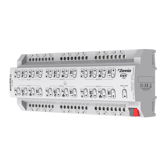
- Page 1 ➢ MAXinBOX 24 Multifunction Actuator with 24 Outputs ZIO-MB24 Application programme version: [1.1] User manual edition: [1.1]_a www.zennio.com...
-
Page 2: Table Of Contents
1.3 Start-Up and Power Loss ....................6 Configuration......................... 7 2.1 General ..........................7 2.2 Outputs..........................9 2.3 Manual Control ......................10 2.4 Logic Functions ....................... 14 2.5 Scene Temporisation ...................... 15 ANNEX I. Communication Objects....................17 http://www.zennio.com Technical Support: http://support.zennio.com... -
Page 3: Document Updates
MAXinBOX 24 DOCUMENT UPDATES Version Changes Page(s) Changes in the application program: [1.1_a] • Parameters reorganization. http://www.zennio.com Technical Support: http://support.zennio.com... -
Page 4: Introduction
MAXinBOX 24 1 INTRODUCTION 1.1 MAXinBOX 24 MAXinBOX 24 from Zennio is a versatile KNX actuator featuring a wide variety of functions: 24 relay outputs, configurable as: ➢ Up to 12 independent shutter channels (with or without slats), ➢ Up to 24 individual ON/OFF outputs, ➢... -
Page 5: Installation
To get detailed information about the technical features of this device, as well as on the installation and security procedures, please refer to the corresponding Datasheet, bundled with the original device packaging and also available at www.zennio.com. http://www.zennio.com Technical Support:... -
Page 6: Start-Up And Power Loss
For safety reasons, all shutter channels will be stopped (i.e., the relays will open) if a power loss takes place, while the individual outputs and fan coil contacts will switch to the specific state configured in ETS (if any). http://www.zennio.com Technical Support: http://support.zennio.com... -
Page 7: Configuration
Sending of Indication Objects (0 and 1) on Bus Voltage Recovery: this parameter lets the integrator activate two new communication objects (“Reset 0” and “Reset 1”), which will be sent to the KNX bus with values “0” and “1” http://www.zennio.com Technical Support: http://support.zennio.com... - Page 8 ("[Relay X] Number of Switches") and the maximum number of switches carried out in a minute ("[Relay X] Maximum Switches per Minute"). http://www.zennio.com Technical Support: http://support.zennio.com...
-
Page 9: Outputs
24 individual outputs. For detailed information about the functionality and the configuration of the related parameters, please refer to the following specific manuals, all of them available within the MAXinBOX 24 product section at the Zennio website (www.zennio.com): Individual outputs. Shutter channels. -
Page 10: Manual Control
Individual output: a simple press (short or long) will make the output switch its on-off state, which will be reported to the KNX bus through the http://www.zennio.com Technical Support: http://support.zennio.com... - Page 11 Regarding the lock, timer, alarm and scene functions, the device will behave under the Test Off mode as usual. Button presses during this mode are entirely analogous to the reception of the corresponding orders from the KNX bus. http://www.zennio.com Technical Support: http://support.zennio.com...
- Page 12 Test On mode. Status objects will not be sent to the bus, either. Important: the device is delivered from factory with all the outputs disabled, and with both manual modes (Test Off and Test On) enabled. http://www.zennio.com Technical Support: http://support.zennio.com...
- Page 13 “Last Value” (default; on the very first start-up, this will be Unlocked. The default values of each parameter will be highlighted in blue in this document, as follows: [default/rest of options]. http://www.zennio.com Technical Support: http://support.zennio.com...
-
Page 14: Logic Functions
Please refer to the “Logic Functions” user manual, available within the MAXinBOX 24 product section at the Zennio homepage, www.zennio.com, for detailed information about the functionality and the configuration of the related parameters. -
Page 15: Scene Temporisation
Enabling a certain scene number n brings a new tab with such name to the menu on the left, from which it is possible to configure the temporisation of that scene for each of the outputs where it has been configured. http://www.zennio.com Technical Support: http://support.zennio.com... - Page 16 Therefore, parameter “Scene m. Z Delay” [0…3600 [s] / 0…1440 [min] / 0…24 [h]] defines the delay that will be applied to the action defined in Z for the execution of scene m (where Z may be a specific individual output, shutter channel or fan coil module). http://www.zennio.com Technical Support: http://support.zennio.com...
-
Page 17: Annex I. Communication Objects
9, 20, 31, 42, 53, 64, 75, 86, 97, 108, 119, 130, 141, 152, 163, 174, 1 Bit C - - W - DPT_Start [Ox] Timer 0=Switch Off; 1=Switch On 185, 196, 207, 218, 229, 240, 251, 262 http://www.zennio.com Technical Support: http://support.zennio.com... - Page 18 C - - W - DPT_Enable [Cx] Lock 0=Unlock; 1=Lock 552, 580 273, 301, 329, 357, 385, 413, 441, 469,497, 525, 1 Byte C - - W - DPT_Scaling 0% - 100% [Cx] Shutter Positioning 0%=Top; 100%=Bottom 553, 581 http://www.zennio.com Technical Support: http://support.zennio.com...
- Page 19 287, 315, 343, 371, 399, 1 Bit C T - W U DPT_Scene_AB [Cx] Sunshine/Shadow 0=Sunshine; 1=Shadow 427, 455, 483, 511, 539, 1 Bit C T - W U DPT_Scene_AB [Cx] Sunshine/Shadow 0=Shadow; 1=Sunshine 567, 595 http://www.zennio.com Technical Support: http://support.zennio.com...
- Page 20 C T R - - DPT_Switch [FCx] Fan: Manual/Automatic (Status) 0 = Automatic; 1 = Manual 612, 644, 676, 708, 740, 1 Bit C T R - - DPT_Switch [FCx] Fan: Manual/Automatic (Status) 0 = Manual; 1 = Automatic http://www.zennio.com Technical Support: http://support.zennio.com...
- Page 21 DPT_Scaling 0% - 100% [FCx] Cooling Fan: Continuous Control 0 - 100% 626, 658, 690, 722, 754, 1 Byte C - - W U DPT_Scaling 0% - 100% [FCx] Cooling Valve: PI Control 0 - 100% http://www.zennio.com Technical Support: http://support.zennio.com...
- Page 22 854, 855, 856, 857, 858, 859, 860, 861, 862 863, 864, 865, 866, 867, 1 Byte C - - W - DPT_Value_1_Ucount 0 - 255 [LF] (1-Byte) Data Entry x 1-Byte Data Entry (0-255) 868, 869, 870, 871, 872, http://www.zennio.com Technical Support: http://support.zennio.com...
- Page 23 984, 986, 988, 990, 992, 994, 996, 998, 1000, [Relay x] Maximum Switches per 2 Bytes C T R - - DPT_Value_2_Ucount 0 - 65535 Maximum Switches per Minute 1002, 1004, 1006, 1008, Minute 1010, 1012, 1014, 1016, 1018, 1020 http://www.zennio.com Technical Support: http://support.zennio.com...
- Page 24 Join and send us your inquiries about Zennio devices: http://support.zennio.com Zennio Avance y Tecnología S.L. C/ Río Jarama, 132. Nave P-8.11 45007 Toledo (Spain). Tel. +34 925 232 002 www.zennio.com info@zennio.com...
Need help?
Do you have a question about the MAXinBOX 24 ZIO-MB24 and is the answer not in the manual?
Questions and answers