
Related Manuals for Zennio inBOX 24 v2


Summary of Contents for Zennio inBOX 24 v2
- Page 1 ➢ inBOX 24 v2 / inBOX 20 v2 Multifunction Actuator for Flush Mounting ZIOIB24V2 ZIOIB20V2 dsñkmfroi Application program version: [1.1], [1.2] User manual edition: [1.2]_a www.zennio.com...
-
Page 2: Table Of Contents
24 v2 / inBOX 20 v2 CONTENTS Contents ............................2 Introduction .......................... 3 1.1 inBOX 24 v2 / inBOX 20 v2 ....................3 1.2 Installation ........................4 1.3 Start-Up and Power Loss ....................5 Configuration......................... 6 2.1 General ..........................6 2.2 Inputs (Only inBOX 24 v2) .................... -
Page 3: Introduction
1 INTRODUCTION 1.1 inBOX 24 v2 / inBOX 20 v2 inBOX 24 v2 and inBOX 20 v2 from Zennio are two versatile KNX actuators featuring two relay outputs (together with four analogue-digital inputs, in the case of inBOX 24 v2) and a variety of functions. Their particularly small size makes them suitable for installation within mechanism boxes, junction boxes, roller shutter boxes or any other location where the available space is limited. -
Page 4: Installation
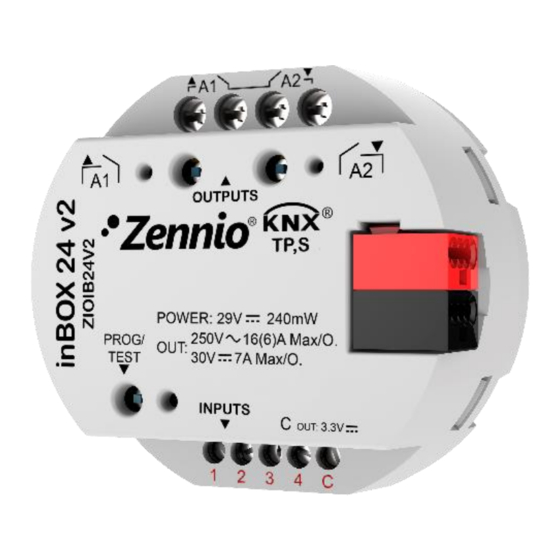
KNX connector. Figure 1. inBOX 24 v2. Elements Note: the above element diagram refers to inBOX 24 v2. It is entirely analogous for inBOX 20 v2, although the inputs are not available. The main elements of the device are described next. -
Page 5: Start-Up And Power Loss
To get detailed information about the technical features of this device, as well as on the installation and security procedures, please refer to the corresponding Datasheet, bundled with the original package of the device and also available at www.zennio.com. 1.3 START-UP AND POWER LOSS During the start-up of the device, the Test/Prog. -
Page 6: Configuration
Figure 2. Default screen Once activated, Inputs (only on inBOX 24 v2), Outputs, Logic Functions, Thermostats (only on inBOX 24 v2), Master Light (only on inBOX 24 v2), Scene Temporisation and Manual Control bring additional tabs to the menu on the left. These functions and their parameters will be explained in later sections of this document. - Page 7 24 v2 / inBOX 20 v2 Sending of Indication Objects (0 and 1) on Bus Voltage Recovery: this parameter lets the integrator activate two new communication objects (“Reset 0” and “Reset 1”), which will be sent to the KNX bus with values “0” and “1”...
-
Page 8: Inputs (Only Inbox 24 V2)
All inputs are disabled by default. Depending on the function selected for each input, additional tabs will be included in the menu on the left. 2.2.1 BINARY INPUT Please refer to the specific user manual “Binary Inputs”, available in the inBOX 24 v2 ¡product section, at the Zennio website (www.zennio.com). http://www.zennio.com Technical Support: http://support.zennio.com... -
Page 9: Temperature Probe
24 v2 product section, at the Zennio website (www.zennio.com). 2.2.3 MOTION DETECTOR It is possible to connect motion detectors from Zennio to the input ports of inBOX 24 Please refer to the specific user manual “Motion Detector”, available in the inBOX 24 v2 product section, at the Zennio website (www.zennio.com), for detailed information... -
Page 10: Outputs
For detailed information about the functionality and the configuration of the related parameters, please refer to the following specific manuals, all of them available in the inBOX 24 / 20 v2 product section at the Zennio homepage (www.zennio.com): Individual outputs. - Page 11 24 v2 / inBOX 20 v2 mode. After that, an additional press will turn the LED yellow and then off, once the button is released. This way, the device leaves the Test On mode. Note that it will also leave this mode if a bus power failure takes place.
- Page 12 24 v2 / inBOX 20 v2 Test On Mode After entering the Test On mode, it will only be possible to control the outputs through the on-board pushbuttons. Orders received through communication objects will be ignored, with independence of the channel or the output they are addressed to.
- Page 13 24 v2 / inBOX 20 v2 Figure 6. Manual control screen Manual Control: options are “Disabled”, “Only Test Mode Off”, “Only Test Mode On” and “Test Mode Off + Test On Mode” (default). Depending on the selection, the device will permit using the manual control under the Test Off, the Test On, or both modes.
-
Page 14: Logic Functions
Please refer to the specific “Logic Functions” user manual (available in the inBOX 24 / 20 v2 product section at the Zennio homepage, www.zennio.com) for detailed information about the functionality and the configuration of the related parameters. -
Page 15: Thermostats (Only Inbox 24 V2)
24 v2 / inBOX 20 v2 2.5 THERMOSTATS (ONLY inBOX 24 v2) inBOX 24 v2 implements four Zennio thermostats which can be enabled and configured independently. Please refer to the specific “Zennio Thermostat” user manual (available in the inBOX 24 v2 product section at the Zennio homepage, www.zennio.com) for detailed... -
Page 16: Master Light (Only Inbox 24 V2)
24 v2 / inBOX 20 v2 2.6 MASTER LIGHT (ONLY inBOX 24 v2) The Master Light function brings the option to monitor the state of up to 12 light sources –or any other functionally-similar element whose state is transmitted through a binary object–... - Page 17 24 v2 / inBOX 20 v2 Trigger Value: sets the value (“0”, “1” or “0/1”, being the latter the default option) that will trigger, when received through “[ML] Trigger”, the master action (the general switch-off or the courtesy switch-on).
- Page 18 24 v2 / inBOX 20 v2 (when the courtesy switch-on takes place), in contrast to object “[ML] General Switch-Off: Binary Object”, which sends the value “0” (during the general switch-off, as explained above). Figure 7. Sending of Indication objects on bus voltage recovery http://www.zennio.com...
-
Page 19: Scene Temporisation
24 v2 / inBOX 20 v2 2.7 SCENE TEMPORISATION The scene temporisation allows imposing delays over the scenes of the outputs. These delays are defined in parameters, and can be applied to the execution of one or more scenes that may have been configured. - Page 20 24 v2 / inBOX 20 v2 Figure 9. Configuration of the scene temporisation Therefore, parameter “Scene m. Z Delay” defines the delay that will be applied to the action defined in Z for the execution of scene m (where Z may be a specific individual output, shutter channel or fan coil module).
-
Page 21: Annex I. Communication Objects
“Functional range” shows the values that, with independence of any other values permitted by the bus according to the object size, may be of any use or have a particular meaning because of the specifications or restrictions from both the KNX standard or the application program itself. Note: objects referring to inputs, thermostats and the master light control only apply to inBOX 24 v2. Number... - Page 22 24 v2 / inBOX 20 v2 14, 52, 90, 128 1 Bit C - - W - DPT_Window_Door [Tx] Window Status (Input) 0 = Closed; 1 = Open 15, 53, 91, 129 1 Bit C - - W -...
- Page 23 24 v2 / inBOX 20 v2 1 Bit C T R - - DPT_Switch [Tx] [Sx] Control Variable (Heat) PI Control (PWM) 1 Bit C T R - - DPT_Switch [Tx] [Sx] Control Variable 2-Point Control 1 Bit C T R - -...
- Page 24 24 v2 / inBOX 20 v2 1 Bit C T - - - DPT_UpDown [Ix] [Short Press] Move Up Shutter Sending of 0 (Up) 1 Bit C T - - - DPT_UpDown [Ix] [Short Press] Move Down Shutter Sending of 1 (Down)
- Page 25 24 v2 / inBOX 20 v2 [Ix] [Short Press] Constant Value 1 Byte C T - - - DPT_Scaling 0% - 100% 0% - 100% (Percentage) [Ix] [Short Press] Constant Value 2 Bytes C T - - - DPT_Value_2_Ucount...
- Page 26 24 v2 / inBOX 20 v2 0x7 (Dec. by 1%) 0x8 (Stop) 0xD (Inc. by 100%) 0xF (Inc. by 1%) 1 Bit C T - - - DPT_Switch [Ix] [Long Press] Light On Sending of 1 (On) 1 Bit...
- Page 27 24 v2 / inBOX 20 v2 Detection 0 = Nothing; 1 = Detection from slave 249, 278, 307, 336 1 Bit C - - W - DPT_Ack [Ix] Presence: Slave Input device 250, 279, 308, 337 2 Bytes C - - W -...
- Page 28 24 v2 / inBOX 20 v2 (Save 1 - 64) 1 Bit C - - W - DPT_UpDown [CA] Move 0=Raise; 1=Lower 1 Bit C - - W - DPT_Step [CA] Stop/Step 0=Stop/StepUp; 1=Stop/StepDown 1 Bit C - - W -...
- Page 29 24 v2 / inBOX 20 v2 1 Bit C - - W - DPT_Ack [CA] Direct Positioning 1 (Save) 0=No Action; 1=Save Current Position 1 Bit C - - W - DPT_Ack [CA] Direct Positioning 2 (Save) 0=No Action; 1=Save Current Position...
- Page 30 Join and send us your inquiries about Zennio devices: http://support.zennio.com Zennio Avance y Tecnología S.L. C/ Río Jarama, 132. Nave P-8.11 45007 Toledo (Spain). Tel. +34 925 232 002. www.zennio.com info@zennio.com...
Need help?
Do you have a question about the inBOX 24 v2 and is the answer not in the manual?
Questions and answers