
Related Manuals for Azbil MagneW FLEX+


Summary of Contents for Azbil MagneW FLEX+
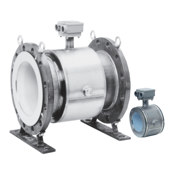
- Page 1 CM2-MGG200-2001 MagneW FLEX+/PLUS+ Electromagnetic Flowmeter Detector Model MGG11/18/MGG12/19/MGF11/MGS11U/28U User’s Manual...
- Page 2 In no event shall Azbil Corporation be liable to anyone for any indirect, special or consequential damages. This information and specifications in this document are subject to change without notice.
- Page 3 Safety About This Manual This manual contains information and warnings that must be observed to keep the model MGG/MGS Electromagnetic Flowmeter Detector operating safely. Correct installation, correct operation and regular maintenance are essential to ensure safety while using this device. In addition to this model MGG/MGS detector user manual, please refer to model MGG10C/14C converter user’s manual for start-up, calibration, trouble-shooting, operation, and maintenance of the complete Electromagnetic Flowmeter.
- Page 4 • Conductive adherents. For example, deposition of rosin or conductive material. • Insulating adherents. For example, oil, kaolinite, kaolin, or calcium stearate. CAUTION This model MGG/MGS detector can only be connected to Azbil Corporation's model MGG10C/14C converter. No other types of converters can be used with the device.
- Page 5 Azbil Corporation Safety CAUTION If the pipe is not filled, output errors will occur. CAUTION Do not rotate the unit more than 180° (one half rotation). Any further rotation can disconnect wiring. After removing the screws, do not pull on the terminal box. You can break the lead wire.
- Page 6 Safety Azbil Corporation CAUTION Tighten each bolt a little at a time and apply uniform pressure to all the bolts. If leakage continues after tightening the bolts, make sure that the pipe is not off center, then continue to tighten each bolt a little at a time.
-
Page 7: Table Of Contents
Table of Contents Chapter 1 : Introduction 1.1 : Principle of operation ..................1-1 1.2 : System operation ....................1-2 1.2.1: Integral type ......................1-2 1.2.2: Remote type ......................1-3 1.3 : Main components ....................1-4 1.3.1: Wafer type detector ..................... 1-5 1.3.2: Flange type detector ................... - Page 8 Table of Contents...
- Page 9 Table of Contents...
- Page 10 List of Figure Figure 1-1 Faraday’s law..................... 1-1 Figure 1-2 Integral configuration..................1-2 Figure 1-3 Remote Configuration..................1-3 Figure 1-4 Wafer detector main parts .................. 1-5 Figure 1-5 Flange detector main parts ................1-6 Figure 1-6 Union / Hose / Clamp detector main parts............1-7 Figure 1-7 Details of the clamp type detector ..............
- Page 11 List of Figure Figure 2-28 Installation on a PVC pipe using SUS grounding ring material and a protective plate ........................2-37 Figure 2-29 Installation on a PVC pipe using SUS grounding ring material with rubber gaskets (not recommended) ................2-38 Figure 2-30 Installation on a PVC pipe using Non-SUS grounding ring material and a specified torque....................
- Page 12 List of Figure...
- Page 13 List of Table Table 2-1 Fastening torque for wafer detectors ................2-7 Table 2-2 Recommended inner diameters of gaskets ..............2-10 Table 2-3 Inner and outer diameters of rubber gaskets of thickness 0.5 to 1 mm (0.02 to 0.04 inches) ... 2-11 Table 2-4 Inner and outer diameters of rubber gaskets of thickness 3 to 4 mm (0.12 to 0.16 inches) ..
- Page 14 List of Table...
-
Page 15: Chapter 1 : Introduction
Chapter 1 : Introduction 1.1 : Principle of operation The flowmeter consists of two parts: a detector which is mounted in the pipeline and through which the measured liquid flows, and a converter which may be mounted either integral with the detector or separately. The converter conditions and outputs the electrical signal from the detector or separately. -
Page 16: System Operation
Introduction Azbil Corporation 1.2 : System operation Introduction Depending on how it is combined with the converter, this product is available in two configurations, integral and remote. • Integral: Detector and converter are installed as an integrated unit on a pipe. -
Page 17: 2: Remote Type
Azbil Corporation Introduction 1.2.2: Remote type Converter AC power supply Dedicated cable Pulse output, Contact input/output Detector Analog output/ Digital output Excitation output Flow signal input Direction of fluid Figure 1-3 Remote Configuration MagneW Electromagnetic Flowmeter Detector FLEX+/PLUS+... -
Page 18: Main Components
Introduction Azbil Corporation 1.3 : Main components Detector There are three types of model MGG/MGS Electromagnetic Flowmeter Detectors: Wafer detectors, Flange detector, and Union / Hose / Clamp detector. The type of detector you choose depends on your specific installation requirements. All types of detectors function such that when a conductive fluid passes through the detectors, an electromotive force signal proportional to the flow rate is generated. -
Page 19: 1: Wafer Type Detector
Azbil Corporation Introduction 1.3.1: Wafer type detector A wafer detector consists of the components shown in the figure below. Grounding terminal Terminal box cover Waterproof gland Terminal box Flow direction mark Grounding ring Electrode cover Mounting screw (4 places) Figure 1-4 Wafer detector main parts... -
Page 20: 2: Flange Type Detector
Introduction Azbil Corporation 1.3.2: Flange type detector A Flange detector consists of the components shown in the figure below. Grounding terminal Terminal box cover Waterproof gland Terminal box Flow direction mark Flange Grounding ring Mounting screw Electrode cover (4 places) -
Page 21: 3: Union / Hose / Clamp Type Detector
Azbil Corporation Introduction 1.3.3: Union / Hose / Clamp type detector Grounding terminal Terminal box cover Waterproof gland Terminal box Mounting screw(4 places) Flow direction mark Union Clamp Electrode cover Hose Figure 1-6 Union / Hose / Clamp detector main parts... -
Page 22: 4: Sanitary Type Detector
Introduction Azbil Corporation 1.3.4: Sanitary type detector Figure 1-7 shows the structure of the detector and the names of its major parts. Grounding Terminal box terminal cover Waterproof gland Terminal Mounting screw (4 places) Electrode cover Ferrule Flow direction mark... -
Page 23: 5: Detector Terminal Box
Azbil Corporation Introduction 1.3.5: Detector terminal box The detector terminal box houses the connection terminals used for applying a standard voltage. Houses the excitation and signal terminals. WARNING ELECTRIC SHOCK HAZARD! Turn off power to the converter side before wiring. -
Page 24: 6: Approval Of This Device
Introduction Azbil Corporation 1.3.6: Approval of this device Overview If 1/2 NPT wiring connection is selected, this device functions as an FM/CSA, non- incendive -approved model. In this case, the installation standards described in this section must be followed. Installation of this device... - Page 25 Azbil Corporation Introduction If an MGG18/19 detector is used with an MGG14C converter as an FM-approved nonincendive product, both the detector and the converter should be FM-approved nonincendive products. If they are not, the MGG18/19 detector cannot be used as an FM-approved nonincendive product.
- Page 26 Introduction Azbil Corporation 1-12 MagneW Electromagnetic Flowmeter Detector FLEX+/PLUS+...
-
Page 27: Chapter 2 : Installation
Grounding ring material If you have questions regarding the specifications of your device, contact your nearest Azbil Corporation office or the azbil Group representative. When making an inquiry, be sure to provide the model number and product number of this device. -
Page 28: Storage
Installation Azbil Corporation 2.2 : Storage WARNING Before removing the unit, make sure that there is no residual liquid or pressure inside the piping and the detector to avoid personal injury or damage to the unit. When storing this device: •... -
Page 29: Site Selection
• Conductive adherents. For example, deposition of rosin or conductive material. • Insulating adherents. For example, oil, kaolinite, kaolin, or calcium stearate. CAUTION This model MGG/MGS detector can only be connected to Azbil Corporation's model MGG10C/14C converter. No other types of converter can be used with the device. -
Page 30: 1: Detector Position
Installation Azbil Corporation 2.3.1: Detector position • Position the detector so that its inner detector passage is continuously filled with the fluid being measured. The following figure provides examples. May not fill with fluid Air is easily trapped - may not fill with fluid... -
Page 31: 2: Changing The Position Of The Terminal Box
Azbil Corporation Installation Figure 2-3 Space allowance required for maintenance 2.3.2: Changing the position of the terminal box In some locations, the direction of the terminal box may be unsuitable if the detector is installed as it is shipped. In this case, the terminal box can be repositioned before installation. -
Page 32: Installing A Wafer Detector
Installation Azbil Corporation 2.4 : Installing a wafer detector CAUTION Before installing the detector, make sure any foreign matter is flushed from the interior passage of the detector. Residual foreign matter could cause output fluctuations. Do not touch the electrodes or allow oil or fat to come into contact with them to avoid output fluctuations. -
Page 33: 1: Determining The Fastening Torque
Azbil Corporation Installation 2.4.1: Determining the fastening torque The following table shows the fastening torque for each pipe bore. CAUTION The correct fastening torque must be used to prevent leakage. To avoid damage to the detector, do not exceed the listed fastening torque. -
Page 34: Figure 2-7 Unacceptable Positioning
Installation Azbil Corporation Tilted pipe Off-center Off-center Figure 2-7 Unacceptable positioning CAUTION Never attempt to force the detector between two flanges if the space is too narrow. It can damage the detector. Figure 2-8 Unacceptable placement of detector between flanges... -
Page 35: 3: Necessary Parts
Azbil Corporation Installation 2.4.3: Necessary parts You will need the following parts to install a wafer detector: • Centering nuts (four supplied) • Connecting bolts and nuts (available separately) • Gaskets: Required when using grounding rings made of SUS material. Not required when using grounding rings made of hastelloy, titanium, tantalum, or platinum. -
Page 36: Table 2-2 Recommended Inner Diameters Of Gaskets
Gaskets Gaskets are supplied with the grounding ring, except when it is made of SUS material. If you are using SUS material, you must provide the gaskets. Azbil Corporation recommends joint sheet or polytetraflouroethylene (PTFE) gasket material. For the inner (bore) diameters of the gaskets, see the following table. -
Page 37: Table 2-3 Inner And Outer Diameters Of Rubber Gaskets Of Thickness 0.5 To 1 Mm (0.02 To 0.04 Inches)
Azbil Corporation Installation Table 2-3 Inner and outer diameters of rubber gaskets of thickness 0.5 to 1 mm (0.02 to 0.04 inches) Nominal 2.5 5 100 125 150 200 detector (inch) 0.1 0.2 3/8 1/2 1 1½ 2 2½ 3... -
Page 38: 4: Selecting An Installation Method
Installation Azbil Corporation 2.4.4: Selecting an installation method To select an installation method you must determine the following: • Horizontal or vertical placement of the detector • Mounting pipe material • Grounding ring material • Need for a protective plate •... -
Page 39: 5: Installation On A Horizontal Pipe
Azbil Corporation Installation 2.4.5: Installation on a horizontal pipe To install a wafer detector on a horizontal pipe: Follow this procedure to install the detector on a horizontal pipe. Step Action Drawing • Insert through-bolts in the flange holes Flange shown by black dots in the drawing. -
Page 40: 6: Installation On A Vertical Pipe
Installation Azbil Corporation 2.4.6: Installation on a vertical pipe Follow this procedure to install the detector on a horizontal pipe. Step Action Drawing • Of the flange holes shown by black dots in the Flange Terminal drawing, insert through-bolts into the two holes box side at the back and fasten them lightly with nuts. -
Page 41: 7: Installation On A Metal Pipe Using Sus Grounding Ring Material
SUS grounding ring material. For the installation method corresponding to any other combination of materials, refer to Table 2-5 on page 2-12. For installation using SUS grounding ring material, Azbil Corporation recommends non-rubber gaskets such as joint sheet or PTFE. Although rubber gaskets can be used, it is not possible to reduce the fastening torque. -
Page 42: 8: Installation On A Metal Pipe Using Non-Sus Grounding Ring Material
Installation Azbil Corporation 2.4.8: Installation on a metal pipe using non-SUS grounding ring material The installation methods described in this section are for installation on a metal pipe using non-SUS grounding ring material. For the installation method corresponding to any other combination of materials, refer to Table 2-5 on page 2-12. -
Page 43: Figure 2-13 Installation On A Metal Pipe Using Non-Sus Grounding Ring Material With Rubber Gaskets
Azbil Corporation Installation To install a wafer detector on a metal pipe using non-SUS grounding ring material with rubber gaskets: CAUTION The use of anything other than the PTFE gaskets provided can result in leakage. The use of rubber gaskets is not recommended and can cause leakage. -
Page 44: Figure 2-14 Incorrect Installation
Installation Azbil Corporation Gasket PTFE gasket Lining Grounding ring Figure 2-14 Incorrect installation 2-18 MagneW Electromagnetic Flowmeter Detector FLEX+/PLUS+... -
Page 45: 9: Installation On A Pvc Pipe Using Sus Grounding Ring Material
Table 2-5 on page 2-12. PTFE gaskets are provided for this type of installation. If you supply the gaskets, Azbil Corporation recommends non-rubber gaskets such as joint sheet or PTFE. Although rubber gaskets can be used, they are not recommended. See page 2-21 for installation using rubber gaskets. -
Page 46: Figure 2-16 Installation On A Pvc Pipe Using Sus Grounding Ring Material And A Protective Plate
Installation Azbil Corporation To install a wafer detector on a PVC pipe using SUS grounding ring material and a protective plate: Use this method to install the detector using a protective plate to prevent the PVC pipe from being deformed or damaged when the bolts are tightened with the specified torque. -
Page 47: Figure 2-17 Installation On A Pvc Pipe Using Sus Grounding Ring Material With Rubber Gaskets (Not Recommended)
Azbil Corporation Installation To install a wafer detector on a PVC pipe using SUS grounding ring material with rubber gaskets and a low fastening torque: CAUTION The use of rubber gaskets and a lower fastening torque is not recommended and can cause insufficient surface pressure between the lining and the grounding ring, resulting in leakage. -
Page 48: 10: Installation On A Pvc Pipe Using Non-Sus Grounding Ring Material
Table 2-5 on page 2-12. PTFE gaskets are provided for this type of installation. If you supply the gaskets, Azbil Corporation recommends non-rubber gaskets such as joint sheet or PTFE. Although rubber gaskets can be used, they are not recommended. See page 2-24 for installation using rubber gaskets. -
Page 49: Figure 2-19 Installation On A Pvc Pipe Using Non-Sus Grounding Ring Material And A Protective Plate
Azbil Corporation Installation To install a wafer detector on a PVC pipe using non-SUS grounding ring material and a protective plate: Use this method to install the detector using a protective plate to prevent the PVC pipe from being deformed or damaged when the bolts are tightened with the specified torque. -
Page 50: Figure 2-20 Installation On A Pvc Pipe Using Non-Sus Grounding Ring Material With Rubber Gaskets
Installation Azbil Corporation To install a wafer detector on a PVC pipe using non-SUS grounding ring material with rubber gaskets and a low fastening torque: CAUTION The use of rubber gaskets and a lower fastening torque is not recommended and can cause insufficient surface pressure between the lining and the grounding ring, resulting in leakage. -
Page 51: Installing A Flanged Detector
Azbil Corporation Installation 2.5 : Installing a flanged detector CAUTION Before installing the detector, make sure any foreign matter is flushed from the interior passage of the detector. Residual foreign matter could cause output fluctuations. Do not touch the electrodes or allow oil or fat to come into contact with them to avoid output fluctuations. -
Page 52: 1: Determining The Fastening Torque
Installation Azbil Corporation 2.5.1: Determining the fastening torque The following table shows the fastening torque for each pipe bore. CAUTION The correct fastening torque must be used to prevent leakage. To avoid damage to the detector, do not exceed the listed fastening torque. -
Page 53: Table 2-9 Fastening Torque
Azbil Corporation Installation Table 2-6 Fastening torque for flanged detectors Nominal Fastening torque detector bore Flange ratings diameter N•m (ft•lb) mm (inch) kgf•cm 50 / 65 mm JIS 10K 24 - 34 (17.7 - 25.1) 245 - 347 (2 / 2½ inches) - Page 54 Installation Azbil Corporation Table 2-6 Fastening torque for flanged detectors Nominal Fastening torque detector bore Flange ratings diameter N•m (ft•lb) mm (inch) kgf•cm 200 mm JIS 10K 44 - 65 (32.5 - 47.9) 449 - 663 (8 inches) JIS 20K 66 - 102 (48.7 - 75.2)
- Page 55 Azbil Corporation Installation Table 2-6 Fastening torque for flanged detectors Nominal Fastening torque detector bore Flange ratings diameter N•m (ft•lb) mm (inch) kgf•cm 400 mm JIS 10K 72 - 88 (53.1 - 64.9) 734 - 897 (16 inches) JIS 20K 160 - 189 (118.0 - 139.4)
-
Page 56: Figure 2-22 Flange Shapes
Installation Azbil Corporation Flange shape selection The flanges used for installation should maximize the area of contact with the gasket. O Acceptable X Unacceptable Flange Welding Welding (The liquid could leak because of the small area of contact with the gasket.) -
Page 57: 2: Necessary Parts
Gaskets Gaskets are supplied with the grounding ring, except when it is made of SUS material. If you are using SUS material, you must provide the gaskets. Azbil Corporation recommends joint sheet or polytetraflouroethylene (PTFE) gasket material. For the inner diameters of the gaskets, see the following table. Rubber gaskets are not recommended. -
Page 58: 3: Selecting An Installation Method
Installation Azbil Corporation Table 2-7 Recommended inner diameters of gaskets Bore diameter mm (inch) Inner diameter mm (inch) 1100 (44) 1101±2 (43.35±0.08) 2.5.3: Selecting an installation method To select an installation method you must determine the following: • Mounting pipe material (metal or PVC) •... -
Page 59: 4: Installation On A Metal Pipe Using Sus Grounding Ring Material
SUS grounding ring material. For the installation method corresponding to any other combination of materials, refer to Table 2-8 on page 2-32. For installation using SUS grounding ring material, Azbil Corporation recommends non-rubber gaskets such as joint sheet or PTFE. See Table 2-7 on page 2-31 for recommended inner (bore) diameters. -
Page 60: 5: Installation On A Metal Pipe Using Non-Sus Grounding Ring Material
Table 2-8 on page 2-32. PTFE gaskets are provided for this type of installation. If you supply the gaskets, Azbil Corporation recommends non-rubber gaskets such as joint sheet or PTFE. To install a flanged detector on a metal pipe using non-SUS grounding ring material and a specified torque: •... -
Page 61: 6: Installation On A Pvc Pipe Using Sus Grounding Ring Material
Table 2-8 on page 2-32. PTFE gaskets are provided for this type of installation. If you supply the gaskets, Azbil Corporation recommends non-rubber gaskets such as joint sheet or PTFE. Although rubber gaskets can be used, they are not recommended. See page 2-38 for installation using rubber gaskets. -
Page 62: Figure 2-27 Installation On A Pvc Pipe Using Sus Grounding Ring Material And A Specified Torque
Installation Azbil Corporation To install a flanged detector on a PVC pipe using SUS grounding ring material with a specified fastening torque: • Install the detector as shown in the following illustration. The torque level for tightening the bolts is not related to the gasket material. -
Page 63: Figure 2-28 Installation On A Pvc Pipe Using Sus Grounding Ring Material And A Protective Plate
Azbil Corporation Installation To install a flanged detector on a PVC pipe using SUS grounding ring material and a protective plate: Use this method to install the detector using a protective plate to prevent the PVC pipe from being deformed or damaged when the bolts are tightened with the specified torque. -
Page 64: Figure 2-29 Installation On A Pvc Pipe Using Sus Grounding Ring Material With Rubber Gaskets (Not Recommended)
Installation Azbil Corporation To install a flanged detector on a PVC pipe using SUS grounding ring material with rubber gaskets and a low fastening torque: CAUTION The use of rubber gaskets and a lower fastening torque is not recommended and can cause insufficient surface pressure between the lining and the grounding ring, resulting in leakage. -
Page 65: 7: Installation On A Pvc Pipe Using Non-Sus Grounding Ring Material
Table 2-5 on page 2-12. PTFE gaskets are provided for this type of installation. If you supply the gaskets, Azbil Corporation recommends non-rubber gaskets such as joint sheet or PTFE. When using rubber gaskets, gaskets of the same material with two different thicknesses (0.5 to 1.0 mm (0.02 to 0.04 inch) and 3.0 to 4.0 mm (0.12 to 0.16... -
Page 66: Figure 2-30 Installation On A Pvc Pipe Using Non-Sus Grounding Ring Material And A Specified Torque
Installation Azbil Corporation To install a flanged detector on a PVC pipe using non-SUS grounding ring material with a specified fastening torque: • Install the detector as shown in the following illustration. The torque level for tightening the bolts is not related to the gasket material. -
Page 67: Figure 2-31 Installation On A Pvc Pipe Using Non-Sus Grounding Ring Material And A Protective Plate
Azbil Corporation Installation To install a flanged detector on a PVC pipe using non-SUS grounding ring material and a protective plate: Use this method to install the detector using a protective plate to prevent the PVC pipe from being deformed or damaged when the bolts are tightened with the specified torque. -
Page 68: Figure 2-32 Installation On A Pvc Pipe Using Non-Sus Grounding Ring Material With Rubber Gaskets
Installation Azbil Corporation To install a flanged detector on a PVC pipe using non-SUS grounding ring material with rubber gaskets and a low fastening torque: (1) Remove the grounding ring from the detector and insert a rubber gasket 0.5 to 1.0 mm (0.02 to 0.04 inch) thick. -
Page 69: Installing A Union / Hose / Clamp Detector
Azbil Corporation Installation 2.6 : Installing a Union / Hose / Clamp Detector 2.6.1: Installation of Union and Hose assemblies basic installation method Direction of installation Match the flow direction of the fluid to be measured to that of the flow direction mark on the electromagnetic flowmeter. -
Page 70: 2: Installation Of Iso-Clamp/ Tri-Clamp Assembles Basic Installation Method
Installation Azbil Corporation Figure 2-33 Example of installation (union assembly) 2.6.2: Installation of ISO-clamp/ Tri-clamp assembles basic installation method Example of clamp assembly Gasket Clamp Ferrule Welding Pipe Figure 2-34 Example of installation Welding a ferrule to the pipe Weld the supplied ferrule onto the pipe. In the welding process, pay special attention to the taper processing, butting stages, welding current, etc. - Page 71 Azbil Corporation Installation Mounting of the special gasket Mount the supplied special clamp gasket so that it fits into the groove of the gasket. WARNING Mount it carefully into the groove so that there is no misalignment of the gasket.
-
Page 72: Wiring The Detector
Installation Azbil Corporation 2.7 : Wiring the detector 2.7.1: Connecting the detector and converter (Remote models) The use of a dedicated cable (model MGA12W) is recommended for the connection between the detector and the converter. For detailed wiring information (including the dedicated cable) see the manual for the converter that you are using. -
Page 73: 2: Grounding The Detector (Remote Models)
Azbil Corporation Installation 2.7.2: Grounding the detector (Remote models) The detector is grounded via the external grounding terminal. CAUTION Insufficient grounding can cause output fluctuations, instability of the zero point, or output drift. Secure single point grounding with a grounding resistance of 100 W or less is recommended. -
Page 74: Figure 2-38 Dedicated Cable Structure
Installation Azbil Corporation Dedicated cable structure The structure of the dedicated cable is shown in the following figure. The cable must be properly dressed to insure proper connection. Inside shield Outside shield Conductive tube (black) Inside sheath Outside sheath (black) -
Page 75: Figure 2-40 Attaching The C-Wire
Azbil Corporation Installation Outside sheath Lead wire C-wire Attach the lead wire to the middle of this 5 mm Outside 5 mm (0.2 inch) length. 5 mm (0.2 inch) shield (0.2 inch) Figure 2-40 Attaching the C-wire CAUTION Be sure to use adequate solder so that contact failure will not occur between the C-wire and the outside shield. -
Page 76: Figure 2-42 Trimming The Inside Sheath
Installation Azbil Corporation Inside Black Inside shield C-wire C-wire sheath White 15 mm 15 mm (0.59 inch) (0.59 inch) Figure 2-42 Trimming the inside sheath (6) Wind each lead wire (SA and SB) around the inside shield once. (7) Solder the lead wired (SA and SB) to the middle of this 5 mm (0.2 inch) length. -
Page 77: Figure 2-44 Trimming The Inside Shield
Azbil Corporation Installation Conductive tube C-wire C-wire SA-wire SA-wire A-wire A-wire B-wire B-wire SB-wire SB-wire 5 mm (0.2 inch) 5 mm (0.2 inch) Conductive tube Figure 2-44 Trimming the inside shield (9) Peel off the conductive tube (black) completely up to the inside shield. -
Page 78: Figure 2-47 Terminal Connections
Installation Azbil Corporation Testing continuity Test the continuity between the following terminals of the trimmed cables. Table 2-10 Cable continuity Terminals Resistance A - A B - B C - C Testing the insulation Test the insulation between the following terminals using an insulation resistance tester. -
Page 79: Figure 2-48 Trimming The Outside Sheath
Azbil Corporation Installation Dressing the dedicated cable : Detector side To dress the dedicated cable: (1) Scribe (cut) a line in the outside sheath (black) as shown in the following figure and remove the sheathing. The length is 75mm (2.95 inch). -
Page 80: Figure 2-50 Trimming The Outside Shield
Installation Azbil Corporation (4) Cut the outside shield off at a point 5 mm (0.2 inch) from the outside sheath, leaving the specified length from the end of the outside shield. CAUTION Do not cut into the inside sheath. Outside sheath... -
Page 81: Figure 2-53 Attaching The Lead Wires (Sa And Sb)
Azbil Corporation Installation CAUTION Be sure to use adequate solder so that contact failure will not occur between the C -wire and the outside shield. If the soldering connection is insecure, noise is generated due to contact resistance. CAUTION Do not cut into the conductive tube. -
Page 82: Troubleshooting And Maintenance
Installation Azbil Corporation Testing continuity Test the continuity between the following terminals of the trimmed cables. Table 2-12 Cable continuity Terminals Resistance A - A B - B C - C Testing the insulation Test the insulation between the following terminals using an insulation resistance tester. - Page 84 Warranty period and warranty scope 1.1 Warranty period Azbil Corporation’s products shall be warranted for one (1) year from the date of your purchase of the said products or the delivery of the said products to a place designated by you.
- Page 85 Although acceleration of the above situation varies depending on the conditions or environment of use of the products, you are required not to use any Azbil Corporation’s products for a period exceeding ten (10) years unless otherwise stated in specifications or instruction manuals.
- Page 87 Document Number: CM2-MGG200-2001 Document Name: MagneW FLEX+/PLUS+ Electromagnetic Flowmeter Detector Model MGG11/18/MGG12/19/MGF11MGS11U/28U User’s Manual Date: 1st edition: Dec. 1997 7th edition: Feb. 2019 Issued/Edited by: Azbil Corporation...
Need help?
Do you have a question about the MagneW FLEX+ and is the answer not in the manual?
Questions and answers