Advertisement
Quick Links
No. CP-SP-1320E
Battery-Powered
MCF
Air Flowmeter
User's Manual
for
Installation and Configuration
Thank you for purchasing the MCF.
This manual contains information for
ensuring the correct use of the MCF. It
also provides necessary information for
installation, maintenance, and trou-
bleshooting.
This manual should be read by those
who design and maintain equipment
that uses the MCF. Be sure to keep this
manual nearby for handy reference.
Advertisement

Related Manuals for Azbil MCF Series


Summary of Contents for Azbil MCF Series
- Page 1 No. CP-SP-1320E Battery-Powered Air Flowmeter User's Manual Installation and Configuration Thank you for purchasing the MCF. This manual contains information for ensuring the correct use of the MCF. It also provides necessary information for installation, maintenance, and trou- bleshooting. This manual should be read by those who design and maintain equipment that uses the MCF.
- Page 2 If you should find an error or omis- sion, please contact Azbil Corporation. In no event is Azbil Corporation liable to anyone for any indirect, special or consequential damages as a result of using this product.
- Page 3 Conventions Used in This Manual I To prevent injury to the operator and others, and to prevent property damage, the following types of safety precautions are indicated: Warnings are indicated when mishandling this product might result in WARNING death or serious injury. Cautions are indicated when mishandling this product might result in CAUTION minor injury to the user, or only physical damage to the product.
- Page 4 If damage could result from the abnormal functioning of this device, include appropriate redun- dancy in the system design. If there is a risk of a power surge caused by lightning, use Azbil Corporation's SurgeNon to prevent possible fire or equipment failure.
- Page 5 CAUTION Battery life varies depending on the operating environment and the battery type. Do not remove the mounting bracket from the battery box. Mount so that the battery box cover is NOT facing down.
- Page 6 The Role of This Manual Three manuals are available for the MCF. Read appropriate manuals according to your requirements. If you do not have a required manual, contact the azbil Group or your dealer. Additionally, you can download necessary manuals from http://www.azbil.com.
- Page 7 Contents Conventions Used in This Manual Safety Precautions The Role of This Manual Chapter 1. OVERVIEW I Summary • • • • • • • • • • • • • • • • • • • • • • • • • • • • • • • • • • • • • • • • • • • • • • • • • • • • • • • • • • • • • • • • • I Features •...
- Page 8 Chapter 5. SETTING AND OPERATION I State transitions • • • • • • • • • • • • • • • • • • • • • • • • • • • • • • • • • • • • • • • • • • • • • • • • • • • • • • • • I Function setup •...
- Page 9 Chapter 1. OVERVIEW I Summary The MCF air flowmeter uses a µF (Micro Flow) sensor in its sensing unit. The µF sensor is a thermal flow speed sensor which uses proprietary technology. Integrating this ultra-miniature flow speed sensor with high-grade channel design technology has achieved high accuracy and wide rangeability.
- Page 10 Chapter 1. OVERVIEW I Model selection guide Basic Pipe size Material Connected Gas type Power/ Option Option Option Design Description model Flow rate output/ code range comm. MCF Air flowmeter 0080 8A (1/4B), 200L/min, full scale 0150 15A (1/2B), 500L/min, full scale 0151 15A (1/2B), 1000L/min, full scale 0250...
- Page 11 Chapter 1. OVERVIEW I Optional parts (sold separately) Name Model number Cable Cable Lead color length properties Cable with connector PA5-4ISX2SK Oil resistant, bend-tolerant 1: Brown exclusive for MCF PA5-4ISX3SK Flame-resistant cable 2: White series PA5-4ISX5SK UL2464 3: Blue EN-compliant 4: Black PA5-4ISX2HK-E Oil resistant...
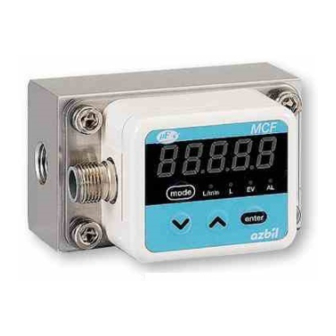
- Page 12 Chapter 2. PART NAMES AND FUNCTIONS I Parts name and functions Flow rate display Bolts mode L/min enter Display unit Connector Measurement module Inlet Outlet Main flow path Flow rate display: This 7-segment LED indicates instantaneous flow rate or inte- grated flow amount.
- Page 13 If damage could result from the abnormal functioning of this device, include appropriate redundancy in the system design. If there is a risk of a power surge caused by lightning, use Azbil Corporation's SurgeNon to prevent possible fire or equipment failure.
- Page 14 Chapter 3. MOUNTING AND WIRING I Piping G MCF_ _ _ _ _R pipe installation cautions • The MCF is a precision instrument. Do not drop it nor subject it to shock. • Install so that the direction of gas flow matches the arrow on the side of the MCF.
- Page 15 Chapter 3. MOUNTING AND WIRING G MCF _ _ _ _ _ G pipe installation cautions • The MCF is a precision instrument. Do not drop it nor subject it to shock. • Install so that the direction of gas flow matches the arrow on the side of the MCF.
- Page 16 Chapter 3. MOUNTING AND WIRING G Mounting direction Normally the MCF is mounted on a horizontal pipe with the display unit facing upward. Though the mounting position is unrestricted, measurement error might be caused by the display direction. Normal position on horizontal pipe with display facing upward (Position 1) Flow direction Side view Horizontal pipe with display rotated to the right as seen from air inlet (Position 2)
- Page 17 Chapter 3. MOUNTING AND WIRING • Horizontal pipe with the display facing right as seen from the air inlet (Position 2) Operating pressure range Flow rate range Instantaneous flow rate deviation ± 0 to 1 MPa 5 to 100 % of full scale flow rate 0.5 % FS per 0.1MPa 1 digit or less ±...
- Page 18 If a device that is not listed in the table is installed either upstream or downstream, contact the azbil Group for the length of the straight pipe section. If reverse flow is also expected, it is necessary to have the same length of straight pipe downstream as upstream.
- Page 19 Chapter 3. MOUNTING AND WIRING *3: MCF models and connecting pipe sizes are shown below. Model No./Pipe size 1/8 inch 1/4 inch 3/8 inch 1/2 inch 3/4 inch MCF0080 MCF0150/0151 Model No./Pipe size 3/4 inch 1 inch 1 1/4 inch 1 1/2 inch 2 inch 2 1/2 inch MCF0250...
- Page 20 Chapter 3. MOUNTING AND WIRING *6: The figures below show examples of connection with a single elbow and double elbow. *7: This valve does not have an internal throttle. If possible, install a flow regulating valve downstream from the MCF. *8: A regulator should be 200D away from this device.
- Page 21 Chapter 3. MOUNTING AND WIRING Pipe or connected device Location in Straight pipe section for this device relation to For accuracy within For accuracy the MCF specifications (±3 % FS) within ±5 % FS Tube fitting for air supply piping Upstream Tube dia.: 8 mm (internal dia.: 6 mm) Downstream...
- Page 22 Chapter 3. MOUNTING AND WIRING I Battery box and terminal locations G Mounting the battery box Mount the battery box securely on the pipe using U bolts, or on a wall using screws (U-bolt nut tightening torque: 0.7 -1.0 N •...
- Page 23 Chapter 3. MOUNTING AND WIRING G Mounting the alkaline batteries • Remove the battery box cover and set 4 AA alkaline batteries in the holder. Then attach the cover and tighten the screws * If the MCF display does not turn on, try reinserting the batteries. * Tightening torque: 1.3 -1.6 N·m.
- Page 24 Chapter 3. MOUNTING AND WIRING G Battery box output (connector B) Pin number Signal None None Alarm event Event output Wire color and pin number for MCF connector cable Pin number Signal Line color None Brown White Blue Black G Wiring example Load: 30 Vdc, 50 mA max.
- Page 25 Chapter 4. FUNCTIONS I Display Pressing any key when the display is off will turn it on again. After it turns on, if the amount of time specified in C05 has passed with no key operation, the display turns off automatically. G Instantaneous flow rate display and integrated flow display The user can display either instantaneous flow rate or integrated flow total on the 7- segment display.
- Page 26 Chapter 4. FUNCTIONS I Integration function Either integration count-up or integration count-down can be selected in the func- tion setup. • If the integrated value exceeds 999999990, it reverts to 0 and counting contin- ues. • In the integrated countdown function, the integrated value decreases from a pre- set value to 0.
- Page 27 Chapter 4. FUNCTIONS *: Pulse-weight Model Setup [L/pulse] Setup [m /pulse, kg/pulse] Minimum 10 times the 100 times the Minimum 10 times the 100 times the unit minimum unit minimum unit unit minimum unit minimum unit MCF0080 1000 0.01 MCF0150 1000 0.01 MCF0151...
- Page 28 Chapter 4. FUNCTIONS I Data storage Stored in a nonvolatile memory. Recording data: Functions setting, parameter setting, integrated value*, instanta- neous flow rate peak value* * Integrated value and instantaneous flow rate value are recorded at every 10 minutes. I Standby mode To reduce power consumption, the MCF automatically switches between two mea- surement cycles, 1 s (normal mode) and 10 s (standby mode).
- Page 29 Chapter 5. SETTING AND OPERATION ■ State transitions [mode] key 2 s or more Maintenance mode [mode] Power ON 2 s or more [mode] key [mode] key 2 s or more 2 s or more Function setup Parameter setup mode mode Instantaneous flow [mode] key...
- Page 30 Chapter 5. SETTING AND OPERATION ■ Function setup ● Setup method (1) Push and hold the [mode] key for 2 seconds or more in the normal indication mode. >> The function number is displayed in the first 3 digits and the current setting is displayed in the last 2 digits.
- Page 31 Chapter 5. SETTING AND OPERATION Func Name Settings Factory Description setting C0 1 Key lock setting 00: Unlocked Even with the keys locked, it is possible to 01: Key locked cancel the key lock. If any key is pressed while the keys are locked, “LOc.”...
- Page 32 Chapter 5. SETTING AND OPERATION Func Name Settings Factory Description setting C06 Alarm event 00: Alarm event (general) An alarm event can be output from terminal 01: AL59 battery alarm AL. If 00 is selected, the output is the same as 02: AL40 over range when 14 is selected in .
- Page 33 Chapter 5. SETTING AND OPERATION ■ Parameter setup ● Setup method (1) Push and hold the [mode] key 2 seconds or more in the normal indication mode. The device enters function setup mode. Again press and hold the [mode] key 2 seconds or more.
- Page 34 Chapter 5. SETTING AND OPERATION ● Parameter settings Item Name Setting range Factory Description setting E 1.SP Event 1 instantaneous flow rate 0 to 400 % FS • Setup is enabled when function setup C03 is equiv. set to 0 1 to 06. •...
- Page 35 Chapter 5. SETTING AND OPERATION (2) When C03 is set to 02 or 05 (instantaneous flow rate lower limit) If the flow rate falls below the instantaneous flow rate lower limit, event out- put turns on. The point at which event output turns off involves a hysteresis and is calculated as follows: Event OFF point = instantaneous flow rate lower limit + hysteresis Specify the hysteresis as a percentage of the full scale flow rate (% FS).
- Page 36 Chapter 5. SETTING AND OPERATION *4: Setting range The setting range depends on the model number and the flow rate indication units. See the table below. C02setting MCF0080 MCF0150 MCF0151 MCF0250 MCF0400 MCF0500 Notes The upper limit 00: [L/min] 0 to 480 0 to 1200 0 to 2400 0 to 7200...
-
Page 37: Table Of Contents
Chapter 5. SETTING AND OPERATION ■ Device information display ● Viewing the display (1) Press and hold the [enter] key for 2 seconds or more while the instantaneous flow rate or integrated flow is indicated on the display. >> The MCF moves to the device information display mode, and indicates the item and the related information alternately. - Page 38 Chapter 5. SETTING AND OPERATION ■ Other indications ● Instantaneous flow rate peak value (1) Press and hold [ ] for 2 seconds or more in the normal indication mode. >> The MCF moves to instantaneous flow rate peak value display mode, and indicates “FlOHI”...
- Page 39 Chapter 5. SETTING AND OPERATION (4) Press [ ] or [ ] to increase or decrease the numeric value of the blinking digit. Set the desired numerical value for each digit. (5) Press the [enter] key. (6) Repeat the steps (2) to (5) if you want to continue setup. (7) To exit setup, press and hold the [mode] key 2 for seconds or more while the setup item is displayed.
- Page 40 Chapter 5. SETTING AND OPERATION Mounting direction and operating pressure Settings C10 setting Direction of display Operating Maintenance mode setting pressure Change PSCF 1 to 0.997 Horizontal pipe with display facing 0.3MPa Change PSCF 1 to 0.997 right as seen from the air inlet 0.1MPa Change PSCF2 to 0.995 (Position 2)
- Page 41 Be sure to confirm that the MCF is operating normally by inspecting it periodically once or more per year. The MCF has a self-diagnosis function. If an alarm code does not disappear after taking countermeasures, contact the azbil Group or your dealer. Repair or replacement might be necessary.
- Page 42 Chapter 6. MAINTENANCE AND TROUBLESHOOTING (1) Release the air pressure from the MCF and pipes, and then make sure that the gauge pressure is zero. (2) Take the four bolts off by loosening them bit by bit in a diagonal pattern. Handling Precautions •...
- Page 43 Chapter 6. MAINTENANCE AND TROUBLESHOOTING (7) After replacement, enter the replacement date in the space m/min marked “Date” at the bottom of the unit change label, and kg/h attach the label to the MCF. Date 81422298-001-04 Handling Precautions • The measurement accuracy is ±5 % FS ±1 digit after the measure- ment module is replaced with a new one.
- Page 44 If so, clean it. • Check if there is foreign matter such as dust or oil on the pipe or the connection port of the MCF. If there is foreign matter, contact the azbil Group.
- Page 45 ● Alarm codes and remedies Alarm Item Contents Causes Remedy code AL40 Flow rate range Flow exceeds the A forward or reverse Check for excessive flow. If a minus sign is exceeded upper limit for flow exceeds the shown on the flow rate display when the indication.
- Page 46 Chapter 7. SPECIFICATIONS ■ General specifications Characteristics in this table are under the standard conditions shown below, unless otherwise specified. • Operating environment: Standard (see page 41) • Measured gas: • Pressure: 0.3 ±0.025 MPa • Flow rate value: Converted to 0 °C, 101.325 kPa (abs) •...
-
Page 47: Mcf0080 → Mcf0150
Chapter 7. SPECIFICATIONS Item MCF0080 MCF0150 MCF0151 MCF0250 MCF0400 MCF0500 Operating pressure range -0.07 to +1.0 MPa (gauge pressure) Operating temperature range -10 to +60 °C (without freezing) Operating humidity range 0 to 90 % RH (without condensation) Storage temperature range -20 to +70 °C (without freezing) Storage humidity range 0 to 90 % RH (without condensation) Pressure resistance... - Page 48 Chapter 7. SPECIFICATIONS *9: If no flow or reverse flow continues for 15 seconds or more, the MCF will go into standby mode to reduce power consumption, and the measurement cycle will be automatically switched from the usual 1 s to 10 s. When a nor- mal (forward) flow is detected again, the cycle returns to 1 s.<0} For details, refer to ”Standby mode”...
- Page 49 Chapter 7. SPECIFICATIONS ■ Environmental conditions ● Standard conditions Ambient temperature 23 ±3 °C Ambient humidity 60 ±5 % RH Rated power supply 6 Vdc Vibration 0 m/s Shock 0 m/s Mounting direction Mounting on horizontal pipes with display upward ●...
- Page 50 ■ External dimensions ● MCF0080 Unit : mm (90) (78) MCF cable connector mode L/min enter Mounting bracket (4.5) Connector (M12) 23.5 Connection type and size 2-Rc1/4 or 2-G1/4 (thread depth: 11) 2-M4 ,Thread depth 7 (Retaining screws) ● MCF0150/MCF0151...
-
Page 51: Mcf0151
Chapter 7. SPECIFICATIONS ● MCF0250 Unit : mm (90) (78) MCF cable connector mode L/min enter Mounting bracket (4.5) Connector (M12) 23.5 Connection type and size 2-Rc1 or 2-G1 (thread depth: 19.1) 2-M4 ,Thread depth 7 (Retaining screws) ● MCF0400 MCF cable connector mode L/min... -
Page 52: Mcf0500
● MCF0500 Unit : mm Connector (M12) 37.5 30.5 Connection type and size 2-M5 ,Thread depth 7 2-Rc2 or 2-G2 (thread depth: 25.7) (Retaining screws) ● Battery box... - Page 53 Chapter 7. SPECIFICATIONS ■ Pressure loss Typical characteristics are shown below. ● MCF0080 (1/4 inch) 0-100 % FS flow rate Primary pressure 100kPa 300kPa 500kPa 700kPa Flow rate [L/min] ● MCF0150 (1/2 inch) 0-100 % FS flow rate Primary pressure 100kPa 300kPa 500kPa...
- Page 54 Chapter 7. SPECIFICATIONS ● MCF0250 (1 inch) 0-100 % FS flow rate Primary pressure 100kPa 300kPa 500kPa 700kPa 1000 1500 2000 2500 3000 Flow rate [L/min] ● MCF0400 (1 1/2 inch) 0-100 % FS flow rate Primary pressure 100kPa 300kPa 500kPa 700kPa 1000...
- Page 55 Revision History Printed Manual Number Edition Revised pages Description date CP-SP-1320E 1st Edition Dec. 2010 2nd Edition Company name changed. Apr. 2012...
- Page 56 Azbil Corporation's products. 2. Ascertainment of suitability You are required to ascertain the suitability of Azbil Corporation's products in case of your use of the same with your machinery, equipment, etc. (hereinafter referred to as "Equipment") on your own responsibility, taking the following matters into consideration: (1) Regulations and standards or laws that your Equipment is to comply with.
- Page 57 Although acceleration of the above situation varies depending on the conditions or environment of use of the products, you are required not to use any Azbil Corporation's products for a period exceeding ten (10) years unless otherwise stated in specifications or instruction manuals.
- Page 58 Specifications are subject to change without notice. (09) 1-12-2 Kawana, Fujisawa Kanagawa 251-8522 Japan URL: http://www.azbil.com 1st edition: Dec. 2010 (T) 2nd edition: Apr. 2012 (F)
Need help?
Do you have a question about the MCF Series and is the answer not in the manual?
Questions and answers