Table of Contents
Advertisement
Quick Links
No. CP-SP-1113E
TM
CMG Series
Gas Flow Monitor
User's Manual
Thank you for purchasing the CMG
Series Gas Flow Monitor.
This manual contains information for
ensuring the correct use of the CMG
Series. It also provides necessary infor-
mation for installation, maintenance,
and troubleshooting.
This manual should be read by those
who design and maintain equipment
that uses the CMG Series. Be sure to
keep this manual nearby for handy ref-
erence.
Advertisement
Table of Contents

Related Manuals for Azbil mF CMG Series


Summary of Contents for Azbil mF CMG Series
- Page 1 No. CP-SP-1113E CMG Series Gas Flow Monitor User's Manual Thank you for purchasing the CMG Series Gas Flow Monitor. This manual contains information for ensuring the correct use of the CMG Series. It also provides necessary infor- mation for installation, maintenance, and troubleshooting.
- Page 2 If you should find an error or omis- sion, please contact Azbil Corporation. In no event is Azbil Corporation liable to anyone for any indirect, special or consequential damages as a result of using this product.
-
Page 3: Safety Precautions
SAFETY PRECAUTIONS ■ About Icons The safety precautions described in this manual are indicated by various icons. Please be sure you read and understand the icons and their meanings described below before reading the rest of the manual. Safety precautions are intended to ensure the safe and correct use of this prod- uct, to prevent injury to the operator and others, and to prevent damage to proper- ty. - Page 4 WARNING When using combustible gas, install the device upstream of the safety shut off valve. If air somehow enters the piping, and the sensor makes a spark due to some cause like a lightning strike when an explosive mixture is present, an explosion could occur inside the pipe.
-
Page 5: Conventions Used In This Manual
CAUTION Be sure to check that the wiring is correct before you turn the power ON. Incorrect wiring may cause damage or malfunction. Connect the power supply last. Otherwise touching terminals by mistake may cause electric shock or damage the device. Make sure that the load to be connected to terminals does not exceed the rating indicated in the specifications. - Page 6 Contents SAFETY PRECAUTIONS Conventions Used in This Manual Chapter 1. INTRODUCTION ■ Introduction • • • • • • • • • • • • • • • • • • • • • • • • • • • • • • • • • • • • • • • • • • • • • • • • • • • • • • • • • • • • • • ■...
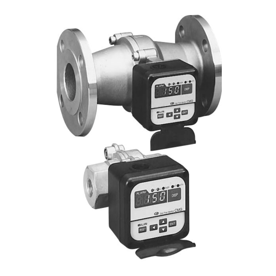
- Page 7 The CMG Gas Flow Monitor is a flowmeter for measuring the fuel flow rate of gas burners. It uses the Micro Flow sensor chip, a thermal mass flow sensor made using Azbil Corporation proprietary technology. The CMG measures and displays the instantaneous and integrated flow rate in normal standard state* without the need for temperature and pressure conversion.
- Page 8 Chapter 1. INTRODUCTION ■ Model selection guide VIII Model selection guide ● Air model Basic Description model Pipe Pipe Flow Output Pressure Commu- Power Additional size shape type range nication supply processing Gas flow monitor 15A (1/2B) 25A (1B) 40A (1 1/2B) 50A (2B) Rc thread JIS 10K flange (40A, 50A only)
- Page 9 *3 1 to 5 V output models have event output 1 (relay) but not event output 2 (open collector). For use of an integration pulse, select a 4 to 20 mA model. *4 For natural gas composition, refer to page 27. When using natural gas with a different composition, contact the azbil Group.
-
Page 10: Names And Functions Of Parts
Chapter 2. NAMES AND FUNCTIONS OF PARTS OVER indicator: Lights when the flow rate exceeds the measurement range. Blinks when the integration event occurs. Lo indicator: m indicator: Blinks when the lower limit alarm occurs. Lights during integrated flow rate display. Goes out during total flow rate display. -
Page 11: Mounting And Wiring
Chapter 3. MOUNTING AND WIRING WARNING When using combustible gas, nstall the device upstream of the safety shut off valve. If air somehow enters the piping, and the sensor makes a spark due to some cause like a lightning strike when an explosive mixture is present, an explosion could occur inside the pipe. - Page 12 Chapter 3. MOUNTING AND WIRING ■ Mounting ● Installation site Avoid mounting the CMG in locations characterized by the following: 1. Operating temperatures that fall below -10˚C and rise above 60˚C 2. Operating humidity that exceeds 90%RH 3. Sudden changes in temperature and condensation 4.
- Page 13 Chapter 3. MOUNTING AND WIRING ■ Behavior when the flowrate greatly exceeds the upper limit of flowrate range When the flowrate exceeds the upper limit of flowrate range, both the flowrate display and the output voltage/current may indicate lower values than the actual flowrate.
- Page 14 Recommended type: Name: Mist separator Model No.: MFF100 series Specifications: For details, refer to; Azbil Corporation's Specification seat (Japanese)CP-SS-1824. ● Straight pipe section To be sure the straight pipe section is long enough, refer to pages 27-28.
- Page 15 Chapter 3. MOUNTING AND WIRING ● Mounting position CAUTION • Do not mount so that the display is facing down. Doing so might cause error or other malfunction. • This device can be used with the display facing up ±90°. Right Right Right...
- Page 16 Chapter 3. MOUNTING AND WIRING ● Connecting pipes Connect pipes while gripping the hexagonal section of the pipe connection port on the body with a wrench. Pipe connection port Pipe Handling Precautions • Do not grip the display or sensor/terminal section. Doing so might damage the body or cause leakage.
- Page 17 Chapter 3. MOUNTING AND WIRING ● Flange Shape Use a flange that ensures a large contact area with the gasket. Good example Bad example Flange (Leakage may occur since the Welded part Welded part gasket contacting part is small.) Pipe ●...
- Page 18 Chapter 3. MOUNTING AND WIRING Tighten according to the torque in the following table: Aperture/Flange Rating Torque (N•m) 40mm JIS10K 22 to 32 50mm JIS10K 24 to 34 Handling Precautions • Tighten bolts so that they are uniformly tight. If leakage does not stop after tightening bolts, gradually tighten the bolts more a little at a time.
- Page 19 Chapter 3. MOUNTING AND WIRING ■ Wiring CAUTION Prevent the load connected to the output terminal from exceeding the rating indicated in the specifications. Failure to do so might cause damage. Be sure to check that the wiring is correct before you turn the power ON. Incorrect wiring might cause damage or malfunction.
- Page 20 • Use a JIS C 3401 control cable (CVV, etc.) of maximum outer diameter of 2.2mm for wiring. • If waterproofing is required, be sure to use the seal connector (Azbil Corporation model: PA4-N2, PA4-N4 or equivalent product) for reliable sealing.
- Page 21 Chapter 3. MOUNTING AND WIRING ● Mounting the operation panel/display On this device, the operation panel/display can be rotated up to 180˚ to an easy- to-view position. Follow the procedure below to mount the operation panel/display: 1. Connect the connectors of the leads from the operation panel/display to the sensor/terminal section.
-
Page 22: Operation
Chapter 4. OPERATION CAUTION Do not operate the keys with a mechanical pencil, screwdriver or other sharp-tipped object. Doing so might damage the keys. ■ Displaying the flow rate The following values can be alternated on the 4-digit, 7-segment LED display: 1. - Page 23 Chapter 4. OPERATION Handling Precautions • When the flow rate exceeds the upper limit of the measurement range, the OVER indicator light, and goes out after the flow rate returns to within the measurement range. • The integrated flow rate factory setting is 0. •...
- Page 24 Chapter 4. OPERATION ■ Displaying the total flow rate This function displays the total flow rate since the device was installed. Reset cannot be performed by the same reset operation used for integrated flow rate. (1) Press the key until the integrated flow rate is displayed. The m indicator lights.
-
Page 25: Application Operation
Chapter 5. APPLICATION OPERATION 5 - 1 Function Setup ■ Setting operation Follow the procedure below to set functions such as alarm detection and event output assignments. (1) Press the key to display the instantaneous flow rate. DISP The m /h indicator lights. - Page 26 Chapter 5. APPLICATION OPERATION ■ Function setup item list Item Item Description Settings and Description Remarks Displayed C-01 Key lock 0: Key lock disabled The key lock can be disabled even 1: All settings key-locked while it is enabled. C-02 Flow rate alarm 0: Alarm detection is not performed.
-
Page 27: Parameter Setup
Chapter 5. APPLICATION OPERATION 5 - 2 Parameter Setup ■ Setting operation Follow the procedure below to set parameters such as the flow rate alarm upper and lower limit values and alarm detection delay times. (1) Press the key to display the instantaneous flow rate. DISP The m /h indicator lights. - Page 28 Chapter 5. APPLICATION OPERATION ■ Parameter setup item list No. Item displayed Item Description Factory Setting Setting Range Remarks A. HI (*1) Instantaneous flow rate (Upper limit of (0 to 400% of Selection of an alarm upper limit alarm measurement range) measurement detection condition is upper limit)
- Page 29 Chapter 5. APPLICATION OPERATION ● Instantaneous flow rate upper limit alarm operation Hysteresis Instantaneous flow rate upper limit alarm value Instantaneous flow rate ● Instantaneous flow rate lower limit alarm operation Hysteresis Instantaneous flow rate lower limit alarm value Instantaneous flow rate...
-
Page 30: Maintenance And Troubleshooting
• If the connectors are free of abnormalities, a probable cause is sensor error. Contact the azbil Group as repair by Azbil Corporation is necessary. • The probable cause is an error in the memory, which is is displayed alternately individually adjusted for each sensor. - Page 31 Chapter 6. MAINTENANCE AND TROUBLESHOOTING ■ How to replace the fuse CAUTION When touching internal parts, touch a grounded metal part to discharge static electricity from the body. Otherwise, static electricity may damage components. Before replacing the fuse, be sure to turn the power OFF. Failure to do so might cause electric shock.
-
Page 32: Specifications
Chapter 7. SPECIFICATIONS ■ CMG Series specifications Item Specifications Applicable gas Natural gas (13A-46MJ/m ), air)(*1), air (according to model No.), propane (*2), butane (*3) Material Flow path section: aluminum alloy (Rc thread), SCS13 (flange) Display section: PBT (GF 30%) Instantaneous Natural gas Measurement range... - Page 33 Natural gas 13A-45MJ 45.007 88.9 When used for natural gas with a different composition than the above, contact the azbil Group. *2: Propane gas composition: propane 98%, (class B) *3: Butane gas composition: butane 75%, propane 25% ■ Individual CMG model specifications...
- Page 34 For all types of valves: 5D Ball valve: 10D Handling Precautions • If a governor, filter, or strainer disturbs the flow, contact the azbil Group. • Flow control valves, such as butterfly, needle, and globe valves, should be installed downstream of the CMG, at least 5D away from it.
- Page 35 Chapter 7. SPECIFICATIONS ■ Pressure loss ● For Rc thread, the data shows pressure loss for air. Primary pressure CMG150A004 CMG150N004 Atomospheric pressure CMG150P002 CMG150B001 50kPa 100kPa Flow rate [m /h (normal)] CMG250A010 CMG250N010 CMG250A030 CMG250N030 CMG250P010 CMG250B008 CMG250P004 CMG250B003 Flow rate [m /h (normal)] Flow rate [m...
- Page 36 Chapter 7. SPECIFICATIONS ● For air and city gas (13A) models with JIS10K flange, the data shows pressure loss for air. Primary pressure Atomospheric pressure 100kPa 300kPa 500kPa 700kPa CMG401A080_1 CMG401N080_1 CMG401A150_1 CMG401N150_1 1200 1000 Flow rate [m /h (normal)] Flow rate [m /h (normal)] CMG501A150_1 CMG501N150_1...
- Page 37 Chapter 7. SPECIFICATIONS ■ External dimensions Unit: mm ● CMG150/250 G 1/2 thread with min. depth 10 CMG250 Rc1 CMG150 Rc1/2 ● CMG400/500 G 1/2 thread with min. depth 10 CMG500 Rc2 CMG400 Rc1 1/2...
- Page 38 Chapter 7. SPECIFICATIONS ● CMG401 G 1/2 thread with min. depth 10 (4-19 hole) JIS 40A JIS 40A ● CMG501 OVER ALARM DISP Gas Flow Monitor G 1/2 thread with min. depth 10 (16) (14) JIS 50A JIS 50A...
-
Page 39: Revision History
Revision History Printed Manual Number Edition Revised pages Description date CP-SP-1113E 1st Edition July 2001 2nd Edition ii Description changed on the 2nd item in WARNING. Apr. 2003 Item added in CAUTION. iv, v Old iii, iv pages. *3 added to the medium pressure model. *3 description added. - Page 40 Printed Manual Number Edition Revised pages Description Date 25, 26 D: Connection piping size added. 6th Edition Dec. 2005 All page "Flowrate" to "Flow rate" changed. 7th Edition May 2005 "Zero adjustment" removed from the description of RESET key and ENT key. Description clarified.
- Page 41 Printed Manual Number Edition Revised pages Description Date 13th Edition ii CAUTION: Item 1, 2 added. Oct. 2007 ■Behavior when the flowrate greatly exceeds the upper limit of flowrate range added. 8 to 32 Old 7 to 31 pages. 14th Edition 2 *4 description added.
- Page 42 Specifications are subject to change without notice. (09) 1-12-2 Kawana, Fujisawa Kanagawa 251-8522 Japan URL: http://www.azbil.com 1st edition: July 2001 (W) 18th edition: Apr. 2012 (F)
Need help?
Do you have a question about the mF CMG Series and is the answer not in the manual?
Questions and answers