Table of Contents
Advertisement
Quick Links
Advertisement
Table of Contents
Troubleshooting

Related Manuals for Azbil MVC10A


Summary of Contents for Azbil MVC10A
- Page 1 CM2-MVC200-2001 The Multivariable Air Flow Meter Model MVC10A/10F User’s Manual...
- Page 2 In no event is Azbil Corporation liable to anyone for any indirect, special or consequential damages. This information and specifications in this document are subject to change without notice.
- Page 3 Azbil Corporation Preface Preface Thank you for purchasing our multivariable Air Flow Meter Model MVC10A/10F. This innovative flow meter that has been developed based on our long experience and expertise and has various functions including cost indication and leakage checking useful for energy-saving control in a wide variety of applications.
- Page 4 If you have any questions regarding the specifications, contact our branch and sales representative offices and your local Azbil Corporation distributor. When making an inquiry, be sure to let us know the Model and Product Nos. of the product you have purchased.
- Page 5 Denotes a potentially hazardous situation, which if not avoided, could result in death or serious injury. CAUTION Denotes a potentially hazardous situation, which if not avoided, could result in minor injury or property damage. Model: MVC10A/10F - Multivariable Air Flow Meter...
- Page 6 When looking for the explanations required for maintenance and troubleshooting, use this chapter as an information retrieval means. Appendix English and Japanese Messages Comparison Table Model: MVC10A/10F - Multivariable Air Flow Meter...
-
Page 7: Table Of Contents
Table of Contents Chapter 1: Configuration and structure of the measuring system Outline of this chapter ................1-1 1-1: System configuration ..................1-2 Measuring system ..................1-2 Introduction ................... 1-2 Concept of flow rate measurement ............1-2 System configuration of analog signal output (4 to 20 mA DC output) ..1-3 System configuration ................ - Page 8 Table of Contents 3-1: Startup ......................3-2 Activating this instrument ................3-2 Procedure ..................... 3-2 3-2: Preparatory operation before measurement ..........3-3 Introduction ................... 3-3 Method for zero adjustment ..............3-3 Introduction ................... 3-3 3-3: Stopping ......................3-4 Procedure ..................... 3-4 Chapter 4: Setting parameters and operating the local data setting device Outline of this chapter ................
- Page 9 Table of Contents Setting the language used for displayed messaged ......4-13 4-9: Setting during operation ................4-14 Introduction ................... 4-14 Switching the main displays ..............4-14 Setting or changing units ..............4-14 Setting or changing the damping time constant ........4-15 Setting or changing a low flow cut value ..........
- Page 10 Table of Contents...
-
Page 11: Chapter 1: Configuration And Structure Of The Measuring System
Chapter 1: Configuration and structure of the measuring system Outline of this chapter This chapter explains the measuring systems using this instrument. • The instrument’s structure and the names and functions of its integral parts are described. Model: MVC10A/10F - Multivariable Air Flow Meter... -
Page 12: Introduction
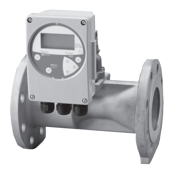
Figure 1-1 shows the outline of a flow-rate measuring system using this equipment. Converter Detector Fluid Analog output wiring inlet Power cable inlet Pulse output wiring inlet Fig. 1-1 Measuring system in an integral configuration Model: MVC10A/10F - Multivariable Air Flow Meter... -
Page 13: System Configuration Of Analog Signal Output (4 To 20 Ma Dc Output)
This instrument: Measures flow-rate and outputs instantaneous flow-rate values in analog signals (4 to 20 mA DC). • The analog output range is 3.8 mA to 20.8 mA DC (-1.25% to +105%). • The load resistance is 245 to 300W Model: MVC10A/10F - Multivariable Air Flow Meter... -
Page 14: 1-2: Structure And Functions Of Components
Power unit cover mounting screws (4 x M3) Terminal board mounting screws (4 x M3) Tag plate Main board Terminal board Terminal block Power unit cover Fuse Fig. 1-4 Structure of converter case Model: MVC10A/10F - Multivariable Air Flow Meter... -
Page 15: Name And Function Of Each Part
Nameplate • Model No., Product No., and flow-rate range are described on it. Tag No. plate • A Tag No. is indicated when specified by the purchase order. Model: MVC10A/10F - Multivariable Air Flow Meter... - Page 16 Configuration and structure of the measuring system Azbil Corporation Model: MVC10A/10F - Multivariable Air Flow Meter...
-
Page 17: Chapter 2: Installation Of This Instrument
Azbil Corporation Installation of this instrument Chapter 2: Installation of this instrument Outline of this chapter This chapter describes the method for installation and wiring of this instrument. Model: MVC10A/10F - Multivariable Air Flow Meter... -
Page 18: 2-1: Before Starting Installation
This instrument has an oval orifice in the pipe, and the service direction is specified. Allow the work fluid to flow in the direction of the arrow marked on the side of the detector. Model: MVC10A/10F - Multivariable Air Flow Meter... - Page 19 CAUTION Since the work fluid contains more or less water, remove the accumulated water inside the remote type tube and pressure-bearing cover of the body. Otherwise, an output shift may result. Model: MVC10A/10F - Multivariable Air Flow Meter...
-
Page 20: 2-2: Installation Method
If it is dropped by mistake, you may be wounded or suffer a broken bone. Bore diameter 50 A 65 A 80 A 100 A 150 A Weight 9 kg 11 kg 13 kg 18.5 kg 39.5 kg Model: MVC10A/10F - Multivariable Air Flow Meter... -
Page 21: Connection With Remote Type Converter
When cutting a tube, ensure that the tube is not collapsed. • The bend radius of the tube is not so small as 15 mm or less. • When mounting the tube on the fitting, ensure that it is securely pushed in. Model: MVC10A/10F - Multivariable Air Flow Meter... -
Page 22: 2-3: Electrical Wiring
• Never perform wiring while the system is energized. Otherwise an electric shock may occur. Note: • Follow the indication for connecting positions and perform the wiring correctly. Otherwise equipment failure may result. • Power source lines in particular carry a large-capacity power, double-check the wiring positions. Model: MVC10A/10F - Multivariable Air Flow Meter... -
Page 23: Cable Specifications
Internal terminals output the current. 4-20 mA DC analog signal Receiving instrument This instrument Fig. 2-6 Diagram of wire connection of current output Note: Incorrect wiring polarity can cause damage to the equipment. Double-check the wiring position. Model: MVC10A/10F - Multivariable Air Flow Meter... -
Page 24: Wiring Connection Of Pulse Output
Fig. 2-7 Pulse output wire connection diagram CAUTION • Incorrect wiring polarity can cause damage to the equipment. Double-check the wiring position. • Use an external power source that meets the voltage and capacity specifications. Model: MVC10A/10F - Multivariable Air Flow Meter... -
Page 25: Chapter 3: Operation And Shut Down Of This Instrument
Thus, before starting the operation, switch the language for display to “English.” For the details of changing languages for display, refer to the Item “Setting the language for display” under Subsection 4-8, “Initial setting.” Model: MVC10A/10F - Multivariable Air Flow Meter... -
Page 26: 3-1: Startup
Fill this instrument with the fluid to be measured and let it stay still for a while. Ensure that no leakage is found from the flanges on which this instrument is fitted. Energize the converter for this instrument. Ensure that LCD display is activated. Model: MVC10A/10F - Multivariable Air Flow Meter... -
Page 27: 3-2: Preparatory Operation Before Measurement
• “Sensor Range Over” This message appears when the present value exceeds the sensor range. If this message is displayed, contact our sales representatives' office, your distributor, or our customer services department directly. Model: MVC10A/10F - Multivariable Air Flow Meter... -
Page 28: 3-3: Stopping
To stop the operation of this instrument, use the following procedure: Step Procedure Switch the operation mode of the control unit for the instrument to be stopped to manual control. Turn off the power supply for the instrument. Model: MVC10A/10F - Multivariable Air Flow Meter... -
Page 29: Chapter 4: Setting Parameters And Operating The Local Data Setting Device
Thus, before starting the operation for this chapter, switch the language for display to “English.” For the details of changing languages for display, refer to the Item “Setting the language for display” under Subsection 4-8, “Initial setting.” Model: MVC10A/10F - Multivariable Air Flow Meter... -
Page 30: Names And Description Of Parts
• Allows the key to be locked. (Keep pressing it for 3 seconds.) • Inputs values. • Selects setting menus. CAUTION Never press a key with a pencil, ball-point pen, or any other objects having a sharp tip, which may damage the key. Model: MVC10A/10F - Multivariable Air Flow Meter... -
Page 31: Name And Description Of Display Parts
2) Flow Flow Rate 2) Flow Flow Rate 3) T.Cost, Cost Total Cost, Cost 3) T.Cost, Cost Total Cost, Cost 4) %Output %Output (Flow) 4) %Output %Output (Flow) 5) Velocity Velocity 6) Pressure Pressure Model: MVC10A/10F - Multivariable Air Flow Meter... -
Page 32: 4-2: Details Of Operation Using The Display Of The Local Data Setting Device
Leaving the keys without operating them for 3 minutes allows the system to turn off the illumination automatically. • When the keys are left untouched for 3 minutes, automatically switches the system to measuring mode. Model: MVC10A/10F - Multivariable Air Flow Meter... -
Page 33: 4-3: Description Of The Measuring Mode
* Pressing the [Disp.] (D) key while operating in the setting menu switches the mode to the measuring mode. Thus, when values of each item are being changed, pressing the [Disp.] key (D) cancels the values. Model: MVC10A/10F - Multivariable Air Flow Meter... -
Page 34: 4-5: Configuration Of The "Basic Menu
Selects the unit for an instantaneous cost value. 5 <Leak Check> 1 <Leak Rate> Displays a leak rate. Displays and sets a leak rate. 2 <Reset OK?> Resets measured data. 3 <Set Press> Sets a compressor pressure. Model: MVC10A/10F - Multivariable Air Flow Meter... -
Page 35: 4-6: Configuration Of The "Maintenance Menu
8 <Max Flow> Deletes the given maximum flow rate. Sets the maximum value to an arbitrary value. 9 <DAC Trim> Trims an analog output value. 10 <Language> Sets the language used for display. Model: MVC10A/10F - Multivariable Air Flow Meter... -
Page 36: 4-7: Method Of Operation By Using The Setting Menu Mode
(3) After changing the menu settings, press the [Enter] key (E) to implement the set details. < > Press the Enter key (E). This message appears. * To cancel the changes, press the [Menu] key (M) or [Disp.] key (D). Model: MVC10A/10F - Multivariable Air Flow Meter... -
Page 37: Changing Figures Within The Setting Menu
(3) Press the [Enter] key (E) to implement the set details. < > Press the Enter key (E). This message appears. * When the set figure is beyond the range of setting, an error message appears. Model: MVC10A/10F - Multivariable Air Flow Meter... -
Page 38: 4-8: Initial Setting
After inputting the reference pressure, press the Enter key (E). When the message “Value Changed” appears, the setting is completed. Note: • The value of reference pressure represents the absolute pressure. 4-10 Model: MVC10A/10F - Multivariable Air Flow Meter... -
Page 39: Setting The Pulse Weights
When changing the unit of totalized cost, the value of cost weight (or cost rate) is set to “0.” * For the details of cost, refer to Chapter 4, Subsection 4-11, “Explanation on some important functions,” Cost indicating function. Model: MVC10A/10F - Multivariable Air Flow Meter 4-11... -
Page 40: Executing The Zero Adjustment
When setting the maximum flow rate to an arbitrary value, refer to the next Item, “Setting the maximum flow rate value.” • For the details of the auto ranging function, refer to Chapter 4, Subsection 4-11, “Explanation on some important functions,” Automatic ranging function. 4-12 Model: MVC10A/10F - Multivariable Air Flow Meter... -
Page 41: Setting The Maximum Flow Rate Value
Select the language to be displayed by using the key to enter the tag. Then, press the [Enter] key (E). When the message “Value Changed” appears, the setting is completed. Model: MVC10A/10F - Multivariable Air Flow Meter 4-13... -
Page 42: 4-9: Setting During Operation
• When the totalized unit is changed, the totalized value is reset. • The unit for pressure is fixed to MPa (gauge pressure) and that of flow velocity is fixed to m/s. 4-14 Model: MVC10A/10F - Multivariable Air Flow Meter... -
Page 43: Setting Or Changing The Damping Time Constant
“1: Leak Rate” cursor. Select the items to be set by using the key. Note: The value of set pressure in the leak check function represents the gauge pressure. Model: MVC10A/10F - Multivariable Air Flow Meter 4-15... -
Page 44: Details Of Default Settings
Ref. Pressure 101.325 kPa (abs) Pulse Weight Customer-specified value (When unspecified: 0.1 m /pulse) Cost Rate 0 yen/m Customer-specified value (When unspecified, maximum Max Flow value for the given bore) Language Japanese 4-16 Model: MVC10A/10F - Multivariable Air Flow Meter... -
Page 45: Explanation On Some Important Functions
Cost (yen/h) = B (yen/m ) × A (m Similarly, total cost (cumulative cost) can be calculated as follows: Total cost (yen) = B (yen/m ) × Total flow rate (cumulative flow rate, m Model: MVC10A/10F - Multivariable Air Flow Meter 4-17... -
Page 46: Auto Ranging Function
• When reference temperature and pressure have been changed, since the details of internal flow rate calculations are altered, delete the maximum flow rate value in the operation “Del Rate Value.” 4-18 Model: MVC10A/10F - Multivariable Air Flow Meter... -
Page 47: Leak Checking Function
“Leak Check” - “2 <Reset OK?>.” (3) Setting of the above-mentioned compressor pressure can be conducted by using the process “Leak Check” - “3 <Set Press>.” The allowable pressure setting range is 0.30 to 0.98 MPa. Model: MVC10A/10F - Multivariable Air Flow Meter 4-19... - Page 48 Setting parameters and operating the local data setting device Azbil Corporation 4-20 Model: MVC10A/10F - Multivariable Air Flow Meter...
-
Page 49: Chapter 5: Maintenance And Troubleshooting Of This Instrument
Chapter 5: Maintenance and troubleshooting of this instrument Outline of this chapter This chapter enumerates the steps for maintenance and inspection of this instrument and the matters that should be referred to when conducting troubleshooting. Model: MVC10A/10F - Multivariable Air Flow Meter... -
Page 50: 5-1: Maintenance
When fixing the terminal with screws, pay attention to avoid excessive screw tightening that may damage them. Also take necessary care not to pinch the cable connecting the FPC and LCD with screws or the cover. Model: MVC10A/10F - Multivariable Air Flow Meter... -
Page 51: Disassembling And Assembling The Converter And Its Fixture
(G) • 20 Megaohms minimum at 100 V DC Across the current output terminal (I+ terminal and I- terminal short-circuited) and grounding terminal (G) • 20 Megaohms minimum at 100 V DC Model: MVC10A/10F - Multivariable Air Flow Meter... -
Page 52: Withstand Voltage
(5) Bring back the fuse holder cover to the original position. (6) Attach the covers for the main body and the power supply unit in the original way. (7) Start the power supply through the terminals L and N of this instrument. Model: MVC10A/10F - Multivariable Air Flow Meter... -
Page 53: 5-2: Troubleshooting
• Ensure that the polarity of detector terminals and connection of the converter are correct. Model: MVC10A/10F - Multivariable Air Flow Meter... -
Page 54: Troubles During Operation
Pulse output value is excessive • Ensure that correct specifications for pulse counter are relative to the flow rate. used. • Ensure that the value of low flow cut is correctly set. Model: MVC10A/10F - Multivariable Air Flow Meter... -
Page 55: Display And Output State Beyond The Range Of Flow Rate Measurement
Use the measured Use the Leak check flow. (Specified in the value value measured value User's Manual.) Auto ranging (peak Do not used the Use the measured Use the value) measured value. value measured value Model: MVC10A/10F - Multivariable Air Flow Meter... -
Page 56: Error Messages And Corrective Actions
Description of error CHAR PROM FAULT Abnormality in internal data SUSPECT INPUT Abnormality in sensor output NVM FAULT NVM abnormality RAM FAULT Abnormality in an internal RAM ROM FAULT Abnormality in an internal ROM Model: MVC10A/10F - Multivariable Air Flow Meter... -
Page 57: Appendix English And Japanese Messages Comparison Table
Leak-checking measured values resetting Set. Press Internal pipe systems pressure setting Tag setting Ref. Temp Reference temperature setting Ref. Pressure Reference pressure setting Pulse Weight Pulse weight setting Cost Rate Cost weight setting Model: MVC10A/10F - Multivariable Air Flow Meter Appendix-1... - Page 58 Cumulative values resetting re-confirmation Completely! Cumulative values resetting completed Message appearing at set value changing Value changed! An input value has been set Input Value Error Error message for an excessive value of input Appendix-2 Model: MVC10A/10F - Multivariable Air Flow Meter...
- Page 60 Warranty period and warranty scope 1.1 Warranty period Azbil Corporation’s products shall be warranted for one (1) year from the date of your purchase of the said products or the delivery of the said products to a place designated by you.
- Page 61 Although acceleration of the above situation varies depending on the conditions or environment of use of the products, you are required not to use any Azbil Corporation’s products for a period exceeding ten (10) years unless otherwise stated in specifications or instruction manuals.
- Page 63 Document Number: CM2-MVC200-2001 Document Name: The Multivariable Air Flow Meter Model MVC10A/10F User's Manual Date: 1st edition: April 2006 3rd edition: Jan. 2020 Issued/Edited by: Azbil Corporation...
Need help?
Do you have a question about the MVC10A and is the answer not in the manual?
Questions and answers