Sign In
Upload
Manuals
Brands
Azbil Manuals
Measuring Instruments
MagneW FLEX+
Azbil MagneW FLEX+ Flowmeter Converter Manuals
Manuals and User Guides for Azbil MagneW FLEX+ Flowmeter Converter. We have
2
Azbil MagneW FLEX+ Flowmeter Converter manuals available for free PDF download: User Manual
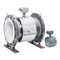
Azbil MagneW FLEX+ User Manual (88 pages)
Electromagnetic Flowmeter Detector
Brand:
Azbil
| Category:
Measuring Instruments
| Size: 4 MB
Table of Contents
Table of Contents
7
Chapter 1 : Introduction
15
Principle of Operation
15
Figure 1-1 Faraday's Law
15
System Operation
16
1: Integral Type
16
Figure 1-2 Integral Configuration
16
2: Remote Type
17
Figure 1-3 Remote Configuration
17
Main Components
18
1: Wafer Type Detector
19
Figure 1-4 Wafer Detector Main Parts
19
2: Flange Type Detector
20
Figure 1-5 Flange Detector Main Parts
20
3: Union / Hose / Clamp Type Detector
21
Figure 1-6 Union / Hose / Clamp Detector Main Parts
21
4: Sanitary Type Detector
22
Figure 1-7 Details of the Clamp Type Detector
22
5: Detector Terminal Box
23
Figure 1-8 Detector Terminal Box Main Parts
23
6: Approval of this Device
24
Chapter 2 : Installation
27
Unpacking
27
1: Verifying Specifications
27
Storage
28
Site Selection
29
1: Detector Position
30
Figure 2-1 Detector Placement
30
Figure 2-2 Straight Pipe Section on Upstream Side of Detector
30
2: Changing the Position of the Terminal Box
31
Figure 2-3 Space Allowance Required for Maintenance
31
Figure 2-4 Repositioning the Terminal Box
31
Installing a Wafer Detector
32
Figure 2-5 Installing a Wafer Detector
32
1: Determining the Fastening Torque
33
2: Selecting the Flange Shape
33
Figure 2-6 Flange Shapes
33
Table 2-1 Fastening Torque for Wafer Detectors
33
Figure 2-7 Unacceptable Positioning
34
Figure 2-8 Unacceptable Placement of Detector between Flanges
34
3: Necessary Parts
35
Figure 2-10 Centering Nut Positioning for Vertical Centering
35
Figure 2-9 Centering Nut Positioning for Horizontal Centering
35
Table 2-2 Recommended Inner Diameters of Gaskets
36
Table 2-3 Inner and Outer Diameters of Rubber Gaskets of Thickness 0.5 to 1 MM (0.02 to 0.04 Inches)
37
Table 2-4 Inner and Outer Diameters of Rubber Gaskets of Thickness 3 to 4 MM (0.12 to 0.16 Inches)
37
4: Selecting an Installation Method
38
Table 2-5 Wafer Detector Installation Methods
38
5: Installation on a Horizontal Pipe
39
6: Installation on a Vertical Pipe
40
7: Installation on a Metal Pipe Using SUS Grounding Ring Material
41
Figure 2-11 Installation on a Metal Pipe Using SUS Grounding Ring Material and a Specified Torque
41
8: Installation on a Metal Pipe Using Non-SUS Grounding Ring Material
42
Figure 2-12 Installation on a Metal Pipe Using Non-SUS Grounding Ring Material and a Specified Torque
42
Figure 2-13 Installation on a Metal Pipe Using Non-SUS Grounding Ring Material with Rubber Gaskets
43
Figure 2-14 Incorrect Installation
44
9: Installation on a PVC Pipe Using SUS Grounding Ring Material
45
Figure 2-15 Installation on a PVC Pipe Using SUS Grounding Ring Material
45
Figure 2-16 Installation on a PVC Pipe Using SUS Grounding Ring Material and a Protective Plate
46
Figure 2-17 Installation on a PVC Pipe Using SUS Grounding Ring Material with Rubber Gaskets (Not Recommended)
47
10: Installation on a PVC Pipe Using Non-SUS Grounding Ring Material
48
Figure 2-18 Installation on a PVC Pipe Using Non-SUS Grounding Ring Material
48
Figure 2-19 Installation on a PVC Pipe Using Non-SUS Grounding Ring Material and a Protective Plate
49
Figure 2-20 Installation on a PVC Pipe Using Non-SUS Grounding Ring Material with Rubber Gaskets
50
Installing a Flanged Detector
51
Figure 2-21 Installing a Flanged Detector
51
1: Determining the Fastening Torque
52
Table 2-6 Fastening Torque for Flanged Detectors
52
Table 2-9 Fastening Torque
53
Figure 2-22 Flange Shapes
56
Figure 2-23 Unacceptable Placement of Detector between Flanges
56
2: Necessary Parts
57
Table 2-7 Recommended Inner Diameters of Gaskets
57
3: Selecting an Installation Method
58
Table 2-8 Flange Detector Installation Methods
58
4: Installation on a Metal Pipe Using SUS Grounding Ring Material
59
Figure 2-24 Installation on a Metal Pipe Using SUS Grounding Ring Material and a Specified Torque
59
5: Installation on a Metal Pipe Using Non-SUS Grounding Ring Material
60
Figure 2-25 Installation on a Metal Pipe Using Non-SUS Grounding Ring Material and a Specified Torque
60
6: Installation on a PVC Pipe Using SUS Grounding Ring Material
61
Figure 2-26 Incorrect Installation
61
Figure 2-27 Installation on a PVC Pipe Using SUS Grounding Ring Material and a Specified Torque
62
Figure 2-28 Installation on a PVC Pipe Using SUS Grounding Ring Material and a Protective Plate
63
Figure 2-29 Installation on a PVC Pipe Using SUS Grounding Ring Material with Rubber Gaskets (Not Recommended)
64
7: Installation on a PVC Pipe Using Non-SUS Grounding Ring Material
65
Figure 2-30 Installation on a PVC Pipe Using Non-SUS Grounding Ring Material and a Specified Torque
66
Figure 2-31 Installation on a PVC Pipe Using Non-SUS Grounding Ring Material and a Protective Plate
67
Figure 2-32 Installation on a PVC Pipe Using Non-SUS Grounding Ring Material with Rubber Gaskets
68
Installing a Union / Hose / Clamp Detector
69
1: Installation of Union and Hose Assemblies Basic Installation Method
69
2: Installation of ISO-Clamp/ Tri-Clamp Assembles Basic Installation Method
70
Figure 2-33 Example of Installation (Union Assembly)
70
Figure 2-34 Example of Installation
70
Wiring the Detector
72
1: Connecting the Detector and Converter (Remote Models)
72
Figure 2-35 Connection Using a Dedicated Cable
72
2: Grounding the Detector (Remote Models)
73
3: Installing the Dedicated Cable
73
Figure 2-36 Grounding Via the External Grounding Terminal
73
Figure 2-37 Connection Using a Dedicated Cable
73
Figure 2-38 Dedicated Cable Structure
74
Figure 2-39 Trimming the Outside Sheath
74
Figure 2-40 Attaching the C-Wire
75
Figure 2-41 Trimming the Outside Shield
75
Figure 2-42 Trimming the Inside Sheath
76
Figure 2-43 Attaching the Lead Wires (SA and SB)
76
Figure 2-44 Trimming the Inside Shield
77
Figure 2-45 Removing the Conductive Tube
77
Figure 2-46 Trimming the Insulator
77
Figure 2-47 Terminal Connections
78
Table 2-10 Cable Continuity
78
Table 2-11 Cable Continuity
78
Figure 2-48 Trimming the Outside Sheath
79
Figure 2-49 Attaching the C-Wire
79
Figure 2-50 Trimming the Outside Shield
80
Figure 2-51 Trimming the Inside Sheath
80
Figure 2-52 Attaching the Lead Wires (SA and SB)
80
Figure 2-53 Attaching the Lead Wires (SA and SB)
81
Troubleshooting and Maintenance
82
Figure 2-54 Terminal Connections
82
Table 2-12 Cable Continuity
82
Table 2-13 Cable Continuity
82
Advertisement
Azbil MagneW FLEX+ User Manual (74 pages)
Electromagnetic Flowmeter Explosion-proof type Detector
Brand:
Azbil
| Category:
Measuring Instruments
| Size: 2 MB
Table of Contents
Table of Contents
7
Chapter 1 - Configuration and Structure of the Measuring System
10
Introduction
10
1-1 System Configuration
11
Measuring System
11
Figure 1-1 Integral Configuration
11
1-2 Structure of this Unit and Functions of Parts
12
Detector
12
Detector Terminal Box
17
Figure 1-6 Detector Terminal Box
17
Use of Explosion-Proof Electromagnetic Flowmeters for TIIS
18
Use of Explosion-Proof Electromagnetic Flowmeters for FM/CSA
20
Chapter 2 - Installing the Device
22
Introduction
22
2-1 before Installing
23
Criteria for Selecting the Installation Site
23
Figure 2-1 Proper Placement of the Detector
25
Figure 2-2 Straight Pipe Section on the Upstream Side of the Detector
25
Figure 2-3 Space Allowance for Inspections
26
Directions of the Terminal Box and the Converter
27
Figure 2-4 Repositioning the Terminal Box or Converter
28
2-2 Method of Installation
29
Installing a Wafer Detector
29
Basic Installation Method
29
Figure 2-5 Device Installation Example
29
Figure 2-6 Flange Shape
30
Figure 2-7 Examples of Unacceptable Installation (1)
31
Parts Necessary for Installation
32
Figure 2-9 Horizontal Centering of the Detector
32
Figure 2-10 Vertical Centering of the Detector
32
Table 2-2 Recommended Inner Diameters of Gaskets
33
Selecting an Installation Method
34
Figure 2-11 Installation Using SUS Material Grounding Ring and Metal Pipe
39
Installation on a Pipe
40
Figure 2-12 Installation Using Non-SUS Material Grounding Ring and Metal Pipe
41
Figure 2-13 Example of Incorrect Installation
41
Figure 2-14 Installation Using SUS Material Grounding Ring
43
Figure 2-15 Installation Using SUS Material Grounding Ring (with Protective Plate)
44
Figure 2-17 Installation Using the Grounding Ring of Non-SUS Material
45
Figure 2-18 Installation Using the Grounding Ring of Non-SUS Material (with Protective Plate)
46
Installing a Flanged Detector
47
Basic Installation Method
47
Figure 2-20 Installation Example
47
Table 2-5 Fastening Torque
48
Figure 2-21 Flange Shape
51
Figure 2-22 Example of Incorrect Mounting
52
Parts Necessary for Installation
53
Selecting an Installation Method
54
Installation on a Pipe
55
Figure 2-23 Installation Using Grounding Rings of SUS Material
55
Figure 2-24 Installation Using Grounding Ring Made of Non-SUS Material
57
Figure 2-25 Example of Incorrect Installation
57
Figure 2-26 Installation Using SUS Material Grounding Ring
59
Figure 2-27 Detector Installation Using SUS Material Grounding Ring (with Protective Plate)
60
Figure 2-29 Detector Installation Using Non-SUS Material Grounding Ring
61
Figure 2-30 Detector Installation Using Non-SUS Material Grounding Ring (with Protective Plate)
62
Electrical Wiring
63
Figure 2-33 Grounding Via the External Grounding Terminal
64
Chapter 3 - Maintenance of the Device
66
Introduction
66
Index
68
Advertisement
Related Products
Azbil MagneW PLUS+
Azbil MagneW Plus+ Series
Azbil MagneW Neo PLUS
Azbil MagneW Two-wire PLUS+
Azbil MGG15
Azbil MGG18
Azbil MVF150
Azbil MCF0250
Azbil MCB10A
Azbil mF MVF080
Azbil Categories
Controller
Control Unit
Measuring Instruments
Transmitter
Switch
More Azbil Manuals
Login
Sign In
OR
Sign in with Facebook
Sign in with Google
Upload manual
Upload from disk
Upload from URL