
Related Manuals for Azbil MCB10A


Summary of Contents for Azbil MCB10A
- Page 1 Electromagnetic Flowmeter for Water Measurement Model: MCB10A User’s Manual CM2-MCB100-2001 3rd edition...
- Page 2 In no event is Azbil Corporation liable to anyone for any indirect, special or consequential damages. This information and specifications in this document are subject to change without notice.
- Page 3 Preface Thank you for purchasing our electromagnetic flowmeter. The model MCB is a flowmeter dedicated to water flow measurement and was developed applying the basic principle of electromagnetic flow measurement to be an inexpensive, easy-to- use instrument. Model MCB10A...
- Page 4 • Flange rating Inquiries If you have any questions regarding the specifications, contact the nearest Azbil Corporation office or Azbil Corporation representative service offices. When making an inquiry, be sure to provide the MODEL NO. and PRODUCT NO. Storage precautions When storing this instrument before use, observe the following precautions: •...
- Page 5 Safety About this manual This manual contains information and warnings that must be observed to keep the model MCB10A electromagnetic flowmeter operating safely. Correct installation, correct operation and regular maintenance are essential to ensure safety while using this device. For the correct and safe use of this electromagnetic flowmeter, it is essential that both operating and service personnel follow generally accepted safety procedures in addition to the safety precautions specified in this manual.
- Page 6 DO NOT use the electromagnetic flowmeter to ground a welder. It can damage the electromagnetic flowmeter. CAUTION The detector must be grounded (grounding resistance is < 100 W) to avoid output fluctuation, zero point instability or output drift. Model MCB10A...
- Page 7 The correct fastening torque must be used to prevent leakage. To avoid damage to the detector, do not exceed the listed fastening torque. CAUTION Before installing the detector, make sure that the pipe is exactly straight and centered. Any irregularity could cause leakage or other hazards. Model MCB10A...
- Page 8 Insufficient grounding can cause output fluctuations, instability of the zero point, or output drift. Secure single point grounding with a grounding resistance of 100 W or less is recommended. Do not ground a welder to the detector to avoid damaging the detector. Model MCB10A...
-
Page 9: Table Of Contents
Table of Contents Chapter 1 : Configuration and structure of measuring system Outline of this chapter ....................1-1 1-1 : Loop configuration ................. 1-2 1-1-1 : Measuring system ......................1-2 1-1-2 : Loop configuration for analog output ................1-3 1-1-3 : Loop configuration for pulse output ..................1-4 1-1-4 : Loop configuration for contact output ................1-5 1-2 :... - Page 10 Table of Contents Chapter 5 : Operation using the data setting device 5-1 : Startup ..................... 5-2 5-1-1 : Display and operation contents of data setting device .............5-3 5-2 : Functions of the data setting device ............ 5-5 5-2-1 : Data setting device......................5-5 5-3 : Description of MEASURING MODE ............
- Page 11 Table of Contents 5-8-2 : Non-critical error......................5-54 5-8-3 : Status indication ......................5-55 Chapter 6 : Maintenance and troubleshooting Outline of this chapter ....................6-1 6-1 : Maintenance and inspection of hardware ..........6-2 6-1-1 : Replacement of indicator/data setter ................6-2 6-2 : Troubleshooting ..................
- Page 12 List of Figures & Tables <Figures & Photographs> Figure 1-1 Conceptual drawing of measuring system (integral type) ..............1-2 Figure 1-2 Loop configuration for analog output ....................1-3 Figure 1-3 Loop configuration for pulse output ....................1-4 Figure 1-4 Loop configuration for contact output ....................1-5 Figure 1-5 General view of integral type ......................1-6 Figure 1-6 Detector details (wafer-type) ......................1-7 Photograph 1-1 Indicator/data setter details .......................1-8...
-
Page 13: Outline Of This Chapter
Chapter 1 : Configuration and structure of measuring system Outline of this chapter This chapter presents the equipment configuration of a measuring system using this instrument. • It also describes the structure, the names and functions of various parts of the main unit. Model MCB10A... -
Page 14: Loop Configuration
Hz can be delivered. The pulse output can be delivered simultaneously with an analog output. Contact output Instead of the pulse output, a contact output is available using the open-collector output. The contact output can be delivered simultaneously with an analog output. Model MCB10A... -
Page 15: Loop Configuration For Analog Output
When configuring a system using this instrument, it is necessary to determine the supply power voltage and load resistance to satisfy the operation conditions of this instrument. For details, refer to Specification Sheet. Model MCB10A... -
Page 16: Loop Configuration For Pulse Output
Electronic counter: Receives the pulse output as input and displays the totalized value. Batch or other types of control take place based on the totalized value on the electronic counter. • Open collector: A pulse output method using a transistor contact. Model MCB10A... -
Page 17: Loop Configuration For Contact Output
Electromagnetic flowmeter (main unit): Measures flow rate and outputs an upper or lower limit alarm or critical failure as a contact output. • Contact input equipment: Receives the contact output and displays the alarm and the like. • Open collector: An output method using a transistor contact. Model MCB10A... -
Page 18: Structure Of This Instrument And Functions Of Its Various Parts
• Transforms the signal of electromotive force generated by the sensor into an instantaneous flow rate value and outputs a flow rate signal. Equipped inside with a Terminal block. Indicator/data setter • Displays the instantaneous flow rate value and internal status of the instrument. Model MCB10A... -
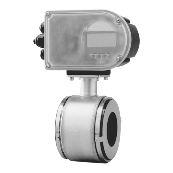
Page 19: Detector: Wafer Type
The following table describes the various parts of the detector. Name Description Flow direction mark • Indicates the flow direction of the fluid. • Install the detector and ensure that the fluid flow conforms to the flow direction mark. Grounding ring • Made of stainless steel Model MCB10A... -
Page 20: Indicator/Data Setter
The indicator face can be turned at intervals of 90 degrees through one turn. Names of various parts The names of various parts of the indicator/data setter are shown. Setscrew Liquid crystal display Photograph 1-1 Indicator/data setter details Model MCB10A... -
Page 21: Terminal Block
Names of various parts The structure of the terminal block and the manes of its various parts are shown. Connecting cable gland Power terminal Grounding terminal for output line conduit Output signal terminal Photograph 1-2 Indicator/data setter details Model MCB10A... - Page 22 • The grounding should be JIS Class D. If not grounded, malfunctions can result. Connecting cable • Wire the signal line by entering it through this. gland for output signal line conduit 1-10 Model MCB10A...
-
Page 23: Chapter 2 : Instrument Installation
The necessary components and installing methods depend on the material of the grounding ring and the material of the installed piping. The description proceeds in the following order: • Criteria for selecting an installation environment • Outline of installing method of the instrument • Detailed installing methods by materials Model MCB10A... -
Page 24: Before Installation
(2) Some fluids with a surfactant mixed in (For example, rinse, shampoo and CWM) (3) Insulating adhesive materials (For example, oil, kaolinite, kaolin, calcium stearate) (4) Slurry fluids containing solid matter (For example, pulp slurry, mud slurry, cement slurry) Model MCB10A... - Page 25 Otherwise, you may be injured. • The output signal or indication may fluctuate depending on pulsation or other conditions of the fluid. In such cases, increase the damping time constant or take some other measure. Model MCB10A...
-
Page 26: Criteria (2) For Selecting An Installation Location
5D or over 5D or over section) Detector Gate valve Detector Valve of fully open various types 5D or over 10D or over Figure 2-2 Straight pipe section upstream of detector (D: Nominal detector bore diameter) Model MCB10A... - Page 27 Choose a place where there are little pulsations in the flow (install at a place sufficiently distant from a pump or the like). • Ensure the necessary space for inspecting the terminal box. Figure 2-3 Necessary space for inspection Model MCB10A...
-
Page 28: Direction Of Indicator/Data Setter
When tightening the screws, take care not to entangle and squeeze the cable. Attach the front cover. ~Note Take care not to injure your fingers on the cover edge or the thread in the case. Figure 2-4 Changing the indicator/data setter direction Model MCB10A... -
Page 29: Direction Of The Converter
Using a hex wrench, re-tighten the four screws to secure the converter. Hex wrench Figure 2-5 Repositioning the converter CAUTION After removing the screws, do not pull hard on the converter. Otherwise, the lead wire inside can break. Model MCB10A... -
Page 30: Installation Method
SUS material. For other material, a gasket comes with it) Figure 2-6 Example of installation CAUTION This instrument is heavy. Dropping it on your foot may cause injury or bone fracture. Take due care. Model MCB10A... - Page 31 Do not touch the electrodes with your hand, an oily rag or the like. Otherwise, output fluctuations may result. • Make the flow direction mark of the detector agree with the direction of the fluid flow. In case of disagreement, no output will be delivered. Model MCB10A...
- Page 32 If fluid leakage does not stop after tightening, check for misalignment and gradually increase the tightening bolt. When installing, take care that the tightening bolt is within the prescribed limit. Otherwise, damaged equipment may result. 2-10 Model MCB10A...
-
Page 33: Components Necessary For Installation
For the attaching position, see the following figures. Flange Centering nuts Figure 2-10 Horizontal mounting (Attach two pieces to each of the right and left flanges.) Flange Centering nuts Figure 2-11 Vertical mounting (Attach 4 pieces to the lower flange.) Model MCB10A 2-11... - Page 34 100 mm Size (1/2 inch) (1 inch) (1½ inch) (2 inches) (2½ inches) (3 inches) (4 inches) 16.5 25.5 40.5 Internal diameter ±1 ±1 ±1 ±1 ±1 ±1 ±1 External diameter ±1 ±1 ±1 ±1 ±1 ±1 ±1 2-12 Model MCB10A...
-
Page 35: Selecting An Installing Method
Selecting an installing method by material Choose the appropriate installing method according to the following table. Material of pipe on which to install Material of grounding ring Page to refer to Metal SUS material Page 2-17 SUS material Page 2-18 Model MCB10A 2-13... -
Page 36: Installing Method On A Horizontal Pipe
Fluid flow direction • Check for misalignment. • Check the gaskets for flushness. • On completion of these checks, pass the remaining bolts through the flange holes and tighten all bolts evenly with the tightening torque on page 2-9. 2-14 Model MCB10A... -
Page 37: Installing Method On A Vertical Pipe
Terminal box side Flange • Make the flow direction of the Fluid flow instrument agree with the fluid flow direction direction mark. • Insert the sensor together with gaskets between the flanges. Gasket Model MCB10A 2-15... - Page 38 • Check for misalignment. • Check the gaskets for flushness. • On completion of these checks, pass the remaining bolts through the other flange holes and tighten all the bolts evenly with the tightening torque on page 2-9. 2-16 Model MCB10A...
-
Page 39: Installing Method (1) On A Metallic Pipe
When rubber gaskets are used, the tightening torque must be small. However, this may give rise to an insufficient surface pressure between the lining and grounding ring, resulting in fluid leakage and injury. Pipe side flange Gasket Lining Grounding ring Figure 2-12 Grounding ring of SUS material Model MCB10A 2-17... -
Page 40: Installing Method (1) On A Polyvinyl Chloride Pipe
When rubber gaskets are used, the tightening torque must be small. However, this may give rise to an insufficient surface pressure between the lining and grounding ring, resulting in fluid leakage and injury. Gasket Lining Grounding ring Figure 2-13 Grounding ring made of SUS material 2-18 Model MCB10A... - Page 41 In this case, use the two kinds of gaskets of the same material. Lining Rubber gasket (3 to 4 mm) Rubber gasket Grounding ring (0.5 to 1 mm) Figure 2-15 Grounding ring made of SUS material (rubber gasket used) Model MCB10A 2-19...
- Page 42 Instrument installation Azbil Corporation 2-20 Model MCB10A...
-
Page 43: Chapter 3 : Electrical Wiring
Chapter 3 : Electrical wiring Outline of this chapter This chapter describes the electrical wiring of the main unit. Model MCB10A... -
Page 44: Electrical Wiring
The wiring should avoid a large-capacity transformer, motor, power source or other noise source. Do not put the cable in the same tray or duct together with other power cables. • For waterproofing and wire covering damage prevention, we recommend wiring work using conduits and ducts. Model MCB10A... -
Page 45: Electrical Wiring
6-12 mm 3-core CVV cable 2.0 mm Power AWG14-22 6-12 mm 3-core CVV cable grounding 2.0 mm Analog output Iout+ AWG16-26 6-12 mm 2-core KEVS cable Iout- AWG16-27 Pulse output Pout+ AWG16-28 6-12 mm 2-core KEVS cable Pout- AWG16-29 Model MCB10A... - Page 46 Because of the open-collector output, do wiring work paying attention to the voltage and polarity. Protective diode 100mA max. STATUS OUT + Load STATUS OUT - Avoid this polarity External power source 30V DC max. Figure 3-3 Contact output wire connection diagram Model MCB10A...
-
Page 47: Chapter 4 : Operation
This chapter describes the procedure for start-up of the instrument and making zero adjustment. It also describes termination of the measuring system. When starting up and operating the instrument for the first time, carefully follow the descriptions in this section. Model MCB10A... -
Page 48: Confirmation Before Start-Up
Procedure When stopping the instrument, follow the following procedure: Step Procedure Change over the control equipment of this instrument to be stopped to manual control. Turn off the power. Model MCB10A... -
Page 49: Chapter 5 : Operation Using The Data Setting Device
Chapter 5 : Operation using the data setting device This section describes how to operate this system from the data setting device. This system configuration and settings can be made using the four keys on the data setting device. Model MCB10A... -
Page 50: Startup
Azbil Corporation 5-1 : Startup Introduction With the model MCB10A, all settings can be configured from the data setting unit. Startup When the power supply is turned on, the display changes in the order of OVERALL DISPLAY, SELF CHECK MODE, and MEASURING MODE. -
Page 51: Display And Operation Contents Of Data Setting Device
Note that if the configured data are not saved/written into the memory within 10 minutes, the configured data returns to the previous values. Be sure to press the MODE key to return to the MEASURING MODE and to save data. Model MCB10A... - Page 52 Note that if the configured data are not saved/written into the memory within 10 minutes, the configured data returns to the previous values. Be sure to press the MODE key to return to the MEASURING MODE and to save data. Model MCB10A...
-
Page 53: Functions Of The Data Setting Device
• In MEASURING MODE, shows a flow rate display other than a flow rate display selected for the main display by DISP SELECT in OPERATOR'S MODE. • In modes other than MEASURING MODE, indicate procedures for setting and adjusting parameters. Model MCB10A... - Page 54 1.0000 m/s the cursor is placed at a SPAN 07. 069 m decimal point, the decimal point moves to the left. Cursor If the cursor is placed over * AUTO ZERO READY, pressing the key READY starts operation. Cursor Model MCB10A...
-
Page 55: Description Of Measuring Mode
However, if the flow rate equivalent to 115% of the range exceeds the range of significant figure, the highest value (e.g., 9.999) will be displayed. In the main display, unnecessary zeros are deleted (but are not deleted in the sub display). Model MCB10A... - Page 56 Totalized value display: An totalized value is displayed in 8 digits without signs and decimal points. In the main display, unnecessary zeros are deleted (but are not deleted in the sub display). Next to 99999999, totalization starts from 00000000. Model MCB10A...
-
Page 57: Overview Of Operation Using The Data Setting Device
OUTPUT, CALIBRATION, and CRITICAL. The screen flow is as follows: Entire display flow 1 *1 Displayed only when PULSE is selected by FUNC SET in ENGINEERING MODE. *2 Displayed only when STOUT is selected by FUNC SET in ENGINEERING MODE. Model MCB10A... -
Page 58: Configuration Of Operator's Mode
* DISP SELECT displayed in the main display. MODE ENTER Enters the 20.0 % ENGINEERING ENGINEERING MODE. * MODE ENTER ENGINEERING MODE ENTER Enters the 20.0 % MAINTENANCE MAINTENANCE MODE. * MODE ENTER MAINTENANCE 5-10 Model MCB10A... - Page 59 * DAMPING 003. 0 s * AUTO ZERO READY * CNT-RESET VALUE 00000 000 * CNT-RESET READY PREV 00000 000 * SPIKE CUT * AVERAGING 30.0 s * DISP SELECT TOTAL * MODE ENTER ENGINEERING * OPERATOR'S MODE Model MCB10A 5-11...
-
Page 60: Changing Setting Of Damping Time Constant
Press the MODE key to return to the 010.0 s MEASURING MODE and to save data. CAUTION You have only ten minutes to return to MEASURING MODE to save the new value before the system resets it to the previously saved value. 5-12 Model MCB10A... -
Page 61: Auto Zero Adjustment
Press the MODE key to return to the READY MEASURING MODE and save data. CAUTION You have only ten minutes to return to MEASURING MODE to save the new value before the system resets it to the previously saved value. Model MCB10A 5-13... -
Page 62: Setting Built-In Counter Reset Value
Press the MDOE key to return to the 00005000 MEASURING MODE and to save data. CAUTION You have only ten minutes to return to MEASURING MODE to save the new value before the system resets it to the previously saved value. 5-14 Model MCB10A... -
Page 63: Resetting Built-In Counter Totalized Value
Press the MODE key to return to the PREV 00123456 MEASURING MODE and save data. CAUTION You have only ten minutes to return to MEASURING MODE to save the new value before the system resets it to the previously saved value. Model MCB10A 5-15... -
Page 64: Setting Auto Spike Cut
005.0 s Press the h key four times to display the 20.0 % screen shown on the right. * SPIKE CUT Press the g key to move the cursor to the OFF 20.0 % position. * SPIKE CUT 5-16 Model MCB10A... -
Page 65: Setting Moving Average Processing
Q is a previous output value. Set range: ON / OFF ON (1.0 to 30.0 s) Default: Electromagnetic owmeter Moving average time (s) Input of step response Response output Figure 5-3 Output characteristics of moving average processing Model MCB10A 5-17... - Page 66 Press the MODE key to return to the 05.0 s MEASURING MODE and save data. CAUTION You have only ten minutes to return to MEASURING MODE to save the new value before the system resets it to the previously saved value. 5-18 Model MCB10A...
-
Page 67: Selecting Flow Rate To Be Displayed In The Main Display
MEASURING MODE and to change to the set flow rate display. CAUTION You have only ten minutes to return to MEASURING MODE to save the new value before the system resets it to the previously saved value. Model MCB10A 5-19... -
Page 68: Entering Engineering Mode And Maintenance Mode
* MODE ENTER ENGINEERING Press the h key. 20.0 % With the display is changed, ENGINEERING # ENGINEERING MODE is active. MODE The screen appears in approx. two seconds. 20.0 % # ID SET XXXXXXXX 5-20 Model MCB10A... - Page 69 * MODE ENTER MAINTENANCE Press the h key. 20.0 % With the display changed, MAINTENANCE > MAINTENANCE MODE is active. MODE The screen appears in approx. two seconds. 20.0 % > OUTPUT CHECK MODE Model MCB10A 5-21...
-
Page 70: Configuration Of Engineering Mode
# COEFFICIENT calculation. 1.0000 PLS SCL Sets flow rate (pulse scale) per 20.0 % pulse. # PLS 10.000 Hz 200.00 l/P PLS WID Sets the output pulse width. 20.0 % # PLS 10.000 Hz 0010 ms 5-22 Model MCB10A... - Page 71 # ST. OUTMODE NORMAL CLOSE ~Note After the MODE key is pressed, configured data in the ENGINEERING MODE are saved in non-volatile memory. When configure data, be sure to press the MODE key to save the data. Model MCB10A 5-23...
- Page 72 10 % # PLS 30.000 % # ERROR OUT MODE 0010 ms I.OUT HOLD # DROP OUT # ERROR OUT MODE 10 % P.OUT HOLD # LOW FLOW CUT # ST. OUT MODE 10 % NORMAL CLOSE 5-24 Model MCB10A...
-
Page 73: Setting Id
If a target TAG NO. has been set, press the g 12.3 % key to move the cursor to the position under # ID SET FIC-0001 Press the MODE key to return to MEASURING MODE and to save data. Model MCB10A 5-25... -
Page 74: Selecting Pulse Output Or Contact Output
20.0 % MEASURING MODE and to save data. # FUNCSET STOUT CAUTION You have only ten minutes to return to MEASURING MODE to save the new value before the system resets it to the previously saved value. 5-26 Model MCB10A... -
Page 75: Setting Detector Information
Press the MODE key to return to the 100.0 MEASURING MODE and save data. CAUTION You have only ten minutes to return to MEASURING MODE to save the new value before the system resets it to the previously saved value. Model MCB10A 5-27... -
Page 76: Setting Flow Rate Range
Press MODE key to return to the SPAN 333.33l/ min MEASURING MODE, and to save data. CAUTION You have only ten minutes to return to MEASURING MODE to save the new value before the system resets it to the previously saved value. 5-28 Model MCB10A... -
Page 77: Setting And Changing Compensation Coefficient
Press the MODE key to return to the 1.0050 MEASURING MDOE and to save data. CAUTION You have only ten minutes to return to MEASURING MODE to save the new value before the system resets it to the previously saved value. Model MCB10A 5-29... -
Page 78: Setting Specific Gravity
Press the MODE key to return to the 1.0050 MEASURING MODE and to save data. CAUTION You have only ten minutes to return to MEASURING MODE to save the new value before the system resets it to the previously saved value. 5-30 Model MCB10A... -
Page 79: Setting Pulse Scale
In this example, the unit of pulse scale is changed. 10 cm /P g 10/1000 l/P = 0.01 l/P 3. Calculate the span frequency. (1 l/P) / (0.01 l/P) = 100 Hz fs = 100 Hz Model MCB10A 5-31... - Page 80 Press the MODE key to return to the 200.00 l/p MEASURING MDOE and to save data. CAUTION You have only ten minutes to return to MEASURING MODE to save the new value before the system resets it to the previously saved value. 5-32 Model MCB10A...
-
Page 81: Setting Pulse Width
20 ms (= A) Calculation of pulse width where the DUTY ratio is equivalent to 70% B = 0.7 × A = 0.7 × 20 ms = 14 ms Therefore, set the pulse width to less than 14 ms. Model MCB10A 5-33... - Page 82 0.1 Hz g 10 s (= A) Calculation of pulse width where the DUTY ratio is equivalent to 50% B = 0.5 × A = 0.5 × 10 s = 5 s Because the calculated pulse width exceeds 1 s, it takes 1s. 5-34 Model MCB10A...
- Page 83 Press the MODE key to return to the WID NUM 005.00ms MEASURING MODE and to save data. CAUTION You have only ten minutes to return to MEASURING MODE to save the new value before the system resets it to the previously saved value. Model MCB10A 5-35...
-
Page 84: Setting Drop Out
Press the MODE key to return to the 06 % MEASUREMENT MODE and to save data. CAUTION You have only ten minutes to return to MEASURING MODE to save the new value before the system resets it to the previously saved value. 5-36 Model MCB10A... -
Page 85: Setting Low Flow Cutoff
Press the MODE key to return to 06 % MEASURING MODE and to save data. CAUTION You have only ten minutes to return to MEASURING MODE to save the new value before the system resets it to the previously saved value. Model MCB10A 5-37... -
Page 86: Setting Upper And Lower Limit Alarm
Press the g key to move the cursor to the 12.3 % position under #. # HI-ALM +080% Press MODE key to return to the LO-ALM -000% MEASURING MODE and to save data. However, set as follows: HI-ALM > LO-ALM. 5-38 Model MCB10A... -
Page 87: Selecting Failsafe Mode For Analog Outputs
Press the MODE key to return to the I.OUT HIGH MEASURING MODE and to save data. CAUTION You have only ten minutes to return to MEASURING MODE to save the new value before the system resets it to the previously saved value. Model MCB10A 5-39... -
Page 88: Selecting Failsafe Mode For Pulse Output
Press the MODE key to return to the P.OUT HOLD MEASURING MODE and to save data. CAUTION You have only ten minutes to return to MEASURING MODE to save the new value before the system resets it to the previously saved value. 5-40 Model MCB10A... -
Page 89: Setting Contact Output Status
Press the MODE key to return to the NORMAL OPEN MEASURING MODE and to save data. CAUTION You have only ten minutes to return to MEASURING MODE to save the new value before the system resets it to the previously saved value. Model MCB10A 5-41... -
Page 90: Selecting Failsafe Mode For Pulse Output
Press the MODE key to return to the P.OUT HOLD MEASURING MODE and to save data. CAUTION You have only ten minutes to return to MEASURING MODE to save the new value before the system resets it to the previously saved value. 5-42 Model MCB10A... -
Page 91: Configuration Of Maintenance Mode
MODE, CALIBRATION MODE, and CRITICAL MODE. For details on the modes, see the following pages. LCD display flow The LCD display flow of MAINTENACE MODE is as follows: > MAINTENANCE MODE Displayed for 3 sec > OUTPUT CHECK MODE > CALIBRATION MODE > CRITICAL MODE Model MCB10A 5-43... -
Page 92: Configuration Of Output Check Mode
> OUTPUT CHECK ST.OUT ST.OUT CLOSE LCD display flow The screen flow of OUTPUTCHECK MODE is as follows: > OUTPUT CHECK I.OUT 100% > OUTPUT CHECK P.OUT 100% > OUTPUT CHECK ST.OUT CLOSE > OUTPUT CHECK MODE 5-44 Model MCB10A... -
Page 93: Performing Loop Checks Of Analog Outputs
Press the g key to move the cursor to the 20.0 % position under >. > OUTPUT CHECK Movement to another screen by using the h or I.OUT 100.0% i key returns to an analog output according to the actual flow rate. Model MCB10A 5-45... -
Page 94: Performing Loop Checks Of Pulse Outputs
Press the g key to move the cursor to the 20.0 % position shown on the screen at right. > OUTPUT CHECK Movement to another screen by using the h or I.OUT 100.0% i key returns to a pulse output according to the actual flow rate. 5-46 Model MCB10A... -
Page 95: Performing Loop Checks Of Contact Outputs
Press the g key to move the cursor to the 20.0 % position under >. > OUTPUT CHECK Movement to another screen by using the h or ST.OUT CLOSE i key returns the contact output to the output status according to the current status. Model MCB10A 5-47... -
Page 96: Configuration Of Calibration Mode
CALIBRATION MODE has the following setting and adjustment items: Configuration of CALIBRATION MODE requires a dedicated calibrator. Wrong operation may hinder accurate measurements of the flow rate. To operate in this mode, contact an Azbil Corp. representative. Item Content Screen CAL I.OUT... - Page 97 The LCD display flow of CALIBRATION MODE is as follows: > CAL I. OUT 4.000 mA > CAL I.OUT HIGH 20.000 mA > CAL P.OUT FREQ 90 Hz > CAL GAIN ZERO READY > CAL GAIN 5.0 m/s READY > CRITICAL MODE Model MCB10A 5-49...
-
Page 98: Configuration Of Critical Mode
> ROM VER. 3.00 DATE 02-07-15 CAUTION > SHIPPING DATA INITIAL DATA RECOVERY RECOVERY READY function is only for Azbil Corporation service/maintenance specialist. CAUTION > INITIAL DATA Please DO NOT use this function. RECOVERY READY If this function is turned ON, all calibrated data will be deleted. -
Page 99: Displaying Rom Version And Date
> CRITICAL the display from OFF to ON. MODE After the entry into CRITICAL MODE, the 20.0 % screen at right appears. On the screen, the > ROM VER. ROM version and date can be checked. DATE YY-MM-DD Model MCB10A 5-51... -
Page 100: Returning To Settings At Shipment
The display will change as shown on the > SHIPPING DATA screen at right. RECOVERY When SHIPPING DATA RECOVERY ends, 20.0 % the data settings return to those at the time of 01.94 m shipping, and then the MEASURING MODE 00069401 screen reappears. 5-52 Model MCB10A... -
Page 101: Description Of Error Messages
READ AFTER NVM CHECK WRITE ERROR ERROR Err-05 AD converter error 1.Restore power. Err - 05 ADC CHECK ERROR Err-06 POWER supply is 1. Check the power Err - 06 too low. supply voltage. POWER DOWN ERROR Model MCB10A 5-53... -
Page 102: Non-Critical Error
The pulse width is Check the following Err - 23 too large. settings: PULSE WIDTH When pulse 1. Pulse width OVER DUTY 70% frequency is output, 2. pulse scale the duty is 70% or 3. Span more. 5-54 Model MCB10A... -
Page 103: Status Indication
Blinks (main indication) MEASURING MODE Display conditions: When returning to MEASURING MODE (after power-on, after setting is completed by the MODE key, and while internal arithmetic operation is taking place after communication). Displayed for 2 seconds (sub-indication) Model MCB10A 5-55... - Page 104 Operation using the data setting device Azbil Corporation 5-56 Model MCB10A...
-
Page 105: Chapter 6 : Maintenance And Troubleshooting
Chapter 6 : Maintenance and troubleshooting Outline of this chapter This chapter presents an instrument maintenance and inspection procedure and information to refer to when doing troubleshooting. Ensure the measures to take according to the phenomena. Model MCB10A... -
Page 106: Maintenance And Inspection Of Hardware
When tightening the screws, take care not to entangle and squeeze the cable. Attach the front cover. ~Note Take care not injure your fingers on the cover edge or the thread in the main body. Figure 6-1 Replacement of indicator/data setter (with the cover removed) Model MCB10A... -
Page 107: Troubleshooting
If some trouble occurs while the instrument is running but the instrument judges it by self-diagnosis as a minor trouble, the output does not switch to the abnormality processing output and the instrument continues to deliver the instantaneous flow rate value. Model MCB10A... -
Page 108: Troubles At Startup
If the trouble cannot be solved even if measures are taken according to the following table, the instrument may have broken down. Contact the nearest Azbil Corporation office or Azbil Corporation representative service offices. Trouble Points to check and measures Nothing is displayed on the •... -
Page 109: Trouble During Operation
• Is the pulse setting (weight and width) correct? large or too small for the • Is the output from the main unit correct? flow rate. • Is a pulse counter of appropriate specifications used? • Is the dropout value correctly set between 0 and 10%. Model MCB10A... - Page 110 Warranty period and warranty scope 1.1 Warranty period Azbil Corporation’s products shall be warranted for one (1) year from the date of your purchase of the said products or the delivery of the said products to a place designated by you.
- Page 111 Although acceleration of the above situation varies depending on the conditions or environment of use of the products, you are required not to use any Azbil Corporation’s products for a period exceeding ten (10) years unless otherwise stated in specifications or instruction manuals.
- Page 113 Document Number: CM2-MCB100-2001 Document Name: Magcube Electromagnetic Flowmeter General type Model: MCB10A User’s Manual Date: 1st edition: Apr. 2004 3rd edition: Sep. 2020 Issued/Edited by: Azbil Corporation...
Need help?
Do you have a question about the MCB10A and is the answer not in the manual?
Questions and answers