Zeiss EXTARO 300 Instructions For Use Manual
Hide thumbs
Also See for EXTARO 300:
- Service manual (168 pages) ,
- Instructions for use manual (66 pages) ,
- Quick manual (4 pages)
Table of Contents
Advertisement
Advertisement
Table of Contents

Related Manuals for Zeiss EXTARO 300


Summary of Contents for Zeiss EXTARO 300
- Page 1 ZEISS EXTARO 300 Instructions for Use...
- Page 2 Registered trademarks EXTARO, Varioskop and VisionGuard are either trademarks or registered trademarks of Carl Zeiss Meditec AG or other companies of the ZEISS group in Germany and other countries. © Carl Zeiss Meditec AG, 2018. All rights reserved.
-
Page 3: Table Of Contents
Instructions for Use Table of contents Table of contents Table of contents ........................ 3 Before you read ......................6 Name of product ............................ 6 Scope ..............................6 Symbols in the manual ........................... 6 Safety notes ......................7 Target group ............................7 Intended use ............................ - Page 4 Instructions for Use Table of contents Balancing ............................. 26 6.3.1 Adjusting balance of the yoke ....................26 6.3.2 Balancing the suspension arm....................31 Preparing sterility ..........................32 6.4.1 Attaching asepsis caps ....................... 32 6.4.2 Attaching the drapes ......................... 32 Finding ergonomic working position ....................33 Adjusting eyepieces ..........................
- Page 5 11.8.3 Electromagnetic immunity for non-life-supporting ME equipment and ME systems ....59 11.8.4 Recommended safety distances between portable and mobile RF communication equipment and the EXTARO 300 ......................... 60 11.8.5 Use of class A device ......................... 60 Ordering data ............................61 Regulatory information ........................
-
Page 6: Before You Read
Before you read Name of product EXTARO 300 is designated as “device” in this Instructions for Use. Scope The Instructions for Use apply to EXTARO 300 with the following identification: ▪ EXTARO 300 (floor stand) ▪ EXTARO 300 (wall mount) ▪... -
Page 7: Safety Notes
Installation and service work that is not described in this user manual must only be performed by specialists from ZEISS or staff specially trained for this purpose by ZEISS. Intended use EXTARO 300 is a surgical microscope intended for the illumination and magnification of the surgical area during surgical procedures (except ophthalmic surgeries). CAUTION! Injury to the patient's eye! •... - Page 8 Use of EXTARO 300 adjacent to or stacked with other equipment may result in improper operation. If such use case cannot be avoided, the user must verify that the EXTARO 300 and its adjacent equipment are functioning normally before operation.
-
Page 9: Stands And Labels
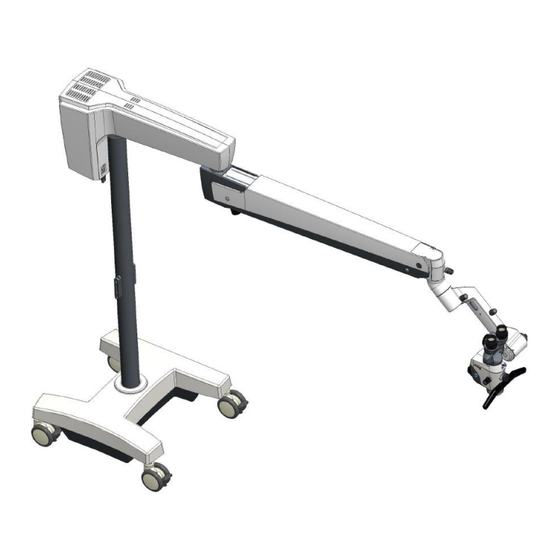
Stands and labels Instructions for Use Stands and labels Stands/mounts Floor stand Ceiling mount Wall mount 9 / 65 305935-9900-000–1.3 –2020-08-25-for USA... -
Page 10: Labels
Maximum load The maximum load on the suspension arm on suspension must not exceed 14 kg. Maximum weight The maximum weight of EXTARO 300 (floor stand) is 195 kg The input voltage at the power socket should Input voltage be compliant with the specification on this label. - Page 11 To avoid any ocular risk, do hazard not look directly at the light. May be harmful to the eyes. 1) Carl Zeiss Meditec Inc. is responsible for Distributor the distribution and complaint handling for information (for EXTARO 300 in the USA and Canada.
-
Page 12: Controls
Instructions for Use Controls Transport Always hold and push the column at the position indicated point for transportation. “Observe the This label tells the user to read the user Instructions for manual for detailed function of the control Use” label Controls Controls on the microscope Mode Control knob... -
Page 13: Controls On The Yoke And Stand
Controls Instructions for Use Pupillary distance adjustment Diopter setting on eyepiece Emergency Knob Securing screw Adjustment knob on external focus (optional) NOTE Loosening the securing screw may cause the tube to fall off! Controls on the yoke and stand • For the detailed definition of all the axes (Axis 1 ~ Axis 6) on the suspension system and yoke, please refer to Section 11.2. - Page 14 Instructions for Use Controls Brakes Brake of Axis 1 for locking the Brake of Axis 2 for locking Brake of Axis 3 for locking carrier arm the suspension arm the vertical position of suspension arm Brake of Axis 4 for locking Brake of Axis 5 for locking Brake of Axis 6 for locking yoke orientation...
- Page 15 Controls Instructions for Use On/Off Power on/off switch Connections (USB, HDMI, LAN, Power) Power inlet socket Strain relief device to prevent Video interface and Ethernet inadvertent cable unplugging connections 15 / 65 305935-9900-000–1.3 –2020-08-25-for USA...
-
Page 16: Description Of System Options
For details of the eyewear, please contact your authorized ZEISS partner. To further lower the risk of illumination light, EXTARO 300 also provides a function called SpotLight that allows the user to control the illuminated-field diameter via the Mode Control knob. -
Page 17: Augmented Visualization
Description of system options Instructions for Use Augmented visualization 5.2.1 Multispectral Mode The Multispectral Mode is used to enhance contrast between tissue and vasculature. Tissue image under white light Tissue image under Multispectral Mode 5.2.2 Green Color Mode The Green Color Mode is used to enhance contrast between blood and tissue. Tissue image under white light Tissue image under Green Color Mode 5.2.3 NoGlare Mode... -
Page 18: Documentation
Instructions for Use Description of system options Documentation Three optional solutions are available for EXTARO 300 in terms of image acquisition and video recording. 5.3.1 Essential Communication package Main features: • Integrated HD (1080p) camera • Video interface - HDMI output to monitor - USB port for image &... -
Page 19: Complete Communication
Trigger with the mode control knob on microscope or with remote control • Network interface (including wireless & wired Ethernet connection) • ZEISS Connect (iPad app) for - Camera control including smart recording - Chair side patient consultation - Media asset management - Essential adjusting of images and video The Connect app is available for download in the Apple app store. -
Page 20: External Camera Adapter (Photo Adapter)
Note that the user should also buy a third-party adapter to connect the camera with the photo adapter. Please refer to the product datasheet of EXTARO 300 or consult your authorized ZEISS partner for ordering information of the external camera adapter. -
Page 21: External Focus
Description of system options Instructions for Use External focus When used with a laser micromanipulator and locked Varioskop drive, the External Focus module allows manual fine focusing without changing the set focal planes of the OPMI and the laser micromanipulators. External Focus Laser micromanipulator adapter An optional laser micromanipulator adapter can be used for attaching a laser micromanipulator at the... -
Page 22: Asepsis & Drapes
5.7.1 Reusable asepsis sets For sterile use, the system can be equipped with asepsis rubber caps that can be sterilized in autoclaves. For EXTARO 300, the following new asepsis caps are now available for use: • Asepsis cap (M/N: 305935-8041-000) for Mode Control knob •... -
Page 23: Drapes
An optional iPad docking station can be used to dock, charge and lock the iPad on the backpack of the carrier arm. Please refer to the product datasheet of EXTARO 300 or consult your local dealer for ordering information of the iPad docking station. -
Page 24: Preparing System For Use
Instructions for Use Preparing system for use potentially damage that device or the EXTARO 300 system. Preparing system for use Relocating the system Turn off the device and Fold the system into a Unlock all casters. unplug the power cable. -
Page 25: Connecting The System
Preparing system for use Instructions for Use • Always hold the stand column at the position marked by the Transport Position Label (see Section 3.2). • Mind the maximum passage height when passing through doorways. Avoid collisions of any kind. •... -
Page 26: Balancing
Instructions for Use Preparing system for use • When setting up your system, make sure to comply with the requirements of IEC 60601-1:2005, chapter 16; in some countries IEC 60601-1- 1:2000 may still be valid. • Also comply with the Medical Device Operator Ordinance or other national codes. - Page 27 Preparing system for use Instructions for Use The yoke has two rotation axes to balance: the left- to-right tilt axis (Axis 5) and the front-to-back tilt axis (Axis 6), as illustrated in the left picture. Balance adjustment of the yoke is done using the knobs and cranks in a sequence as shown on the front label.
- Page 28 Instructions for Use Preparing system for use Slowly loosen Rotate the OPMI to align the ▶ moves up from when friction knob to unlock ▶ green arrow with the green OPMI is released, unfold and the axis. circle as close as possible, rotate the crank in the then slightly release the OPMI reverse direction such that...
- Page 29 Preparing system for use Instructions for Use ▶ moves below , rotate Slightly tighten the friction adjustment knob such that the big knob in the other OPMI keeps in balance within direction such that OPMI the desired working region ▶ becomes balanced when around the front-to-back tilt aligns with...
- Page 30 Instructions for Use Preparing system for use If ▲ moves to the right side of Slowly tighten the friction Fine-tune balance adjustment knob such that rotating the big knob to the circle , rotate the crank achieve equivalent balance Axis 5 is balanced within the in the other direction such effects on both left and right whole required region.
-
Page 31: Balancing The Suspension Arm
Preparing system for use Instructions for Use 6.3.2 Balancing the suspension arm Move the suspension arm into its Slightly lift the suspension arm from its horizontal position and tightly hold it horizontal position. Rotate the balance with one hand. Use the other hand to adjustment knob so that the suspension arm loosen the friction adjustment knob on can keep stationary at any height within its... -
Page 32: Preparing Sterility
6.4.1 Attaching asepsis caps For sterile use, the system can be equipped with resterilizable products. The asepsis sets available from ZEISS contain various caps that can be sterilized in autoclaves. CAUTION! Risk of infection caused by contaminated asepsis caps and drapes •... -
Page 33: Finding Ergonomic Working Position
A drape adapter is needed for attaching the drape on Varioskop 230. For details, please see Section 5.7.2. For detailed information on sterilization, please refer to the product datasheet of EXTARO 300 or consult your local authorized ZEISS partner. Finding ergonomic working position (1). -
Page 34: Adjusting Eyepieces
Instructions for Use Preparing system for use Adjusting eyepieces Rotate diopter setting ring to adjust Rotate eyecups to define a proper prescription according to the diopter position for resting the eye. scale. The eyepieces provide ametropia compensation between - 8 D and + 5 D. Eyeglass wearers who wear eyeglasses during their work set the diopter setting ring to the zero position. -
Page 35: Parfocal Imaging
Preparing system for use Instructions for Use Parfocal imaging Parfocal imaging means that the image will remain sharp under different magnifications once it gets focused under the maximum magnification. Setting the correct diopter of the eyepiece is critical to ensuring parfocal imaging. If you don’t know the diopter of your eyes and would not like to wear any corrective eyeglasses during operation, you can follow the procedure described below to properly adjust the diopter of the eyepieces. -
Page 36: Working With The Microscope
Instructions for Use Working with the microscope Working with the microscope Using the camera 7.1.1 Recording image/video with the Mode Control knob Capturing image Short click (t ≤ 0.8s) at the center of the Mode Control knob to capture an image. Recording video Long click (t>0.8s) at the center of the Mode Control knob to start video recording. -
Page 37: Adjusting White Balance Of Camera
Working with the microscope Instructions for Use 7.1.3 Adjusting white balance of camera White balance of the camera ensures that the color of its output image of an object under White Light Mode is close to the true color of the object as seen under normal daylight. Readjust the white balance of the camera if the color temperature of light source is changed. -
Page 38: Adjusting Light Intensity
Instructions for Use Working with the microscope Adjusting light intensity Rotate clockwise to increase Rotate counterclockwise to light intensity decrease light intensity On the front face of the OPMI, there are 5 white-colored LED indicators arranged in an arc above the Mode Control knob. These LEDs are designed to roughly indicate the set intensity level of the illumination under the corresponding mode. -
Page 39: Switching Between Augmented Visualization Modes
Working with the microscope Instructions for Use Switching between Augmented Visualization modes Short press (t<0.8s) the Mode Press the Mode Control Press the Mode Control knob Control knob upward knob rightward to activate leftward to activate Green activate NoGlare Mode. Multispectral Mode. -
Page 40: Cleaning And Disinfection
8.1.2 Prevention of fogging To protect the eyepiece optics from fogging, we recommend using an anti-fogging agent. Anti-fogging agents provided by eye care professionals for use with eyeglass lenses are also suitable for Zeiss eyepieces. Please observe the Instructions for Use supplied with each anti-fogging agent. -
Page 41: Disinfection
Cleaning and disinfection Instructions for Use Disinfection If the system surfaces need to be disinfected, please note the following: Risk of damaging the paint on the device! CAUTION! The use of unauthorized disinfectants can cause the paint on the device to become damaged. -
Page 42: Maintenance
The following table lists the relevant maintenance activities and shows at which maximum intervals they must be performed. All maintenance activities listed here require device-specific knowledge. Please contact your local ZEISS Service or an authorized partner for performing maintenance activities in due time. - Page 43 Maintenance Instructions for Use Every 12 months Component Procedure / Criteria Visual inspection: Documentation and identification labels Manuals and identification labels available, undamaged, complete and legible Carrier system Function test: including microscope − Play-free movement of bearings, stops and suspensions mount −...
-
Page 44: Safety Check
Instructions for Use Maintenance Safety check Risk of injury! WARNING! Cables and plug connections may come loose and parts of the housing may become live. The user and patient may suffer an electric shock. • To prevent any impairment of the system's safety as a result of aging, wear etc., the operating company must ensure, in accordance with the applicable national regulations, that the regular technical safety checks defined for this system are performed on schedule and to the... -
Page 45: Trouble Shooting
Trouble shooting Instructions for Use Trouble shooting Causes of malfunctions and remedies Fault Cause Rectification Power plug of stand not Plug in the power cord. No function at all inserted. Power switch of stand not Press power switch. switched on Automatic circuit breaker in Press power switch. -
Page 46: Failure Of The Mode Control Knob
Emergency knob (see Section 4.1) to return to normal white light mode (e.g. use a coin to rotate it), and then power on the system again. 3) Contact Zeiss Service. Failure of the motorized filter wheel (optional) In case the motor of the filter wheel assembly cannot move: 1) If user still wants to continue work with the OPMI before fixing the issue, he/she can use the Emergency knob (see Section 4.1) to rotate the filter wheel (e.g. -
Page 47: Technical Specification
Technical specification Instructions for Use Technical specification Electrical data Designation Value Only connect the device to wall outlets which are equipped Power connection with a properly connected protective ground conductor. 100VAC – 240 VAC Rated voltage 50Hz/60Hz Power consumption Max. 120 VA 1) Power input:... -
Page 48: Mechanical Data
Length: 1000 mm (axis to axis) Suspension arm Swivel angle (Axis 2): ±150° Vertical lift:± 400 mm Length: 500 mm (axis to axis) Swivel angle: EXTARO 300 (floor stand):±360° Carrier arm EXTARO 300 (wall mount):±97° EXTARO 300 (ceiling mount):±163° Yoke Angled (135°) yoke... -
Page 49: Definition Of Axis 1~Axis 6
Technical specification Instructions for Use OPMI with floor stand approx. 195 kg (with all accessories). Total weight of OPMI EXTARO 300 OPMI with floor stand approx. 420 kg (including wooden transportation box). 11.2.3 Definition of Axis 1~Axis 6 Axis 1... -
Page 50: System Dimensions
Instructions for Use Technical specification 11.2.4 System dimensions ±400mm Floor stand Wall mount ±400mm 50 / 65 305935-9900-000–1.3 – 2020-08-25-for USA... - Page 51 Technical specification Instructions for Use Ceiling mount ±400mm 51 / 65 305935-9900-000–1.3 –2020-08-25-for USA...
-
Page 52: Optics Data
Instructions for Use Technical specification Optics data Designation Value 5-step apochromatic magnification changer, manual adjustment. Magnification factors: γ = 0.4x, γ = 0.6x, γ = 1.0x, γ = 1.6x, γ = 2.5x Magnification Total magnification (12.5x eyepiece): • 3.0x ~ 19.0x at a working distance of 200 mm •... -
Page 53: Documentation Package
Technical specification Instructions for Use Documentation package Essential Communication Complete Communication 1 chip 1/3 inch progressive scan 1 chip 1/3 inch progressive scan Image sensor Color CMOS Sensor Color CMOS Sensor 1920 (H) x 1080 (V) 1920 (H) x 1080 (V) Active pixels (Pixel size: 2.8 μm x 2.8 μm) (Pixel size: 2.8 μm x 2.8 μm) -
Page 54: Ambient Requirements For Operation
Instructions for Use Technical specification Ambient requirements for operation Designation Value Temperature + 10°C ... + 40°C Rel. humidity 30% ... 75% Air pressure 700 hPa ... 1060 hPa Ambient requirements for transport and storage Designation Value Temperature - 40°C ... + 70°C Rel. -
Page 55: Wireless Communication
Technical specification Instructions for Use Wireless communication 11.7.1 Wi-Fi router information • Release version of firmware: V1.2 • Frequency band(s): 2.4G:2.412 – 2.472 GHz • RF Output Power: ▪ 802.11b: 19.75 dBm (EIRP) ▪ 802.11g: 19.85 dBm (EIRP) ▪ 802.11n 20MHz: 19.95 dBm (EIRP) ▪... -
Page 56: Guidelines And Manufacturer's Declaration For Electromagnetic Compatibility
External AC Power Cable Cable length: 5m The following essential performances of EXTARO 300 can still be retained even at the presence of the electromagnetic disturbances mentioned in subsequent sections: - The light source can offer illumination of specified brightness without flashing and the light intensity can be adjusted normally. -
Page 57: Electromagnetic Emission
11.8.1 Electromagnetic emission The EXTARO 300 is intended for operation in an electromagnetic environment as specified below. The customer or the user of EXTARO 300 is responsible for ensuring that the device is operated in such an environment. Emission test... - Page 58 ; 0.5 T (0°, environment. If the user of Voltage dips, short 45°, 90°, 135°, 180°, 45°, 90°, 135°, 180°, EXTARO 300 requires 225°, 270° and 315°) 225°, 270° and 315°) interruptions and continued function even in the voltage variations as...
-
Page 59: Electromagnetic Immunity For Non-Life-Supporting Me Equipment And Me Systems
11.8.3 Electromagnetic immunity for non-life-supporting ME equipment and ME systems The device EXTARO 300 is intended to be operated in one of the electromagnetic environments specified below. The customer or the user of the device EXTARO 300 is responsible for ensuring that it is operated in such an environment. -
Page 60: Recommended Safety Distances Between Portable And Mobile Rf Communication Equipment And The Extaro 300
11.8.4 Recommended safety distances between portable and mobile RF communication equipment and the EXTARO 300 The device EXTARO 300 is intended for use in an electromagnetic environment in which RF disturbances are controlled. The customer or the user of the device EXTARO 300 can help prevent electromagnetic... -
Page 61: Ordering Data
Technical specification Instructions for Use Ordering data Only operate the system with the accessories included in the delivery package and proved by ZEISS. You will find the contact responsible for orders in your country on this website: www.zeiss.com/meditec The product configurations, accessories and spare part that are applicable for authorized ZEISS partners are stipulated by contract. -
Page 62: Simplified Eu Declaration Of Conformity
Simplified EU declaration of conformity Simplified EU declaration of conformity Hereby, Carl Zeiss Suzhou Co., Ltd., declares that the radio equipment type EXTARO 300 is in compliance with Directive 2014/53/EU. The full text of the EU declaration of conformity is available at the following internet address: www.zeiss.com/meditec. -
Page 63: Disposal
Disposal Instructions for Use Disposal NOTE Incorrect disposal A high proportion of electronic scrap at the unsorted municipal waste facility poses arisk to the environment. • Do not dispose of the waste as normal municipal waste. • Observe the local laws/regulations governing the disposal of electrical and electronic equipment. -
Page 64: List Of Abbreviations Term
Instructions for Use List of abbreviations term List of abbreviations term Term Explanation Camera Control Unit Communauté Européenne (European Community) Canadian Standards Association (a non-governmental organization that test and certifies product safety) Electromagnetic Compatibility Define non-interference of electrical and electronic devices with their environment EIRP Effective Isotropic Radiated Power... - Page 65 EC | REP Carl Zeiss Meditec AG Carl Zeiss Suzhou Co., Ltd Modern Industrial Square 3-B, Goeschwitzer Strasse 51-21 No.333 Xingpu Road 07745 Jena Suzhou Industrial Park, Suzhou Phone : +49 36 41 22 03 33 China 215126 Fax :...
Need help?
Do you have a question about the EXTARO 300 and is the answer not in the manual?
Questions and answers