Table of Contents
Advertisement
Advertisement
Chapters
Table of Contents

Related Manuals for Festo CECX-X-C1 Series


Summary of Contents for Festo CECX-X-C1 Series
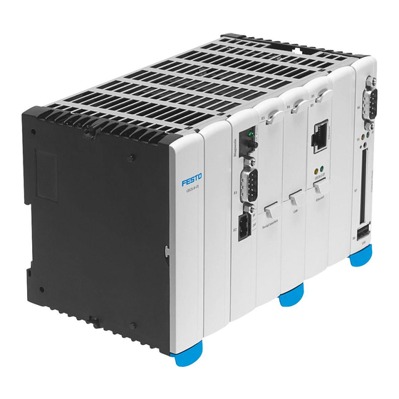
- Page 1 Manual Controller Modular CECX CECX-X-C1 CECX-X-M1 761886 1112c en...
- Page 2 1112c en...
- Page 3 Edition ..... . Rev 01 (1112c en) Designation ....GDCC-CECX-SY-EN © (Festo AG & Co. KG, D-73726 Esslingen, 2011) Internet: http://www.festo.com E−Mail: service_international@festo.com...
- Page 5 Content CECX-I: CECX modular control system:: Overview of functions Network configuration Control configuration CECX-II: System ManualCECX CECX-III: Library: Ethernet.lib CECX-IV: Library: EventData.lib CECX-V: Library: IncEnc.lib CECX-VI: Library: Festo_EasyIP.lib CECX-VII: Library: PLCService.lib CECX-VIII: Library: SysLibComEx.lib CECX-IX: Library: Festo_Motion.lib CECX-X: Library: Festo_PartDetector.lib CECX-XI: Interface FED/VipWin 1112c en...
- Page 6 1112c en...
- Page 7 CECX modular control system CECX modular control system...
-
Page 8: Table Of Contents
CECX modular control system Table of contents CECX modular control system ........................1 Overview of functions and libraries ......................1 Network configuration..........................12 Network Configuration[SLOT] ......................12 Control configuration ..........................13 Adding / configuring a module ......................13 End points and status values of configured modules ................14 Process map............................ -
Page 9: Cecx Modular Control System
The development environment therefore contains many functions that are only available on specific controls. Not all these functions are supported by the CECX modular control system. The functions of CoDeSys provided by Festo that are supported by CECX modular control system is contained in the Overview of functions further down. - Page 10 CECX modular control system Actions shade programs Compiling LREAL as REAL Number of data segments Excluding objects Compiler version Yes 2) Macro before compiling Macro after compiling Automatic check Passwords Source download Only source code All files Implicit during loading Notes during loading Creating implicit during boot project...
- Page 11 CECX modular control system Functionality / functions Supported General online functions Login (part 1) Logout Loading Start Stop Reset Reset (cold) Reset (origin) Breakpoint on/off Breakpoint dialog Single step over Single step in Single cycle Writing values Forcing values Cancel forcing Writing/forcing dialog Functionality / functions Supported...
- Page 12 CECX modular control system 1) If a project is stored in the control (project options->source download) the name "Source.dat" is always allocated on the target system. To open the project that has been stored in the control in CoDeSys it must first be uploaded (online->load file from control, specify "Source.dat"...
- Page 13 CECX modular control system Functionality / functions Supported Task configuration Insert/add task Name Priority (0-31) Yes 1) Cyclical Free-running Event-driven Externally event-driven Watchdog Time Sensitivity Insert/add program call-up 1) Longer waiting decides at equal priority Functionality / functions Supported System events 1) start stop before_reset...
- Page 14 CECX modular control system Defining Extras->Debug task Switching Extras->Debug task on/off Extras-> call hierarchy 1) The control is a preemptive multi-task system in which the tasks with the higher priority can interrupt or displace those with a lower one. The system events are executed in a highest priority task context and therefore displace all other tasks.
- Page 15 CECX modular control system Functionality / functions Setting Target system settings Memory partitioning Basis, area Fixed setting Size (code) 6 MB Size per segment (global) 14 MB Size (marker) 8 KB Size (input) 8 KB Size (output) 8 KB Size retain 128 KB 1) Own retain segment on/off Size of the entire data memory...
- Page 16 CECX modular control system Initializing Inputs Yes / fixed Automatically loading boot project Yes / can be Softmotion Yes / can be Maintain forcing No / fixed Save Cycle-independent forcing Functionality / functions Supported Target system settings Network Supporting parameter manager Yes / can be functions Supporting network variables...
- Page 17 CECX modular control system 1) Network variables are only supported via UDP. 2) MS-DOS file name conventions (8+3 characters). Functionality / functions Supported Trace recording All functions PLC browser All functions Parameter manager All functions All functions IEC operators and Arithmetic operators additional standard Bit string operators...
- Page 18 All functions external applications SoftMotion All functions Yes 2) 1) Not contained in the scope of supply of CoDeSys provided by Festo. 2) Target-dependent Libraries on CECx CoDeSys provided by Festo makes available the following libraries for the CECx: Library...
- Page 19 CECX modular control system Standard.lib Modules that are required by IEC61131-3 as From 3S: − standard standard modules for an IEC programming libraries on CoDeSys system. − Modbus libraries on Util.lib Modules for BCD conversion, bit/byte CoDeSys functions, mathematical help functions, controllers, signal generators, function manipulators and analog value processing AnalyzationNew.lib...
-
Page 20: Network Configuration
CECX modular control system ModbusTCPSrv.lib Modules for ModuBus TCP-Server 3S additional libraries 1) The SysLibCallback.lib supports the system events listed under "System events". 2) Example for accessing a USB stick: sFileName '/usbmassstorage.0.0/testdatei.txt'; dwFilePointer SysFileOpen(sFileName, 'a'); 3) SysRtcCheckBattery and SysRtcGetHourMode are not supported. When a date is set before 1990-12- 27-00:00:00 with function SysRtcSetTime, this is lost after a system restart. -
Page 21: Control Configuration
CECX modular control system from the DHCP server. Answer on find requests When selected: the control answers to search requests. See Search Network and Add PLC. Synchronize RTC with PC When selected: After confirmation with OK the selected control takes over the date and time from the PC. Reboot on OK When selected: A reboot is carried out after OK, to take over the settings. -
Page 22: End Points And Status Values Of Configured Modules
CECX modular control system In both cases a module is added by clicking on ExtModules[SLOT] with the right mouse button, selecting Add subelement and clicking on the desired module in the menu offered. The parameters that can be configured are listed in tab Module parameters. See also online Help of the CoDeSys programming system, Resources, chapter Export/import of modules. -
Page 23: Process Map
CECX modular control system For a description of the stored status values: See the description of the configuration of modules in the following chapters. Process map Input Input physikalische Treiber Inputs (Sensoren) Output Output physikalische Treiber Outputs (Aktoren) Merker Byte addressing is used. %IX0.0 %IX1.0 %IX2.0... - Page 24 CECX modular control system The "auto" setting and the specific assignment of addresses should not be mixed in an control system. CECX-D-16E Digital input module 16 digital inputs of type 1 Module parameters Name Value Description Address Auto The address set on the hex switch on the module is recognized and taken over automatically.
-
Page 25: Address Setting For Modules
CECX modular control system Possible error states (when status = TRUE) Module status: module is defective or missing. DI status: no error message CECX-D-14A-2 Digital output module 14 digital output modules 2A at 50% coincidence, divided into 2 groups (6 and 8 outputs), short-circuit protected, overload protection, short-circuit detection, group cut-off. -
Page 26: Cecx-D-8E8A-Np-2
CECX modular control system affected by the short circuit. Status values as diagnosis information The following status values are created for this module (example): Possible error states (when status = TRUE) Module status: module is defective or missing. DO status: Short circuit of the outputs. - Page 27 CECX modular control system scan The short-circuit detection reactivates the outputs not affected by the short circuit. DI0 - DI7: despike None No input signal debouncing. 100 ms Debouncing time 100 ms. DI0 - DI1: Interrupt None No edge evaluation. Rising Signal change at rising edge.
-
Page 28: Cecx-D-6E8A-Pn-2
CECX modular control system CECX-D-6E8A-PN-2 Digital input/output module 6 digital inputs source, of which 2 are interruptible 8 digital outputs 2A sink at 50% coincidence, short-circuit protected, overload protection, short-circuit detection, group cut-off Module parameters Name Value Description Address Auto The address set on the hex switch on the module is... -
Page 29: Cecx-A-4E-V
CECX modular control system Status values as diagnosis information The following status values are created for this module (example): Possible error states (when status = TRUE) Module status: module is defective or missing. DI status: no error message DO status: short circuit of the outputs. -
Page 30: Cecx-A-4A-V
CECX modular control system 0..URef Single-ended input circuit, calibration standardized to URef. Status values as diagnosis information The following status values are created for this module (example): Possible error states (when status = TRUE) Module status: module is defective or missing. AI status: sensor failure detection CECX-A-4A-V... -
Page 31: Cecx-A-4E4A-V
CECX modular control system Status values as diagnosis information The following status values are created for this module (example): Possible error states (when status = TRUE) Module status: module is defective or missing. AO status: no error message CECX-A-4E4A-V Analog input/output module ... -
Page 32: Cecx-A-4E4A-A
CECX modular control system Possible error states (when status = TRUE) Module status: module is defective or missing. AI status: sensor failure detection AO status: no error message CECX-A-4E4A-A Analog input/output module 4 analog inputs 0-20mA/4-20mA, resolution: 14 4 analog outputs 0-20mA/4-20mA, resolution: 12 Bit Module parameters... -
Page 33: Cecx-E-4E-T-P1
CECX modular control system Possible error states (when status = TRUE) Module status: module is defective or missing. AI status: sensor failure detection at 4...20 mA AO status: no error message CECX-E-4E-T-P1 Temperature measurement module 4 temperature inputs for PT 100 temperature sensor ... -
Page 34: Cecx-E-6E-T-P2
548-1 (-100 °C to 1000 °C). For thermocouple type L (Fe-CuNi) according to DIN 43710/1977 (-100 °C to +700 °C). *) See online help section titled Target system - Festo CECX (hardware configuring,module CECX-E-6E-T- P2, chapter Functional description). Status values as diagnosis information... -
Page 35: Cecx-F-Pb-S-V1 (12 Bytes, 32 Bytes, 64 Bytes)
CECX modular control system The following status values are created for this module (example): Possible error states (when status = TRUE) Module status: module is defective or missing. TI status: sensor failure detection CECX-F-PB-S-V1 (12 Bytes, 32 Bytes, 64 Bytes) PROFIBUS Slave interface module ... -
Page 36: Cecx-F-Pb-V1
CECX modular control system You can find more detailed information in the specification of the protocol PROFIBUS-DP (Decentralized Peripherals) in the relevant field bus literature. Status values as diagnosis information The following status values are created for this module (example for 32-byte module): Possible error states (when status = TRUE) Module status: module is defective or missing. - Page 37 CECX modular control system by selecting CECX-F-PB-V1. For the use of Profibus DP-V1 services, set the module parameter DPV1Support of the appropriate slave to "Enabled". Please consider, that the behaviour of not all Profibus DP-V1-slaves conforms with the standard. If the DP-V1 communication does not work with the "Enabled" setting, set it to "Disabled".
-
Page 38: Cecx-C-2G2
CECX modular control system CECX-C-2G2 Motion extension module Incremental encoder (500 kHz)) 2 channels Module parameters Name Value Description Address Auto The address set on the hex switch on the module is recognized and taken over automatically. See chapter "Address setting for modules". -
Page 39: Cecx-S-2S1
Status values as diagnosis information The following status values are created for this module (example): Possible error states (when status = TRUE) Module status: module is defective or missing. Additional information: See online help section titled Target system - Festo CECX (CECX-S-2S1). CECX-I 31... -
Page 40: Cecx-C-2G1
CECX modular control system CECX-C-2G1 Serial interface module SSI Interface 4 interfaces Modul parameters Name Value Description address auto The address set on the hex switch on the module is recognized and taken over automatically. See chapter "Address setting for modules". 0 - F The address set here (specified in hexcode) must be brought into agreement with the position of the address... -
Page 41: Cecx-C-S1, Cecx-S-S4
CECX modular control system CECX-C-S1, CECX-S-S4 Serial option module: CECX-C-S1: RS-232-C, CECX-S-S4: RS-485/422 Modul parameters These modules are configured as CoDeSys interface in the PLC configuration via Communication Parameters, SIO Config. For the application, these interfaces are useable via the functions from the CoDeSys SysLib Com. - Page 42 CECX modular control system CAN module selection Select the add-on modules of the bus link module via CAN-module selection. At the bus the CECX-B-CO sorts the modules in the following sequence: 1. CECX-E-6E-T-P2 2. CECX-A-4E4A-V 3. CECX-A-4E4A-A 4. CECX-A-4E-V 5. CECX-A-4A-V 6.
-
Page 43: Can Master [Slot]
CECX modular control system The system configuration will be added with an entry. If the message appears "Caution! The following PDOs are currently not active: ...", it can be ignored. These are PDOs, which are created but not used in the system. In the system configuration any name can be entered for the created system variable (e.g. -
Page 44: Bus Interface [Slot] (For Controller Cecx-X-M1)
CECX modular control system END_IF Attention: This flag must not be set cyclically, since the individual nodes ca no longer be started after a failure. Application example for usage of library „BusDiag_Lib“: Declaration of variables: PROGRAM BusDiag_Lib_CAN DiagGBS : DiagGetBusState; DiagGS : DiagGetState;... -
Page 45: Unused [Slot]
CECX modular control system Information on application The cycle time for the motion task is configured depending on the used drives. If you use CMMS-AS, CMMS-ST, SFC-LAC oder SFC-LACI the minimal cycle time is 8 ms. For more information see the systemdescription of the drives. Unused [SLOT] Not used at the moment. - Page 46 CECX modular control system CECX-I 38...
- Page 47 System manual CECX...
- Page 48 CECX-II...
- Page 49 Content System Manual CECX Product design ........................1-1 Introduction ........................1-1 Purpose of the document..................1-1 Target groups, preconditions ................1-1 Intended use of the CECX modular control system ..........1-2 Notes on this document ..................1-3 General product-specific terms and abbreviation ..........1-3 Application and registrations................1-4 Safety notes ........................2-1 Representation ....................2-1 General safety instructions .................2-2...
- Page 50 Content System Manual CECX Switch-on control ....................7-4 Creating a CoDeSys project ................7-4 Establishing the connection to the PC/control ............7-5 Configuring modules..................7-15 Connecting an FED ..................7-16 First programming steps ...................7-20 Operating behavior ......................8-1 Button and display, general information .............8-1 Start-up .......................8-2 Operating states ....................8-3 Diagnosis ........................9-1 Display of errors in the 7-segment display............9-1...
- Page 51 Content System Manual CECX 15.1 Introduction .......................15-1 15.2 Safety notes......................15-1 15.3 Description of the module .................15-3 15.4 Connections and wiring ..................15-4 15.5 Configuration ....................15-9 15.6 Operating behavior ..................15-11 15.7 Disposal ......................15-11 15.8 Technical data ....................15-12 15.9 EC directives and standards................15-13 16 Digital output module CECX-D-14A-2...............16-1 16.1 Introduction .......................16-1...
- Page 52 Content System Manual CECX 19.7 Disposal ......................19-12 19.8 Technical data ....................19-13 19.9 EC directives and standards................19-15 20 Analog output module CECX-A-4A-V ...............20-1 20.1 Introduction .......................20-1 20.2 Safety notes......................20-1 20.3 Description of the module .................20-3 20.4 Connections and wiring ..................20-5 20.5 Configuration ....................20-8 20.6 Operating behavior ...................20-9...
- Page 53 Content System Manual CECX 24.1 Introduction .......................24-1 24.2 Safety notes......................24-1 24.3 Description of the module .................24-3 24.4 Connections and wiring ..................24-5 24.5 Configuration ....................24-9 24.6 Functional description..................24-10 24.7 Operating behavior ..................24-13 24.8 Disposal ......................24-13 24.9 Technical data ....................24-14 24.10 EC directives and standards................24-16 25 PROFIBUS Master interface module CECX-F-PB-V1 ..........25-1 25.1 Introduction .......................25-1...
- Page 54 Content System Manual CECX 28.3 Description of the module .................28-3 28.4 Operating elements and displays ..............28-4 28.5 Connections and wiring ..................28-5 28.6 Configuration ....................28-7 28.7 Disposal ......................28-8 28.8 Technical data ....................28-9 28.9 EC directives and standards................28-10 29 SSI Interface module CECX-C-2G1 ................29-1 29.1 Introduction .......................29-1 29.2...
- Page 55 Content System Manual CECX 32.6 EMC and wiring guidelines ................32-10 32.7 Operating behavior ..................32-11 32.8 Disposal ......................32-11 32.9 Technical data ....................32-12 32.10 EC directives and standards................32-13 33 Ethernet option module CECX-C-ET ................33-1 33.1 Introduction .......................33-1 33.2 Safety notes......................33-1 33.3 Description of the module .................33-3 33.4 Installation instructions ..................33-4 33.5...
- Page 56 Content System Manual CECX VIII...
-
Page 57: Product Design
System manual CECX / Product design Product design The unit is available in the following designs: Product design Description CONTROLLER Modular controller CECX CECX-X-C1 Software: CoDeSys CONTROLLER Modular controller CECX CECX-X-M1 Software: CoDesys with SoftMotion In the following the unit is described as CECX modular control system or simply as control. CECX-II 0-1... - Page 58 System manual CECX / Product design CECX-II 0-2...
-
Page 59: Introduction
System manual CECX / Introduction 1 Introduction Purpose of the document This document describes the structure of the CECX modular control sys- tem. It further describes the assembly and installation, the wiring, the operation and displays of the modules. The installation and configuration is described to the extent that the user has a CECX modular control system that is ready for operation. -
Page 60: Intended Use Of The Cecx Modular Control System
System manual CECX / Introduction Target group Prerequisite knowledge and ability Service technician Technical basic education (vocational high school, engineering degree or corresponding professional experience), Knowledge in: working mode of a PLC, safety instructions, working mode of machine or plant, ... -
Page 61: Notes On This Document
System manual CECX / Introduction Notes on this document Information If necessary, also adhere to the documentation accompanying the mod- ules. 1.4.1 Contents of the document System overview Start-up description Operating behavior Diagnosis EMC and wiring guidelines ... -
Page 62: Application And Registrations
System manual CECX / Introduction Term/abbreviation Significance PROFIBUS PROcess Field BUS; process and field bus standard which has been defined in IEC 61158 Type 3. PROFIBUS address Serves for the clear identification of a bus participant in the PROFIBUS Project engineering Project engineering manuals are those documents that provide the manual machine and plant project engineer with the necessary information... -
Page 63: Safety Notes
System manual CECX / Safety notes 2 Safety notes Representation At various points in this manual you will see notes and precautionary warn- ings regarding possible hazards. The symbols used have the following meaning: DANGER! indicates an imminently hazardous situation which will result in death or serious bodily injury if the corresponding precautions are not taken. -
Page 64: General Safety Instructions
System manual CECX / Safety notes General safety instructions The documentation contains information necessary for planning the use of the CECX hardware. Familiarity with and correct application of the information contained in these manuals is a prerequisite for successful planning and safe installation, commissioning and maintenance of automation systems. - Page 65 System manual CECX / Safety notes ATTENTION! Fire danger for component failure! Ensure adequate fuse protection of the 24 V DC power supply of the CECX modular control system in the end usage! The max. permitted fuse is 10A! ...
-
Page 66: Safety Instructions For Programming
System manual CECX / Safety notes WARNING! All parts of the system that must be supplied with a voltage higher than safety extra-low voltage (SELV according to EN 61131-2) and has touchable metal parts, must be earthed. Otherwise, the series con- nected protection devices are ineffective. -
Page 67: Safety Instructions For Maintenance Work
ATTENTION! The device may only be opened by qualified personnel and only main- tenance activities expressly approved by Festo may be performed (see chapter “Service notes”). Any other manipulations to the device will result in loss of warranty. Requirement for UL508 and use conforming to EN 61131 The modules of the CECX modular control system are defined as "open... - Page 68 System manual CECX / Safety notes CECX-II 2-6...
-
Page 69: System Overview
System manual CECX / System overview 3 System overview Structure of the modular control The CECX modular control system is based on a modular concept and can be structured according to specific functional requirements. It consists es- sentially of a selection of CPU modules, I/O modules and operating and display units. - Page 70 System manual CECX / System overview 3.1.1 Structure of field bus systems Field bus systems can be assembled by means of plug-in option modules or add-on field bus modules. This enables communication with remote de- vices (filed bus slaves) and control systems. The installation of different op- tion modules in the CECX modular control system makes coupling or a ga- teway function possible.
- Page 71 3.1.2.2 Linking of Front End Displays (FED) Festo front end displays can communicate with the CECX modular control system via a serial connection or an Ethernet connection. The scope of supply from the designer of the FED includes appropriate drivers which support the easy variable exchange on the basis of the sym- bol files (see also online Help of CoDeSys).
-
Page 72: Working Mode Of The Control
System manual CECX / System overview Working mode of the control 3.2.1 Program processing The control operates according to the following principle: “Reading Inputs, Processing, writing Outputs”. The CECX modular control system carries out the following tasks during processing of each task defined with CoDeSys: Reading inputs: ... -
Page 73: Start-Up And Programming (Overview)
System manual CECX / System overview 3.2.3 Internal memory of the CECX modular control system The available memory of the CECX modular control system is divided au- tomatically under CoDeSys. Please adhere to the following maximum sizes: Memory Description Value Code Working memory to execute the user 6,144 KByte... - Page 74 System manual CECX / System overview 3.3.1 Programming languages CoDeSys offers all 5 programming languages standardized in EN 61131-3. There are two textual and three graphic programming languages. Each of these languages has specific characteristics that are ideally suited for car- rying out specific tasks.
- Page 75 System manual CECX / System overview 3.3.3 Specific target system online Help The specific target system online Help for the CECX modular control sys- tem is displayed only when the CECX modular control system has been set as target system. Access to the Help is gained via the online Help table of contents under "Target system".
- Page 76 System manual CECX / System overview CECX-II 3-8...
-
Page 77: General Assembly And Installation Instructions
System manual CECX / General assembly and installation instructions 4 General assembly and installation instructions General instructions on assembly and removal CAUTION Improper handling can damage the modules, option modules and the control sys- tem. Switch off the operating and on-load power supply before carrying out assembly, installation or maintenance work. -
Page 78: Footprint
System manual CECX / General assembly and installation instructions Footprint TS 35x7,5 +24V +24V AGND AGND 22,5 Mounting sketch To ensure air circulation, a free space of at least 30 mm must be main- tained over and underneath the modules. Adding modules Up to 12 modules (I/O, technology or field bus modules) can be lined up next to each other in any order on the right side of the CPU module. -
Page 79: Mounting/Dismounting The Boards And Modules
System manual CECX / General assembly and installation instructions Apart from the following exceptions up to 12 modules of the same kind can be placed in line on a CPU module or on a bus link module allowing for the power consumption and the bus load. - Page 80 System manual CECX / General assembly and installation instructions Plug together the modules with the CPU module to form one control block. The CPU module must be positioned to the extreme left, the add-on modules are added on to the right..
- Page 81 System manual CECX / General assembly and installation instructions Information When adding extension modules to a CPU module or to an existing group of add-on modules ensure that the locking pins are properly engaged. Furthermore, ensure that the entire package (CPU module and add-on modules) is secured on either side with the end clamps to prevent it from being displaced and to protect it against vibration.
- Page 82 System manual CECX / General assembly and installation instructions Removing the CECX modular control system CAUTION Risk of damaging components during installation work under voltage. Therefore, switch off the power supply and remove all cable connec- tions prior to starting dismantling work. This is how the CECX modular control system is removed from the mount- ing rail: Turn off power supply...
-
Page 83: Air Conditioning, Ventilation
System manual CECX / General assembly and installation instructions Air conditioning, ventilation Ventilation holes for dissipating the heat are placed at the top and under- side of the module. If the permissible ambient temperature is not exceeded, no external fan will be needed. Make sure that the ventilation holes are not covered. - Page 84 System manual CECX / General assembly and installation instructions CECX-II 4-8...
-
Page 85: Power Supply Of Modules
System manual CECX / Power supply of modules 5 Power supply of modules Connection The modules are supplied with voltage via the K-Bus plug. For a module formation with a CPU module this is done via the bus supply of the module row. -
Page 86: Power Consumption Of Modules
The power consumption of the modules available for the CECX modular control system is contained in the following table: Festo description Festo Power Power part number... -
Page 87: Example Power Calculation
System manual CECX / Power supply of modules Example power calculation Calculation of the power input required for the following instrumentation. UREF +24V ETHERNET CAN1 +24V Power supply of control Pxxxxx-xxxxx Pxxxxx-xxxxx Pxxxxx-xxxxx 5.3.1 Calculation of the load The following table lists the power required from the CPU module (called CPU for short in the following) for the option modules and the add-on mod- ules. - Page 88 System manual CECX / Power supply of modules Power requirement of loads = Number of outputs * capacity * coincidence factor, e.g. for 14 x 2 A - outputs: 14 * 2 A * 24 V * 0.5 = 336 W. Total power requirement for the power supply unit: 20 + 336 = 356 W.
-
Page 89: Operation And Displays
System manual CECX / Operation and displays 6 Operation and displays Setting the module address The modules in the system are addressed by means of a 16-position ad- dress switch. This enables all modules within a control package (consisting of CPU module and a maximum of 12 add-on modules) to be differentiated. The address switch is located on the side of the modules, underneath the K-Bus plug. -
Page 90: Diagnosis Display (Diagnostics)
The Compact Flash Card cannot be used as removable medium since it al- so has system programs stored on it. The Compact Flash Cards supported by the CECX modular control system can be requested and ordered from FESTO. CAUTION The Compact Flash Card can sustain damage if handled incorrectly! ... - Page 91 System manual CECX / Operation and displays ..LED 2..Eject key ..Slot Position of the slot and the operating elements CECX-II 6-3...
- Page 92 System manual CECX / Operation and displays Inserting the memory card How to slot in a Compact Flash Card: Turn off the power supply. Carefully slot in the Compact Flash Card with slight pressure in the di- rection of the arrow until it engages. Removing the memory card Turn off the power supply.
-
Page 93: Commissioning Of Codesys And Control
Install Target must be available on the PC. To install the TSP proceed as follows: Execute Install Target (Start -> Programs -> FESTO Software -> CoDeSys V2.3 by Festo -> Install Target). Window Install Target is displayed:... - Page 94 On the left under Possible target systems select Festo AG u. Co. KG and Click on Install. If necessary, you may have to confirm the creation of an installation directory. Festo AG u. Co. KG will then be displayed on the right under Installed tar- get systems. CECX-II 7-2...
- Page 95 System manual CECX / Commissioning of CoDeSys and control InstallTarget window with installed target system Click on Close. The files of the target Support Package are now installed. CECX-II 7-3...
-
Page 96: Switch-On Control
Start the CoDeSys by clicking on the CoDeSys icon on the desktop or with the command Start -> Programs -> Festo Software -> CoDe- Sys V2.3 by Festo -> CoDeSys V2.3 or via a shortcut on the desk- top. Creat a new Codesys project via File -> New and select the Festo control in the Configuration field. -
Page 97: Establishing The Connection To The Pc/Control
System manual CECX / Commissioning of CoDeSys and control Switch on the control as described above. Establishing the connection to the PC/control There are two options for establishing a connection between the PC and the control: TCP/IP connection via Ethernet and ... - Page 98 System manual CECX / Commissioning of CoDeSys and control Select the control under the Find PLC tab and press Config. The Communication parameters window opens for entering the network settings. After here, the network configuration only differs slightly depending on the obtainment of the IP address.
- Page 99 System manual CECX / Commissioning of CoDeSys and control 7.5.1.2 IP address fixed assignment In the IP config tab, locate the parameter for entering in the network setting. If the control has already been entered as active PLC, the network parame- ters in IP config can no longer be modified (Communication [Slot] - Set as active PLC).
- Page 100 System manual CECX / Commissioning of CoDeSys and control 7.5.1.3 Entering a new control Via connections over the network, you can add new controls from the net- work in the control configuration. Click on Communication[SLOT] in the navigation tree of the Control configuration window.
- Page 101 System manual CECX / Commissioning of CoDeSys and control Example: Development PC and control in the same network. IP addr. 192.168.181.1 subnet m. 255.255.255.0 IP addr. 192.168.181.3 subnet m. 255.255.255.0 hub / switch IP addr. 192.168.181.4 IP addr. 192.168.181.2 subnet m. 255.255.255.0 subnet m.
- Page 102 System manual CECX / Commissioning of CoDeSys and control Example: Separate network for development PCs and controls. hub / switch Gateway IP addr. 172.25.0.1 subnet m. 255.255.0.0 IP addr. 172.25.10.10 subnet m. 255.255.0.0 hub / switch gateway 172.25.0.1 IP addr. 172.25.10.11 subnet m.
- Page 103 System manual CECX / Commissioning of CoDeSys and control MAC-ID is the fixed address that clearly identifies an Ethernet device (Me- dia Access Control). IP address An IP address according to the standard IPv4 is generally specified with 4 decimal numbers divided by points (each 1 byte). Example for an IP address: 192.168.181.1 Both a network and an individual participant are allocated an IP address in the network.
- Page 104 System manual CECX / Commissioning of CoDeSys and control Information on the addresses of your in-house network is available from the network administrator. Setting the IP address The settings for IP addressing can be manually configured for each termi- nal unit. In large networks this is done centrally and automatically by means of DHCP (Dynamic Host Configuration Protocol).
- Page 105 System manual CECX / Commissioning of CoDeSys and control "Communication parameters" dialog Under Port, select that serial interface to your PC that was connected with the control. The standard values must be used for the remaining parameters (see graphic) or those values that were configured for this (see chapter "Configuration of the serial connection settings").
- Page 106 System manual CECX / Commissioning of CoDeSys and control Example dialog "serial connection settings" The following parameters can be entered in SIO Config: Parameter Description Port: Specification of the serial interface at the control, with which the connection to the PC is established. COM1 is the first interface of a plugged-in serial option module.
-
Page 107: Configuring Modules
System manual CECX / Commissioning of CoDeSys and control Configuring modules With the configuration the interconnection of the modules carried out during installation of the hardware is replicated in CoDeSys. At the bottom left select tab Resources Double click on Control configuration With the right mouse button click on ExtModules(SLOT) and attach the modules required for your project one after the other via Attach subelement. -
Page 108: Connecting An Fed
The symbol file is created as text file <Pro- jektname>.sym) or binary file (<Projektname>.sdb) in the project di- rectory. To create the symbol file proceed as follows: In CoDeSys provided by Festo enter the command [Pro- ject][Options]. Now the dialog "Options" is displayed. Dialog "Options" CECX-II 7-16... - Page 109 System manual CECX / Commissioning of CoDeSys and control Ensure that in category "Symbol configuration" the option "Create symbol entries" has been selected. The symbol file is then automati- cally created each time the project is compiled. Click on button "Configure symbol file". The dialog "Set object at- tributes"...
- Page 110 System manual CECX / Commissioning of CoDeSys and control ables" in the lower dialog section (replace tick) and, if required, set additional options. Additional information on this procedure and possible options are contained in the online Help on dialog "Set object attributes". Dialog "Set object attributes"...
- Page 111 For Selection of connecting cables see also connections and wiring, general information on interfaces, chapter 13.1.3 RS-485/422. Additional detailed information for connecting a FED to the CECX is contained on the CD Festo Software Tools FED Designer (from Version 6.06). CECX-II 7-19...
-
Page 112: First Programming Steps
First programming steps Start the CoDeSys by clicking on the CoDeSys icon on the desktop or with the command Start -> Programs -> Festo Software -> CoDe- Sys V2.3 by Festo -> CoDeSys V2.3. If you have already stored a new project, CoDeSys opens the project and you can continue with the next action. -
Page 113: Operating Behavior
System manual CECX / Operating behavior 8 Operating behavior Button and display, general information Each CPU module has a 7-segment display and a CTRL key. CPU modules Display Power LED, 7-segment Button CTRL-key Start-up sequence Boot system Firmware Application 8.1.1 General rules In general the following applies to the 7-segment display (on CPU- modules): Numbers >0 during the start-up denote the progress... -
Page 114: Start-Up
If this state is maintained for an extended period a hardware error ex- ists. (Check CF card, if needed change CF card (part from Festo), oth- erwise send module to Festo) Hardware initialization; the consistency of the bootblock is being checked. -
Page 115: Operating States
System manual CECX / Operating behavior Operating states During operation the control can be switched into the following operating states: Main operating states: The state "Init" is a service mode in which the start-up is stopped due to a serious system error (e.g. hardware error, etc.). In this service mode it is possible to execute certain actions (e.g. - Page 116 System manual CECX / Operating behavior 8.3.1 Switching between operating states Explanation of the table: The current status is shown to the left. If the Control key is pressed for more than 0.5 sec, the function that has been specified under "long key- stroke"...
- Page 117 System manual CECX / Operating behavior Display short keystroke long keystroke Delete application To next action: The application is Write status report being deleted. Write status report To next action: Status report is being Trigger new start written. Trigger new start Continue to main A new start is being operating status...
- Page 118 System manual CECX / Operating behavior CECX-II 8-6...
-
Page 119: Diagnosis
System manual CECX / Diagnosis 9 Diagnosis Display of errors in the 7-segment display Errors can occur and/or be pending in and/or during the transition between the different operating modes of the control (e.g. STOP on RUN).These er- rors are signalized in the 7-segment display parallel to the status display. The latest error in a character sequence is always displayed at full second intervals. -
Page 120: Error Codes
9.3.1 Startup error Error Cause Measure display FPGA could not be loaded Contact Festo 1 – E 31 (Missing or incorrect FPGA data (Re-program FPGA data or have programmed in the OnBoard flash) hardware repaired) Firmware could not be loaded (no Check whether a Compact Flash 3 –... -
Page 121: Disposal
System manual CECX / Disposal 10 Disposal 10.1 Disposal of the module The symbol with the crossed-out waste container means that electrical and electronic devices including their accessories must not be dis- posed of in the household garbage. The materials are recyclable in accordance with their labeling. - Page 122 System manual CECX / Disposal CECX-II 10-2...
-
Page 123: Technical Data
System manual CECX / Technical data 11 Technical data Detailed information about technical data can be found in the project engi- neering manual of your modules. In general Nominal supply voltage: 24 V DC Supply voltage range: 19.2 V to 30 V (-15 % / +20 %, plus a maximum ripple of 5% Equipment class: III (according to IEC 61131-2) Ingress protection rating... - Page 124 System manual CECX / Technical data CECX-II 11-2...
-
Page 125: Ec Directives And Standards
System manual CECX / EC directives and standards 12 EC directives and standards Detailed information about EC directives and standards can be found in the project engineering manual of your modules. CECX-II 12-1... -
Page 126: Why Emc-Compatible Wiring
System manual CECX / EC directives and standards 12.1 Why EMC-compatible wiring? The interference immunity of an electrical system is crucially dependent on EMC-compatible wiring and shielding. Experience in service shows that in- adequate wiring and shielding of plant components are the most frequent causes of faults and plant failures. - Page 127 System manual CECX / EC directives and standards 12.1.2 Which EMC measures must be taken? EMC measures are focused on the areas of: Shielding Potential equalization between plant components It is important to carry out the practical measures described in the following sections correctly.
- Page 128 System manual CECX / EC directives and standards 12.1.3 Checklist of EMC measures Shielded communication lines (CAN, USB, ... ) Shield at both cable ends connected in a plane with metal plugs? Shield present throughout? (Caution in the case of wall ducts!) ...
-
Page 129: Connections And Wiring
System manual CECX / Connections and wiring 13 Connections and wiring 13.1 General information on interfaces The fact that no special laying of cables is necessary applies to all inter- faces of the CECX modular control system. 13.1.1 CAN CAN cable between CPU module and additional CAN modules A CPU module can be connected to further bus modules via a CAN cable. - Page 130 System manual CECX / Connections and wiring Cable manufacture See the corresponding project engineering handbook for the CAN-modules. Cable length The maximum cable length is dependent on the baud rate of the CAN bus transmission. Minimum bend radius Minimum bend radius during installation: 48 mm Minimum bend radius for installed cable: 24 mm Connecting CAN modules with modules (without an optocoupler) Baud rate...
- Page 131 System manual CECX / Connections and wiring Cable manufacture See the corresponding project engineering handbook for the interface- modules. Cable length Max. 15 m. Minimum bend radius Minimum bend radius during installation: 60 mm Minimum bend radius for installed cable: 50 mm 13.1.3 RS-485/422 (CECX-C-S4) Cable type Shielded, twisted pair data cables with a characteristic impedance of 100 –...
- Page 132 System manual CECX / Connections and wiring 13.1.4 SSI (CECX-C-2G1) Cable type The shielded connection was tested with the following cable type: Hard-wired cable (oil-resistant): Manufacturer: LAPP cable Designation: Etherline P-Cat Flexible cable (oil-resistant): Manufacturer: LAPP cable Designation: Etherline P Flex 5e Flexible cable (not oil-resistant): ...
- Page 133 System manual CECX / Connections and wiring Baud rate / maximum cable length The baud rate can be set individually by software. The maximum possible baud rate depends on the cable length. The values specified in the table were determined by measurements with the following equipment: Transducer: SE 010/A ...
- Page 134 System manual CECX / Connections and wiring Plug type RJ45 plug (Modular plug, 8-pin, shielded) with a yellow protective cap. The cable shielding must be connected plane with the shield cover of the plug. An additional connection of the shield and the ground (GND) is not necessary.
-
Page 135: General Information On Inputs / Outputs
The modules of the CECX modular control system are designed with male connectors on the front panels. Female connectors for the CECX modules Suitable female connectors must be used as counter plugs for the male connectors. The female connectors can be ordered from Festo. Part number Name Connection... - Page 136 System manual CECX / Connections and wiring CAN1 +24V Pxxxxx -x xxxx ..Female connectors (two-block) Power supply Only female connectors from the manufacturers Phoenix Contact and Weidmüller are permitted for connection to the CECX modular control sys- tem. All other types may only be used if the manufacturer can guarantee a reliable connection.
- Page 137 System manual CECX / Connections and wiring Twisted cable pair with shielding. The shield can be carried via a single wire (see figure). The connection length of 0 V must be < 1 m. STATUS +24V ADRH ADRL BAUD 24 V AGND +24V AGND...
- Page 138 System manual CECX / Connections and wiring 13.2.7 Transducer supply output and reference voltage output Cable type Twisted cable pair, with shielding. See chapter "Analog input (current or voltage input)". Plug type Female connectors with a grid dimension of 5.08 mm as in the 24V power supply.
-
Page 139: General Limits For Wire Cross Sections
System manual CECX / Connections and wiring 13.3 General limits for wire cross sections 13.3.1 Minimum cross section according to norm The minimum cross sections in mechanical engineering are defined in EN60204 "Electrical and electronic equipment and systems" in chapter "Conductors, cables, wires"... -
Page 140: Test Of Interference Immunity
System manual CECX / Connections and wiring 13.3.2 Minimum cross sections from the guidelines of terminal manufacturers Spacing 5.08 mm: 0.2 mm (AWG 24) 13.3.3 Minimum cross sections from electrical general conditions The actual reliable wire cross section is given by the electrical conditions of the connected equipment: maximum load current and possible heat dissipation ... -
Page 141: Cpu Module
System manual CECX / CPU module 14 CPU module 14.1 Introduction 14.1.1 Intended use The CPU module was developed for control applications in industrial ma- chines. It must only be used in connection with recommended or approved third-party equipment. The module has been developed, manufactured, tested and documented in accordance with the appropriate safety standards. - Page 142 System manual CECX / CPU module CAUTION CAUTION used without the safety alert symbol indicates a potentially hazardous situation which, if not avoided, may result in damage to property. This symbol reminds you of the possible consequences of touching electrostatically sensitive components.
- Page 143 CAUTION! The device may only be opened by qualified personnel and only main- tenance activities expressly approved by Festo may be performed (see chapter “Service notes”). Any other manipulations to the device will re- sult in loss of warranty.
-
Page 144: Description Of The Module
System manual CECX / CPU module 14.3 Description of the module The CPU module is an intelligent master module designed for the medium range of the performance spectrum for use in the CECX modular control system. It is fitted with one RS -485-A interface, a USB port, a Compact Flash slot and one CAN interface. - Page 145 System manual CECX / CPU module 14.3.2 Side view Locking lever unlocking locking Side view ..Upper snap-on fixture for mechanical connection of modules ..K-Bus plug ..Recess for mounting rail ..Address switch ..Lower snap-on fixture for mechanical connection of modules 14.3.3 Accessories 14.3.3.1 Connector strip A 2-pole female connector is used for the power supply of the CPU module.
-
Page 146: Operating Elements And Displays
System manual CECX / CPU module 14.4 Operating elements and displays 14.4.1 Diagnosis display (Diagnostics) The diagnosis display shows the states during startup. Diagnosis display and CTRL key 14.4.2 Power LED (Power) A green power LED: LED is lit: Supply voltage is present, ... -
Page 147: Mounting And Installation Instructions
System manual CECX / CPU module 14.5 Mounting and installation instructions 14.5.1 Inserting option modules The front side of the CPU module provides 3 slots for the option modules. The following modules can be inserted in the slots. Left slot Middle slot Right slot CECX-C-S1 for RS 232 or... - Page 148 System manual CECX / CPU module Slots not used must be closed with reserve modules to secure contact protection of the ESD-sensitive parts. Information The option modules may not be plugged or removed, if the CPU module is activated. Inserting option module into slot: 1.
- Page 149 System manual CECX / CPU module Removing an option module: In reverse order: 1. Turn off power supply 2. Remove module from slot (see illustration). 3. Insert dummy module. Ethernet Removing an option module 14.5.2 Adding modules The CPU module makes available the following output for up to 12 add-on modules.
-
Page 150: Air Conditioning And Ventilation
System manual CECX / CPU module 14.6 Air conditioning and ventilation Ventilation holes for dissipating the heat are placed at the top and under- side of the module. If the permissible ambient temperature is not exceeded, no external fan will be needed. Make sure that the ventilation holes are not covered. -
Page 151: Connections And Wiring
System manual CECX / CPU module 14.7 Connections and wiring 14.7.1 Power supply The 24 V terminal supplies the CPU module and all add-on modules. WARNING! Danger of personal injury due to electric shock! Supply the control exclusively from power sources that have a protec- tive low voltage (e.g. - Page 152 System manual CECX / CPU module 14.7.1.1 Connection example +24 V 10 A +24V Power input Recommended fuse protection: circuit line breaker LSS 10A – type B 14.7.2 Grounding If required for reasons of electrical safety for the end usage, the metal parts of the module can be grounded via the threaded bushing (M4) that is lo- cated on the underside of the casing (grounding point).
- Page 153 System manual CECX / CPU module 14.7.3 RS-485-A interface This serial communication interface can be used for the connection of in- put/output devices. 14.7.3.1 Pin assignment n.c.: not connected do not connect: do not connect anything to this pin. Pin assignment RS-485-A, DSUB plug connection seen from front RS-485-A Signal designation PIN no.
- Page 154 System manual CECX / CPU module 14.7.4 CAN interface The CAN interface is used to connect the CPU module with CAN partici- pants via CANOpen protocol.. 14.7.4.1 Connection example Twisted wire pairs CAN+ CAN+ CAN- CAN- SGND SGND Contact the shield with the connector at both sides and at a large surface...
- Page 155 System manual CECX / CPU module 14.7.4.3 Cable and plug specification See chapter "General information about interfaces" 14.7.4.4 CAN bus termination To activate the Bus termination at the first and last participant, pins 4 and 5 (TERM1) and pins 8 and 9 (TERM2) must be connected. Reserved CAN - CAN +...
- Page 156 System manual CECX / CPU module +24V Serial Interface Ethernet Position of the Compact Flash slot 14.7.5.2 Precautions when using Compact Flash cards Do not use force when inserting the card in the slot. It is constructed so that it can only be inserted in one direction. The card should slide easily in the slot.
- Page 157 System manual CECX / CPU module +24V Serial Interface Ethernet 1. Turn off power supply 2. Insert the Compact Flash card in the direction of the arrow. CAUTION! Insert the Compact Flash card as shown in the diagram with the arrow to the front.
- Page 158 System manual CECX / CPU module 14.7.6 USB Port A USB port is available for connecting a USB stick. +24V Serial Interface Ethernet Location of the USB-port CAUTION The use of USB-enabled devices from the computer world may result in unexpected system behavior or system failures, as these devices are not normally designed for operation in an environment with industrial interference.
-
Page 159: Configuration
System manual CECX / CPU module 14.8 Configuration 14.8.1 General information A CECX-system needs data for the configuration of system performance, its I/O-devices and interfaces. The system reads this data during the start- up operation and allocates them to its components and devices. Configuration data is created by included configuration tools. -
Page 160: Operating Behavior Of The Cpu Module
System manual CECX / CPU module 14.9 Operating behavior of the CPU module 14.9.1 Behavior during failure of power supply In case of a complete power supply failure a Reset is triggered. All lined-up modules are also set into Reset-status and all outputs are reset. Data in the battery-buffered SRAM remain intact, except during battery change. -
Page 161: Maintenance
System manual CECX / CPU module 14.11 Maintenance 14.11.1 Battery Position of the battery 14.11.1.1 Battery type and service life Battery type: CR2032 (Lithium-Mn, 3 V/220 mAh). Service life: At least 3 years, typically 5 years. The battery can be ordered from a dealer. CECX-II 14-21... - Page 162 System manual CECX / CPU module 14.11.1.2 Replacing the battery The battery that is located underneath the cover on the right side of the de- vice may only be replaced with a battery of the same type. Information The buffered retain data are lost during a battery change. They must there- fore be saved first if they are to be available during the next start-up.
-
Page 163: Disposal
System manual CECX / CPU module Make sure that the battery is properly clicked into place at the upper and lower holding clamp. Close battery cover again. 14.12 Disposal 14.12.1 Disposal of the module The symbol with the crossed-out waste container means that electrical and electronic devices including their accessories must not be dis- posed of in the household garbage. -
Page 164: Technical Data
System manual CECX / CPU module 14.13 Technical data General Nominal supply voltage: 24 V DC from front Supply voltage range: 19.2 V to 30 V, according to EN 61131-2 Max. switch-on current: 12 A Equipment class: III according to EN 61131-2 Galvanic isolation: Max. -
Page 165: Ec Directives And Standards
System manual CECX / CPU module 14.14 EC directives and standards 14.14.1 EC directives Guideline 2004/108/EC EC guideline on electromagnetic compatibility Guideline 2002/95/EC RoHS guideline 14.14.2 Standards To check the conformity of the CECX modular control system with the guidelines the following legally non-binding European standards have been applied. -
Page 167: Digital Input Module Cecx-D-16E
System manual CECX / Digital input module CECX-D-16E 15 Digital input module CECX-D-16E 15.1 Introduction 15.1.1 Intended use The CECX-D-16E module was developed for control applications in indus- trial machines. It may only be used in connection with the supplied CPU module. - Page 168 System manual CECX / Digital input module CECX-D-16E CAUTION • CAUTION used without the safety alert symbol indicates a potentially hazardous situation which, if not avoided, may result in damage to property. • This symbol reminds you of the possible consequences of touching electrostatically sensitive components.
-
Page 169: Description Of The Module
System manual CECX / Digital input module CECX-D-16E 15.3 Description of the module The CECX-D-16E constitutes a digital input module for use in the CECX modular control system. 15.3.1 Front view n.c. DI10 DI11 DI12 DI13 DI14 DI15 Pxxxxx-xxxxx CECX-D-16E front view .. -
Page 170: Connections And Wiring
System manual CECX / Digital input module CECX-D-16E 15.3.2 Accessories 15.3.2.1 Connector strip Input-/output signals: Standard male connectors with grid dimension 5.08 The following female connectors are required: 2 blocks with 8 connections 1 block with 2 connections Female connector Color Number Order no. - Page 171 System manual CECX / Digital input module CECX-D-16E 15.4.2 Digital inputs For the processing of external digital signals, 16 digital inputs of type 1 (ac- cording to EN 61131-2) are available. They share a common ground poten- tial but are isolated for the evaluation logic. The switching status "high" is indicated by green LEDs on the left side of the connector strip.
- Page 172 System manual CECX / Digital input module CECX-D-16E 15.4.2.3 Connection diagram Input diagram 15.4.3 Interrupt inputs The digital inputs DI0 and DI1 can also be used as interrupt inputs for the speedy processing of external digital signals. CECX-II 15-6...
- Page 173 System manual CECX / Digital input module CECX-D-16E 15.4.3.1 Connection example 24 V 10 A n.c. DI10 DI11 DI12 DI13 DI14 DI15 Pxxxxx-xxxxx Connection example for interrupt inputs CAUTION • Interfering impulses over 10 V may trigger an unwanted interrupt event. CECX-II 15-7...
- Page 174 System manual CECX / Digital input module CECX-D-16E 15.4.3.2 Connection diagram Input diagram for interrupt inputs 15.4.4 EMC and wiring guidelines Information: See chapter EC directives and standards Pay attention from the outset to careful wiring and shielding. Further information: See system manual. CECX-II 15-8...
-
Page 175: Configuration
System manual CECX / Digital input module CECX-D-16E 15.5 Configuration 15.5.1 General information A CECX-system needs data for the configuration of system performance, its I/O-devices and interfaces. The system reads this data during the start- up operation and allocates them to its components and devices. Configuration data is created by included configuration tools. - Page 176 System manual CECX / Digital input module CECX-D-16E Information Modules of the same type that are installed within the same line must have different address switch positions. Different modules (e.g. CECX-C-2G2 and CECX-D-16E may have the same address switch positions. The lids for the K-Bus plug and the address switch must remain locked at the last module in the line.
-
Page 177: Operating Behavior
System manual CECX / Digital input module CECX-D-16E 15.6 Operating behavior 15.6.1 Debouncing The inputs are filtered with a default debouncing time of 1 ms. To suppress interference signals from switches, keys etc, a debouncing time of 100 ms can be set in the configuration. The signal must therefore be applied for at least 100 ms at the input, for it to be recognized and proc- essed by the system. -
Page 178: Technical Data
System manual CECX / Digital input module CECX-D-16E 15.8 Technical data General 24V DC from the front (19.2 V to 30 V, acc. to EN 61131-2) Supply voltage I/Os: 24 V DC from K Bus 5 V DC from K Bus Addressing at K-Bus: Via 16-digit address switch, on the side Connection terminals:... -
Page 179: Ec Directives And Standards
System manual CECX / Digital input module CECX-D-16E 15.9 EC directives and standards 15.9.1 EC directives Guideline 2004/108/EC EC guideline on electromagnetic compatibility Guideline 2002/95/EC RoHS guideline 15.9.2 Standards To check the conformity of the CECX modular control system with the guidelines the following legally non-binding European standards have been applied. -
Page 181: Digital Output Module Cecx-D-14A-2
System manual CECX / Digital output module CECX-D-14A-2 16 Digital output module CECX-D-14A-2 16.1 Introduction 16.1.1 Intended use The CECX-D-14A-2 module was developed for control applications in in- dustrial machines. It may only be used in connection with the supplied CPU module. - Page 182 System manual CECX / Digital output module CECX-D-14A-2 CAUTION • CAUTION used without the safety alert symbol indicates a potentially hazardous situation which, if not avoided, may result in damage to property. • This symbol reminds you of the possible consequences of touching electrostatically sensitive components.
-
Page 183: Description Of The Module
System manual CECX / Digital output module CECX-D-14A-2 16.3 Description of the module The CECX-D-14A-2 constitutes a digital output module for use in the CECX modular control system. 16.3.1 Front view +24V +24V DO10 DO11 DO12 DO13 Pxxxxx-xxxxx CECX-D-14A-2 front view .. - Page 184 System manual CECX / Digital output module CECX-D-14A-2 16.3.2 Accessories 16.3.2.1 Connector strip Input-/output signals: Standard male connectors with grid dimension 5.08 mm The following female connectors are required: 2 block with 8 connections 1 block with 2 connections Socket board CECX-D-14A-2 Order no.
-
Page 185: Connections And Wiring
System manual CECX / Digital output module CECX-D-14A-2 16.4 Connections and wiring 16.4.1 Power Supply WARNING! Danger of personal injury due to electric shock! • Supply the device exclusively from power sources that have an extra low voltage (e.g. SELV or PELV according to EN 61131 2:2007) •... - Page 186 System manual CECX / Digital output module CECX-D-14A-2 16.4.2.1 Connection example 24 V 10 A +24V +24V DO10 DO11 DO12 DO13 Pxxxxx-xxxxx Connection example for digital outputs CAUTION! • Wrongly plugging the supply terminal blocks one position downwards, can lead to the destruction of the module. •...
- Page 187 System manual CECX / Digital output module CECX-D-14A-2 16.4.2.3 Connection diagram Output diagram 16.4.3 EMC and wiring guidelines Information: See chapter Fehler! Verweisquelle konnte nicht gefunden werden. Pay attention from the outset to careful wiring and shielding. Further information: See system manual. CECX-II 16-7...
-
Page 188: Configuration
System manual CECX / Digital output module CECX-D-14A-2 16.5 Configuration 16.5.1 General information A CECX-system needs data for the configuration of system performance, its I/O-devices and interfaces. The system reads this data during the start- up operation and allocates them to its components and devices. Configuration data is created by included configuration tools. -
Page 189: Operating Behavior
System manual CECX / Digital output module CECX-D-14A-2 Information Modules of the same type that are installed within the same line must have different address switch positions. Different modules (e.g. CECX-C-2G2 and CECX-D-14A-2) may have the same address switch positions. The lids for the K-Bus plug and the address switch must remain locked at the last module in the line (to protect it against dirt and damage through electrostatic discharge on contact). - Page 190 System manual CECX / Digital output module CECX-D-14A-2 After the short circuit has been rectified the system.DOx_stat flag is re- set, information about the rectification of the error is generated, and the output becomes available again. CECX-II 16-10...
- Page 191 System manual CECX / Digital output module CECX-D-14A-2 16.6.2 Switching inductive loads The module contains no internal freewheeling diode to take up the inductive energy when switching off the inductive loads. The inductive load capability for each channel is 1 J at 0.2 Hz. The inductive energy is transformed into heat by the switching transistor.
-
Page 192: Disposal
System manual CECX / Digital output module CECX-D-14A-2 This will not increase the load capacity of the digital outputs through induc- tive loads. 16.7 Disposal 16.7.1 Disposal of the module • The symbol with the crossed-out waste container means that electrical and electronic devices including their accessories must not be dis- posed of in the household garbage. -
Page 193: Technical Data
System manual CECX / Digital output module CECX-D-14A-2 16.8 Technical data General 24 V DC from the front (19.2 V to 30 V, acc. to EN 61131-2) Power supply voltage: 24 V DC from K Bus 5 V DC from K Bus Addressing at K-Bus: Via 16-digit address switch, on the side Connection terminals:... -
Page 194: Ec Directives And Standards
System manual CECX / Digital output module CECX-D-14A-2 16.9 EC directives and standards 16.9.1 EC directives Guideline 2004/108/EC EC guideline on electromagnetic compatibility Guideline 2002/95/EC RoHS guideline 16.9.2 Standards To check the conformity of the CECX modular control system with the guidelines the following legally non-binding European standards have been applied. -
Page 195: Digital Input/Output Module Cecx-D-8E8A-Np-2
System manual CECX / Digital input/output module CECX-D-8E8A-NP-2 17 Digital input/output module CECX-D-8E8A-NP-2 17.1 Introduction 17.1.1 Intended use The CECX-D-8E8A-NP-2 module was developed for control applications in industrial machines. It may only be used in connection with the supplied CPU module. The module has been developed, manufactured, tested and documented in accordance with the appropriate safety standards. - Page 196 System manual CECX / Digital input/output module CECX-D-8E8A-NP-2 CAUTION • CAUTION used without the safety alert symbol indicates a potentially hazardous situation which, if not avoided, may result in damage to property. • This symbol reminds you of the possible consequences of touching electrostatically sensitive components.
-
Page 197: Description Of The Module
System manual CECX / Digital input/output module CECX-D-8E8A-NP-2 17.3 Description of the module The CECX-D-8E8A-NP-2 constitutes a digital input/output module for use in the CECX modular control system. 17.3.1 Front view +24V Pxxxxx-xxxxx CECX-D-8E8A-NP-2 front view Voltage supply 8 digital outputs 8 digital inputs (DI0 and DI1 interruptible) Information... -
Page 198: Connections And Wiring
System manual CECX / Digital input/output module CECX-D-8E8A-NP-2 17.3.2 Accessories 17.3.2.1 Connector strip Input-/output signals: Standard male connectors with grid dimension 5.08 The following female connectors are required: 2 blocks with 8 connections 1 block with 2 connections Female connector Color Number Order no. - Page 199 System manual CECX / Digital input/output module CECX-D-8E8A-NP-2 CAUTION! Fire hazard during module failure! • Provide suitable fuses for the 24 V DC power supply for the final appli- cation. Only fuses with a maximum nominal disconnecting current of 10 A may be used. 17.4.2 Digital inputs For the processing of external digital signals, 8 digital inputs of type 1 (ac- cording to EN 61131-2:) are available.
- Page 200 System manual CECX / Digital input/output module CECX-D-8E8A-NP-2 Information • The reference potential for the isolated digital inputs is the 0 V terminal that is located on the front side. • For operation of the digital inputs the 0 V- terminal located on the front side must be connected.
- Page 201 System manual CECX / Digital input/output module CECX-D-8E8A-NP-2 17.4.3 Interrupt inputs The digital inputs DI0 and DI1 can also be used as interrupt inputs for the speedy processing of external digital signals. They share a common ground potential but are isolated for the evaluation logic. The switching status HIGH is indicated by green LEDs on the left side of the connector strip.
- Page 202 System manual CECX / Digital input/output module CECX-D-8E8A-NP-2 17.4.3.2 Connection diagram Input diagram for interrupt inputs 17.4.4 Digital outputs There are 8 digital outputs available to activate the digital actors. They share a common ground potential but are isolated for the evaluation logic. CECX-D-8E8A-NP-2: 2 A rated current at 50% coincidence The rated voltage supplying the group is 24 V DC.
- Page 203 System manual CECX / Digital input/output module CECX-D-8E8A-NP-2 17.4.4.1 Connection example 24 V 10 A +24V Pxxxxx-xxxxx Connection example for digital outputs CAUTION • Wrongly plugging the supply terminal blocks by one position down- wards can lead to the destruction of the module. •...
- Page 204 System manual CECX / Digital input/output module CECX-D-8E8A-NP-2 17.4.4.3 Connection diagram Output diagram 17.4.5 EMC and wiring guidelines Information: See chapter EC guidelines and standards Pay attention from the outset to careful wiring and shielding. Further information: See system manual. CECX-II 17-10...
-
Page 205: Configuration
System manual CECX / Digital input/output module CECX-D-8E8A-NP-2 17.5 Configuration 17.5.1 General information A CECX-system needs data for the configuration of system performance, its I/O-devices and interfaces. The system reads this data during the start- up operation and allocates them to its components and devices. Configuration data is created by included configuration tools. -
Page 206: Operating Behavior
System manual CECX / Digital input/output module CECX-D-8E8A-NP-2 Information Modules of the same type that are installed within the same line must have different address switch positions. Different modules (e.g. CECX-C-2G2 and CECX-D-8E8A-NP-2) may have the same address switch positions. The lids for the K-Bus plug and the address switch must remain locked at the last module in the line (to protect it against dirt and damage through electrostatic discharge on contact). - Page 207 System manual CECX / Digital input/output module CECX-D-8E8A-NP-2 After the short circuit has been rectified the system.DOx_stat flag is re- set, information about the rectification of the error is generated, and the output becomes available again. 17.6.2 Debouncing The inputs are filtered with a default debouncing time of 1 ms. To suppress interference signals from switches, keys etc, a debouncing time of 100 ms can be set in the configuration.
-
Page 208: Disposal
System manual CECX / Digital input/output module CECX-D-8E8A-NP-2 Schematic diagram for the use of a freewheeling diode 17.6.4 Parallel arrangement of outputs Outputs can be shunted parallel; two outputs can be shunted parallel. This will not increase the load capacity of the digital outputs through induc- tive loads. -
Page 209: Technical Data
System manual CECX / Digital input/output module CECX-D-8E8A-NP-2 17.8 Technical data General 24 V DC from the front (19.2 V to 30 V, acc. to EN 61131-2) Power supply voltage: 24 V DC from K Bus 5 V DC from K Bus Addressing at K-Bus: Via 16-digit address switch, on the side Connection terminals:... - Page 210 System manual CECX / Digital input/output module CECX-D-8E8A-NP-2 Dimensions: Footprint: Height: 120 mm Width: 22.5 mm Width: 32.5 mm (incl. K-Bus plug) Depth: 100 mm Weight: 135 g CECX-II 17-16...
-
Page 211: Ec Directives And Standards
System manual CECX / Digital input/output module CECX-D-8E8A-NP-2 17.9 EC directives and standards 17.9.1 EC directives Guideline 2004/108/EC EC guideline on electromagnetic compatibility Guideline 2002/95/EC RoHS guideline 17.9.2 Standards To check the conformity of the CECX modular control system with the guidelines the following legally non-binding European standards have been applied. -
Page 213: Digital Input/Output Module Cecx-D-6E8A-Pn-2
System manual CECX / Digital input/output module CECX-D-6E8A-PN-2 18 Digital input/output module CECX-D-6E8A-PN-2 18.1 Introduction 18.1.1 Intended use The CECX-D-6E8A-PN-2 module was developed for control applications in industrial machines. It may only be used in connection with the supplied CPU module. The module has been developed, manufactured, tested and documented in accordance with the appropriate safety standards. - Page 214 System manual CECX / Digital input/output module CECX-D-6E8A-PN-2 CAUTION • CAUTION used without the safety alert symbol indicates a potentially hazardous situation which, if not avoided, may result in damage to property. • This symbol reminds you of the possible consequences of touching electrostatically sensitive components.
-
Page 215: Description Of The Module
System manual CECX / Digital input/output module CECX-D-6E8A-PN-2 18.3 Description of the module The CECX-D-6E8A-PN-2 constitutes a digital input/output module for use in the CECX modular control system. 18.3.1 Front view +24V +24V CECX-D-6E8A-PN-2 front view 1..Power supply of the 2..8 digital outputs digital outputs 3.. - Page 216 System manual CECX / Digital input/output module CECX-D-6E8A-PN-2 18.3.2 Accessories 18.3.2.1 Connector strip Input-/output signals: Standard male connectors with grid dimension 5.08 mm The following female connectors are required: 1 block with 8 connections 1 block with 6 connections 1 block with 2 connections Socket board CECX-D-6E8A-PN-2 Order no.
-
Page 217: Connections And Wiring
System manual CECX / Digital input/output module CECX-D-6E8A-PN-2 18.4 Connections and wiring CAUTION! • When switching off the control, the power supply of the module must be disconnected before or at the same time as the power supply of the CPU module. - Page 218 System manual CECX / Digital input/output module CECX-D-6E8A-PN-2 18.4.2.1 Connection example 24 V +24V +24V Connection example for digital inputs Information • The reference potential for the isolated digital inputs is the 0 V terminal that is located on the front side. •...
- Page 219 System manual CECX / Digital input/output module CECX-D-6E8A-PN-2 18.4.2.3 Connection diagram Input diagram CECX-II 18-7...
- Page 220 System manual CECX / Digital input/output module CECX-D-6E8A-PN-2 18.4.3 Interrupt inputs The digital inputs DI0 and DI1 can also be used as interrupt inputs for the speedy processing of external digital signals. They share a common ground potential but are isolated for the evaluation logic. The switching status HIGH is indicated by green LEDs on the left side of the connector strip.
- Page 221 System manual CECX / Digital input/output module CECX-D-6E8A-PN-2 18.4.3.2 Connection diagram Input diagram for interrupt inputs 18.4.4 Digital outputs There are 8 digital outputs available to activate the digital actors. They share a common ground potential but are isolated for the evaluation logic. CECX-D-6E8A-PN-2: 2 A rated current at 50% coincidence The rated voltage supplying the group is 24 V DC.
- Page 222 System manual CECX / Digital input/output module CECX-D-6E8A-PN-2 18.4.4.1 Connection example 24 V +24V +24V Pxxxxx-xxxxx Connection example for digital outputs CAUTION • Wrongly plugging the supply terminal blocks by one position down- wards can lead to the destruction of the module. •...
- Page 223 System manual CECX / Digital input/output module CECX-D-6E8A-PN-2 18.4.4.3 Connection diagram Output diagram 18.4.5 EMC and wiring guidelines Information: See chapter Fehler! Verweisquelle konnte nicht gefunden werden.. Pay attention from the outset to careful wiring and shielding. Further information: See system manual. CECX-II 18-11...
-
Page 224: Configuration
System manual CECX / Digital input/output module CECX-D-6E8A-PN-2 18.5 Configuration 18.5.1 General information A CECX-system needs data for the configuration of system performance, its I/O-devices and interfaces. The system reads this data during the start- up operation and allocates them to its components and devices. Configuration data is created by included configuration tools. - Page 225 System manual CECX / Digital input/output module CECX-D-6E8A-PN-2 Information Modules of the same type that are installed within the same line must have different address switch positions. Different modules (e.g. CECX-C-2G2 and CECX-D-6E8A-PN-2) may have the same address switch positions. The lids for the K-Bus plug and the address switch must remain locked at the last module in the line (to protect it against dirt and damage through electrostatic discharge on contact).
-
Page 226: Operating Behavior
System manual CECX / Digital input/output module CECX-D-6E8A-PN-2 18.6 Operating behavior 18.6.1 Short-circuit The behavior of the module in the event of a short circuit is determined by the configuration. 18.6.1.1 Short circuit scan not activated (default configuration) When a short circuit occurs, all active output of the affected group are switched off, the system variables system.DOx_stat are set to TRUE and an error message is generated. - Page 227 System manual CECX / Digital input/output module CECX-D-6E8A-PN-2 18.6.2 Debouncing The inputs are filtered with a default debouncing time of 1 ms. To suppress interference signals from switches, keys etc, a debouncing time of 100 ms can be set in the configuration. The signal must therefore be applied for at least 100 ms at the input, for it to be recognized and proc- essed by the system.
-
Page 228: Disposal
System manual CECX / Digital input/output module CECX-D-6E8A-PN-2 18.6.3.1 Connection diagram Schematic diagram for the use of a freewheeling diode 18.6.4 Parallel arrangement of outputs Outputs can be shunted parallel; two outputs can be shunted parallel. This will not increase the load capacity of the digital outputs through induc- tive loads. -
Page 229: Technical Data
System manual CECX / Digital input/output module CECX-D-6E8A-PN-2 18.8 Technical data General 24 V DC from the front (19.2 V to 30 V, acc. to EN 61131-2) Power supply voltage: 24 V DC from K Bus 5 V DC from K Bus Addressing at K-Bus: Via 16-digit address switch, on the side Connection terminals:... - Page 230 System manual CECX / Digital input/output module CECX-D-6E8A-PN-2 Interfaces System bus interface: Parallel bus interfaces, plug-in on side Dimensions: Footprint: Height: 120 mm Width: 22.5 mm Width: 32.5 mm (incl. K-Bus plug) Depth: 100 mm Weight: 135 g CECX-II 18-18...
-
Page 231: Ec Directives And Standards
System manual CECX / Digital input/output module CECX-D-6E8A-PN-2 18.9 EC directives and standards 18.9.1 EC directives Guideline 2004/108/EC EC guideline on electromagnetic compatibility Guideline 2002/95/EC RoHS guideline 18.9.2 Standards To check the conformity of the CECX modular control system with the guidelines the following legally non-binding European standards have been applied. -
Page 233: Analog Input Module Cecx-A-4E-V
System manual CECX / Analog input module CECX-A-4E-V 19 Analog input module CECX-A-4E-V 19.1 Introduction 19.1.1 Intended use The CECX-A-4E-V module was developed for control applications in indus- trial machines. It may only be used in connection with the supplied CPU module. - Page 234 System manual CECX / Analog input module CECX-A-4E-V CAUTION • CAUTION used without the safety alert symbol indicates a potentially hazardous situation which, if not avoided, may result in damage to property. • This symbol reminds you of the possible consequences of touching electrostatically sensitive components.
-
Page 235: Description Of The Module
System manual CECX / Analog input module CECX-A-4E-V 19.3 Description of the module The CECX-A-4E-V is an analog module for use in the CECX modular con- trol system. 19.3.1 Front view UREF CECX-A-4E-V front view ..4 analog inputs Information The type plate is stored on the module in an EEPROM and can be read out by the application. - Page 236 System manual CECX / Analog input module CECX-A-4E-V 19.3.2 Accessories 19.3.2.1 Connector strip Input/output signals: Standard male connectors with grid dimension 5.08 mm The following female connectors are required: 2 blocks with 8 connections 1 block with 2 connections Female connector Color Number Order no.
-
Page 237: Connections And Wiring
System manual CECX / Analog input module CECX-A-4E-V 19.4 Connections and wiring 19.4.1 Connection of the shield-rail for analog signals UREF UREF CAN1 +24V Pxxxxx-xxxxx Pxxxxx-xxxxx GND - connection against 50 Hz field, length: max. 1 m shield rail Connection of the shield-rail for analog signals 19.4.1.1 Notes on wiring the analog lines •... - Page 238 System manual CECX / Analog input module CECX-A-4E-V 19.4.2 Analog inputs (single ended) There are 4 analog inputs with 14-bit resolution available. These inputs can either be used "differentially" or "single-ended". These inputs have been designed for ratiometric measurement, and cali- bration is standardized to U For further information on wiring and shielding of the analog inputs: See System manual.
- Page 239 System manual CECX / Analog input module CECX-A-4E-V Example 1: An analog input with a resistance sensor shall be used and shall be sup- plied by the reference voltage: >= 500 Ω = 20 mA this results in an R ref max Example 2: All 4 analog inputs shall be used with a resistance sensor and shall be sup-...
- Page 240 System manual CECX / Analog input module CECX-A-4E-V WARNING! Unintentional switching on of a drive possible! • If the power supply for the modules is not switched on, but a voltage is applied to the analog inputs (e.g. by the external supply of an encoder), there may still be a voltage on the analog outputs.
- Page 241 System manual CECX / Analog input module CECX-A-4E-V 19.4.3.2 Connection diagram Connection diagram for analog inputs (differential) ..Sensor Shield rail Information on the hardware endpoints: See System manual. 19.4.4 EMC and wiring guidelines Information: See chapter EC directives and standards. Pay attention from the outset to careful wiring and shielding.
-
Page 242: Configuration
System manual CECX / Analog input module CECX-A-4E-V 19.5 Configuration 19.5.1 General information A CECX-system needs data for the configuration of system performance, its I/O-devices and interfaces. The system reads this data during the start- up operation and allocates them to its components and devices. Configuration data is created by included configuration tools. -
Page 243: Operating Behavior
System manual CECX / Analog input module CECX-A-4E-V The lids for the K-Bus plug and the address switch must remain locked at the last module in the line (to protect it against dirt and damage through electrostatic discharge on contact). 19.6 Operating behavior 19.6.1 Response of the analog inputs The input switch has a usable input voltage range of ±... -
Page 244: Disposal
System manual CECX / Analog input module CECX-A-4E-V 19.7 Disposal 19.7.1 Disposal of the module • The symbol with the crossed-out waste container means that electrical and electronic devices including their accessories must not be dis- posed of in the household garbage. •... -
Page 245: Technical Data
System manual CECX / Analog input module CECX-A-4E-V 19.8 Technical data General 24 V DC from K Bus Power supply voltage: 5 V DC from K Bus Addressing at K-Bus: Via 16-digit address switch, on the side Connection terminals: Open terminals, grid dimension: 5.08 mm Max. - Page 246 System manual CECX / Analog input module CECX-A-4E-V Dimensions: Footprint: Module height: 120 mm Mounting depth: 100 mm Front panel width: 22.5 mm Module width: 32.5 mm (incl. K-Bus plug) Weight: 132 g CECX-II 19-14...
-
Page 247: Ec Directives And Standards
System manual CECX / Analog input module CECX-A-4E-V 19.9 EC directives and standards 19.9.1 EC directives Guideline 2004/108/EC EC guideline on electromagnetic compatibility Guideline 2002/95/EC RoHS guideline 19.9.2 Standards To check the conformity of the CECX modular control system with the guidelines the following legally non-binding European standards have been applied. -
Page 249: Analog Output Module Cecx-A-4A-V
System manual CECX / Analog output module CECX-A-4A-V 20 Analog output module CECX-A-4A-V 20.1 Introduction 20.1.1 Intended use The CECX-A-4A-V module was developed for control applications in indus- trial machines. It may only be used in connection with the supplied CPU module. - Page 250 System manual CECX / Analog output module CECX-A-4A-V CAUTION • CAUTION used without the safety alert symbol indicates a potentially hazardous situation which, if not avoided, may result in damage to property. • This symbol reminds you of the possible consequences of touching electrostatically sensitive components.
-
Page 251: Description Of The Module
System manual CECX / Analog output module CECX-A-4A-V 20.3 Description of the module The CECX-A-4A-V is an analog module for use in the CECX modular con- trol system. 20.3.1 Front view CECX-A-4A-V front view ..4 analog outputs CECX-II 20-3... - Page 252 System manual CECX / Analog output module CECX-A-4A-V 20.3.2 Accessories 20.3.2.1 Connector strip Input/output signals: Standard male connectors with grid dimension 5.08 mm The following female connectors are required: 2 blocks with 8 connections 1 block with 2 connections Female connector Color Number Order no.
-
Page 253: Connections And Wiring
System manual CECX / Analog output module CECX-A-4A-V 20.4 Connections and wiring 20.4.1 Connection of the shield-rail for analog signals CAN1 +24V GND - connection against 50 Hz field, length max. 1 m shield rail Connection of the shield-rail for analog signals 20.4.1.1 Notes on wiring the analog lines Analog lines and reference voltage must be connected with a shielded cable. - Page 254 System manual CECX / Analog output module CECX-A-4A-V 20.4.2 Analog outputs 4 analog outputs with 12-bit resolution and a voltage range of ±10 V are available. 20.4.2.1 Connection example Actor IN-/GND Pxxxxx-xxxxx shield rail Connection example for analog outputs For further information on wiring and shielding of the analog outputs: See System manual.
- Page 255 System manual CECX / Analog output module CECX-A-4A-V 20.4.2.2 Connection diagram Connection diagram for analog output ..Actor Shield rail Information on the hardware endpoints: See System manual. 20.4.3 EMC and wiring guidelines Information: See chapter EC directives and standards Pay attention from the outset to careful wiring and shielding.
-
Page 256: Configuration
System manual CECX / Analog output module CECX-A-4A-V 20.5 Configuration 20.5.1 General information A CECX-system needs data for the configuration of system performance, its I/O-devices and interfaces. The system reads this data during the start- up operation and allocates them to its components and devices. Configuration data is created by included configuration tools. -
Page 257: Operating Behavior
System manual CECX / Analog output module CECX-A-4A-V 20.6 Operating behavior 20.6.1 Behavior during a fault 20.6.1.1 Module errors In case of a module error an internal watchdog monitor will be triggered. In this case the outputs will be set to 0V, the module is reset and signals the module error to the CPU module. -
Page 258: Technical Data
System manual CECX / Analog output module CECX-A-4A-V 20.8 Technical data General 24 V DC from K Bus Power supply voltage: 5 V DC from K Bus Addressing at K-Bus: Via 16-digit address switch, on the side Connection terminals: Open terminals, grid dimension: 5.08 mm Max. -
Page 259: Ec Directives And Standards
System manual CECX / Analog output module CECX-A-4A-V 20.9 EC directives and standards 20.9.1 EC directives Guideline 2004/108/EC EC guideline on electromagnetic compatibility Guideline 2002/95/EC RoHS guideline 20.9.2 Standards To check the conformity of the CECX modular control system with the guidelines the following legally non-binding European standards have been applied. -
Page 261: Analog Input/Output Module Cecx-A-4E4A-V
System manual CECX / Analog input/output module CECX-A-4E4A-V 21 Analog input/output module CECX-A-4E4A-V 21.1 Introduction 21.1.1 Intended use The CECX-A-4E4A-V module was developed for control applications in in- dustrial machines. It may only be used in connection with the supplied CPU module. - Page 262 System manual CECX / Analog input/output module CECX-A-4E4A-V CAUTION • CAUTION used without the safety alert symbol indicates a potentially hazardous situation which, if not avoided, may result in damage to property. • This symbol reminds you of the possible consequences of touching electrostatically sensitive components.
-
Page 263: Description Of The Module
System manual CECX / Analog input/output module CECX-A-4E4A-V 21.3 Description of the module The CECX-A-4E4A-V is an analog module for use in the CECX modular control system. 21.3.1 Front view UREF CECX-A-4E4A-V front view ..4 analog inputs 4 analog outputs Information The type plate is stored on the module in an EEPROM and can be read out by the application. - Page 264 System manual CECX / Analog input/output module CECX-A-4E4A-V 21.3.2 Accessories 21.3.2.1 Connector strip Input/output signals: Standard male connectors with grid dimension 5.08 The following female connectors are required: 2 blocks with 8 connections 1 block with 2 connections Female connector Color Number Order no.
-
Page 265: Connections And Wiring
System manual CECX / Analog input/output module CECX-A-4E4A-V 21.4 Connections and wiring 21.4.1 Connection of the shield-rail for analog signals UREF UREF UREF UREF CAN1 +24V GND -connection against 50 Hz field, length max. 1 m shield rail Connection of the shield-rail for analog signals 21.4.2 Notes on wiring the analog lines Analog lines and reference voltage must be connected with a shielded cable. - Page 266 System manual CECX / Analog input/output module CECX-A-4E4A-V 21.4.3 Analog inputs (single ended) There are 4 analog inputs with 14-bit resolution available. These inputs can either be used "differentially" or "single-ended". These inputs have been designed for ratiometric measurement, and cali- bration is standardized to U For further information on wiring and shielding of the analog inputs: See System manual.
- Page 267 System manual CECX / Analog input/output module CECX-A-4E4A-V The transducer supply U can provide a maximum of 20 mA. Number and selection of the sensors must take account of the maximum current. Example 1: An analog input with a resistance sensor shall be used and shall be sup- plied by the reference voltage: >= 500 Ω...
- Page 268 System manual CECX / Analog input/output module CECX-A-4E4A-V 21.4.4 Analog inputs (differential) There are 4 analog inputs with 14-bit resolution available. These inputs can either be used "differentially" or "single-ended". For further information on wiring and shielding of the analog inputs: See System manual.
- Page 269 System manual CECX / Analog input/output module CECX-A-4E4A-V 21.4.4.2 Connection diagram Connection diagram for analog inputs (differential) ..Sensor Shield rail Information on the hardware endpoints: See System manual. CECX-II 21-9...
- Page 270 System manual CECX / Analog input/output module CECX-A-4E4A-V 21.4.5 Analog outputs 4 outputs with 12-bit resolution and a voltage range of ±10 V are available. 21.4.5.1 Connection example Connection example for analog outputs For further information on wiring and shielding of the analog outputs: See System manual.
- Page 271 System manual CECX / Analog input/output module CECX-A-4E4A-V 21.4.5.2 Connection diagram Connection diagram for analog output ..Actorr Shield rail Information on the hardware endpoints: See System manual. 21.4.6 EMC and wiring guidelines Information: See chapter EC directives and standards Pay attention from the outset to careful wiring and shielding.
-
Page 272: Configuration
System manual CECX / Analog input/output module CECX-A-4E4A-V 21.5 Configuration 21.5.1 General information A CECX-system needs data for the configuration of system performance, its I/O-devices and interfaces. The system reads this data during the start- up operation and allocates them to its components and devices. Configuration data is created by included configuration tools. -
Page 273: Operating Behavior
System manual CECX / Analog input/output module CECX-A-4E4A-V 21.6 Operating behavior 21.6.1 Response of the analog inputs The input switch has a usable input voltage range of ± 10.4 V. The range +10.0 V …+10.4 V or -10.4 V... -10.0 V can be used as saturation region. The module returns concrete measurement values at the full input range of ±10.4 V. -
Page 274: Disposal
System manual CECX / Analog input/output module CECX-A-4E4A-V 21.7 Disposal 21.7.1 Disposal of the module • The symbol with the crossed-out waste container means that electrical and electronic devices including their accessories must not be dis- posed of in the household garbage. •... -
Page 275: Technical Data
System manual CECX / Analog input/output module CECX-A-4E4A-V 21.8 Technical data General 24 V DC from K Bus Power supply voltage: 5 V DC from K Bus Addressing at K-Bus: Via 16-digit address switch, on the side Connection terminals: Open terminals, grid dimension: 5.08 mm Max. - Page 276 System manual CECX / Analog input/output module CECX-A-4E4A-V Analog outputs Number of outputs: Type: Voltage output Resolution: 12 Bit ± 10 V Signal range: Galvanic isolation: Conversion cycle: 1 ms Value of the lowest-value Bit (LSB): 5.32 mV Monotonicity: ≥ 1000 Ω Load resistance: ≤...
-
Page 277: Ec Directives And Standards
System manual CECX / Analog input/output module CECX-A-4E4A-V 21.9 EC directives and standards 21.9.1 EC directives Guideline 2004/108/EC EC guideline on electromagnetic compatibility Guideline 2002/95/EC RoHS guideline 21.9.2 Standards To check the conformity of the CECX modular control system with the guidelines the following legally non-binding European standards have been applied. -
Page 279: Analog Input/Output Module Cecx-A-4E4A-A
System manual CECX / Analog input/output module CECX-A-4E4A-A 22 Analog input/output module CECX-A-4E4A-A 22.1 Introduction 22.1.1 Intended use The CECX-A-4E4A-A module was developed for control applications in in- dustrial machines. It may only be used in connection with the supplied CPU module. - Page 280 System manual CECX / Analog input/output module CECX-A-4E4A-A CAUTION • CAUTION used without the safety alert symbol indicates a potentially hazardous situation which, if not avoided, may result in damage to property. • This symbol reminds you of the possible consequences of touching electrostatically sensitive components.
-
Page 281: Description Of The Module
System manual CECX / Analog input/output module CECX-A-4E4A-A 22.3 Description of the module The CECX-A-4E4A-A is an analog input/output module with 4 analog power inputs and 4 analog power outputs. 22.3.1 Front view CECX-A-4E4A-A front view ..4 analog power inputs 2..4 analog power outputs Information The type plate is stored on the module in an EEPROM and can be read out... - Page 282 System manual CECX / Analog input/output module CECX-A-4E4A-A 22.3.2 Accessories 22.3.2.1 Connector strip Input/output signals: Standard male connectors with grid dimension 5.08 The following female connectors are required: 2 blocks with 8 connections 1 block with 2 connections Female connector Color Number Order no.
-
Page 283: Connections And Wiring
System manual CECX / Analog input/output module CECX-A-4E4A-A 22.4 Connections and wiring 22.4.1 Connection of the shield-rail for analog signals CAN1 +24V Ser.No. Pxxxxx-xxxxx GND - connection against 50 Hz field, length max. 1 m shield rail Connection of the shield-rail for analog signals 22.4.2 Notes on wiring the analog lines •... - Page 284 System manual CECX / Analog input/output module CECX-A-4E4A-A 22.4.3 Analog inputs There are 4 analog inputs with 14-bit resolution available. For further information on wiring and shielding of the analog outputs: See System manual. WARNING! Unintentional switching on of a drive possible! •...
- Page 285 System manual CECX / Analog input/output module CECX-A-4E4A-A 22.4.3.2 Connection diagram Connection diagram analog inputs ..Sensor Shield rail Information on the hardware endpoints: See System manual. CECX-II 22-7...
- Page 286 System manual CECX / Analog input/output module CECX-A-4E4A-A 22.4.4 Analog outputs 4 analog outputs with 12-bit resolution and a voltage range of ±10 V are available. 22.4.4.1 Connection example Actor shield rail Connection example for analog outputs For further information on wiring and shielding of the analog outputs: See System manual.
- Page 287 System manual CECX / Analog input/output module CECX-A-4E4A-A 22.4.4.2 Connection diagram Connection diagram for analog outputs ..Actor Shield rail Information on the hardware endpoints: See System manual. 22.4.5 EMC and wiring guidelines Information: See chapter EC directives and standards Pay attention from the outset to careful wiring and shielding.
-
Page 288: Configuration
System manual CECX / Analog input/output module CECX-A-4E4A-A 22.5 Configuration 22.5.1 General information A CECX-system needs data for the configuration of system performance, its I/O-devices and interfaces. The system reads this data during the start- up operation and allocates them to its components and devices. Configuration data is created by included configuration tools. -
Page 289: Operating Behavior
System manual CECX / Analog input/output module CECX-A-4E4A-A 22.6 Operating behavior 22.6.1 Response of the analog inputs The input switch has a usable input range from -0.8 mA – 20.8 mA. The range -0.8 mA … 0 mA and/or 20 mA …20.8 mA is available as satura- tion range. -
Page 290: Disposal
System manual CECX / Analog input/output module CECX-A-4E4A-A 22.7 Disposal 22.7.1 Disposal of the module • The symbol with the crossed-out waste container means that electrical and electronic devices including their accessories must not be dis- posed of in the household garbage. •... -
Page 291: Technical Data
System manual CECX / Analog input/output module CECX-A-4E4A-A 22.8 Technical data General 24 V DC from K Bus Supply voltage logic: 5 V DC from K Bus Addressing at K-Bus: Via 16-digit address switch, on the side Connection terminals: Open terminals, grid dimensions 5.08 mm Ratings 24V at K-Bus: 3.6 W Ratings 5V at K-Bus:... - Page 292 System manual CECX / Analog input/output module CECX-A-4E4A-A Analog outputs Number of outputs: Type: Current output Signal range: 0 – 20 mA Galvanic isolation: Conversion cycle: 1 ms Digital resolution: 12 Bi 5.39 μA Value of the lowest-value Bit (LSB): Monotonicity: ≤...
-
Page 293: Ec Directives And Standards
System manual CECX / Analog input/output module CECX-A-4E4A-A 22.9 EC directives and standards 22.9.1 EC directives Guideline 2004/108/EC EC guideline on electromagnetic compatibility Guideline 2002/95/EC RoHS guideline 22.9.2 Standards To check the conformity of the CECX modular control system with the guidelines the following legally non-binding European standards have been applied. -
Page 295: Temperature Module Cecx-E-4E-T-P1
System manual CECX / Temperature module CECX-E-4E-T-P1 23 Temperature module CECX-E-4E-T-P1 23.1 Introduction 23.1.1 Intended use The CECX-E-4E-T-P1 module was developed for control applications in in- dustrial machines. It may only be used in connection with the supplied CPU module. The module has been developed, manufactured, tested and documented in accordance with the appropriate safety standards. - Page 296 System manual CECX / Temperature module CECX-E-4E-T-P1 CAUTION • CAUTION used without the safety alert symbol indicates a potentially hazardous situation which, if not avoided, may result in damage to property. • This symbol reminds you of the possible consequences of touching electrostatically sensitive components.
-
Page 297: Description Of The Module
System manual CECX / Temperature module CECX-E-4E-T-P1 23.3 Description of the module The CECX-E-4E-T-P1 is a temperature module for use in the CECX modu- lar control system. The CECX-E-4E-T-P1 module allows direct connection of PT100 resistance sensors. Up to 4 temperature measurement modules can be operated in 2- or 4-conductor technique. - Page 298 System manual CECX / Temperature module CECX-E-4E-T-P1 23.3.2 Accessories 23.3.2.1 Connector strip Input-/output signals: Standard male connectors with grid dimension 5.08 The following female connectors are required for the CECX-E-4E-T-P1: 2 blocks with 8 connections 1 block with 2 connections Socket board CECX-E-4E-T-P1 Order no.
-
Page 299: Connections And Wiring
System manual CECX / Temperature module CECX-E-4E-T-P1 23.4 Connections and wiring 23.4.1 Connection of the shield-rail for analog signals IRF0 IRF1 IRF2 IRF3 GND - connection against 50 Hz field, length max. 1 m shield rail Connection of the shield-rail for analog signals 23.4.1.1 Notes on wiring the analog lines Analog lines and reference current must be connected with a shielded cable. - Page 300 System manual CECX / Temperature module CECX-E-4E-T-P1 23.4.2 Temperature inputs 4 measurement inputs are available for the PT100 resistance sensors. These can be operated in 2- or 4-conductor technique. The resolution of the measuring procedure on the inputs is 14 Bit. Each of these inputs is equipped with sensor failure monitoring.
- Page 301 System manual CECX / Temperature module CECX-E-4E-T-P1 23.4.2.2 Connection example (4-conductor measurement) IRF0 IRF1 IRF2 IRF3 shield rail Connection example for 4 conductor measurement With the 4-conductor measurement the reference current is directly applied at the sensor. This way the line resistance has no influence on the meas- urement result.
- Page 302 System manual CECX / Temperature module CECX-E-4E-T-P1 IREF Logic shield rail Measurement input, 4 conductor technique 23.4.3 EMC and wiring guidelines Information: See chapter Fehler! Verweisquelle konnte nicht gefunden werden. Pay attention from the outset to careful wiring and shielding. Further information: See system manual.
-
Page 303: Configuration
System manual CECX / Temperature module CECX-E-4E-T-P1 23.5 Configuration 23.5.1 Setting the address The modules are addressed via the address switch. A maximum of 12 modules of the same type can be distinguished on one line. The address switch is located on the right side and underneath the lower cover. -
Page 304: Operating Behavior
System manual CECX / Temperature module CECX-E-4E-T-P1 23.6 Operating behavior 23.6.1 Response by the measurement inputs Internally the CECX-E-4E-T-P1 measures the temperature value every 1 ms. The sliding mean value from the last 100 measurements (100 ms) is calculated every 2 ms. This value is available for the application at the hardware end point sys- tem.TI0. -
Page 305: Technical Data
System manual CECX / Temperature module CECX-E-4E-T-P1 23.8 Technical data General 24 V DC from K Bus Power supply voltage: 5 V DC from K Bus Addressing at K-Bus: Via 16-digit address switch, on the side Connection terminals: Open terminals, grid dimension: 5.08 mm Max. - Page 306 System manual CECX / Temperature module CECX-E-4E-T-P1 Dimensions: Footprint: Module height: 120 mm Mounting depth: 100 mm Front panel width: 22.5 mm Module width: 32.5 mm (incl. K-Bus plug) Weight: 135 g CECX-II 23-12...
-
Page 307: Ec Directives And Standards
System manual CECX / Temperature module CECX-E-4E-T-P1 23.9 EC directives and standards 23.9.1 EC directives Guideline 2004/108/EC EC guideline on electromagnetic compatibility Guideline 2002/95/EC RoHS guideline 23.9.2 Standards To check the conformity of the CECX modular control system with the guidelines the following legally non-binding European standards have been applied. -
Page 309: Temperature Module Cecx-E-6E-T-P2
System manual CECX / Temperature module CECX-E-6E-T-P2 24 Temperature module CECX-E-6E-T-P2 24.1 Introduction 24.1.1 Intended use The CECX-E-6E-T-P2 module was developed for control applications in in- dustrial machines. It may only be used in connection with the supplied CPU module. The module has been developed, manufactured, tested and documented in accordance with the appropriate safety standards. - Page 310 System manual CECX / Temperature module CECX-E-6E-T-P2 CAUTION • CAUTION used without the safety alert symbol indicates a potentially hazardous situation which, if not avoided, may result in damage to property. • This symbol reminds you of the possible consequences of touching electrostatically sensitive components.
-
Page 311: Description Of The Module
System manual CECX / Temperature module CECX-E-6E-T-P2 24.3 Description of the module The CECX-E-6E-T-P2 is a temperature measurement module for use in the CECX modular control system with inputs for 6 thermocouples. 24.3.1 Front view CECX-E-6E-T-P2 front view 6 temperature inputs TI0 ... TI5 Sensor interface (optional) Information The type plate is stored on the module in an EEPROM and can be read out... - Page 312 System manual CECX / Temperature module CECX-E-6E-T-P2 24.3.2 Accessories 24.3.2.1 TE 220/A terminal temperature sensor (option) The terminal temperature sensor TE 220/A is used for the external cold junctioncompensation. It must be used when the temperature lines have in- termediate connections with Cu-wires. View TE 220/A 24.3.2.2 Connector strip The temperature measurement inputs of the CECX-E-6E-T-P2 are...
-
Page 313: Connections And Wiring
System manual CECX / Temperature module CECX-E-6E-T-P2 24.4 Connections and wiring 24.4.1 Temperature inputs There are 6 isolated measuring inputs available for thermocouples. The following thermocouples can be connected to these inputs in both iso- lated and in non-isolated configurations: Type J (Fe-CuNi) according to IEC 548-1 The following measuring range is available: Measuring point temperature -100 °C to 700 °C... - Page 314 System manual CECX / Temperature module CECX-E-6E-T-P2 24.4.1.1 Connection example Connection example for measuring input ... 6 inputs for thermocouples ... Sensor interface (see chapt. 'Measuring with external compensation) 24.4.1.2 Connection diagram GND_EXT0 GND_EXT5 Temperature input diagram ... Counter and Logic CECX-II 24-6...
- Page 315 System manual CECX / Temperature module CECX-E-6E-T-P2 24.4.1.3 Extension of the thermocouple line Extension using thermo-compensation line: If the signal line to the thermocouple has to be extended, the thermo- compensation line used must be made from the appropriate material to the thermocouple.
- Page 316 System manual CECX / Temperature module CECX-E-6E-T-P2 24.4.3 EMC and wiring guidelines Information: See chapter Fehler! Verweisquelle konnte nicht gefunden werden. Pay attention from the outset to careful wiring and shielding. Further information: See system manual. CECX-II 24-8...
-
Page 317: Configuration
System manual CECX / Temperature module CECX-E-6E-T-P2 24.5 Configuration 24.5.1 Setting the address The modules are addressed via the address switch. A maximum of 12 modules of the same type can be distinguished on one line. The address switch is located on the right side and underneath the lower cover. -
Page 318: Functional Description
System manual CECX / Temperature module CECX-E-6E-T-P2 24.6 Functional description 24.6.1 General functions for measuring temperatures with thermocouples 24.6.1.1 Principle of temperature measurements θ NiCr = ( θ - θ ) . k Uθ θ θ k... [μV/K] Temperature measurement The thermocouple supplies (active) a voltage Uθ, which depends on the temperature difference between the measuring point (w) and the compari- son point (u, terminal). - Page 319 System manual CECX / Temperature module CECX-E-6E-T-P2 50 Hz 60 Hz 100 ms Line frequency 24.6.2 Operating modes You can select between the following configurable operating modes: Thermocouple measurement with internal cold junction compensation (standard application as factory setting). Thermo-voltage operation with external cold junction compensation. 24.6.2.1 Measurements with internal compensation With this measuring process, the thermocouple is connected directly or via a thermo-compensation line to the temperature measurment module.
- Page 320 System manual CECX / Temperature module CECX-E-6E-T-P2 In this case, all temperature inputs must be attached at one terminal point, because by using a TE 220/A all channels are operated with ex- ternal terminal temperature compensation. The measurement value is linearized and forwarded to the CPU in°C. With the optimized positioning of the external sensor a better measuring accuracy can be reached, as with internal compensation.
-
Page 321: Operating Behavior
System manual CECX / Temperature module CECX-E-6E-T-P2 24.7 Operating behavior 24.7.1 Operating mode of the module 24.7.1.1 Response to module errors The CECX-E-6E-T-P2 is monitored via a watchdog that is triggered at a module error. The activation of the watchdog will be forwarded to the CPU- or bus link module. -
Page 322: Technical Data
System manual CECX / Temperature module CECX-E-6E-T-P2 24.9 Technical data General 24 V DC from K Bus Power supply voltage: 5 V DC from K Bus Addressing at K-Bus: Via 16-digit address switch, on the side Connection terminals: Open terminals, grid dimensions 5.08 mm Max. - Page 323 System manual CECX / Temperature module CECX-E-6E-T-P2 Dimensions: Footprint: Module height: 120 mm Mounting depth: 100 mm Front panel width: 22.5 mm Module width: 32.5 mm (incl. K-Bus plug) Weight: 142 g CECX-II 24-15...
-
Page 324: Ec Directives And Standards
System manual CECX / Temperature module CECX-E-6E-T-P2 24.10 EC directives and standards 24.10.1 EC directives Guideline 2004/108/EC EC guideline on electromagnetic compatibility Guideline 2002/95/EC RoHS guideline 24.10.2 Standards To check the conformity of the CECX modular control system with the guidelines the following legally non-binding European standards have been applied. -
Page 325: Profibus Master Interface Module Cecx-F-Pb-V1
System manual CECX / PROFIBUS Master interface module CECX-F-PB-V1 25 PROFIBUS Master interface module CECX-F-PB-V1 25.1 Introduction 25.1.1 Intended use The CECX-F-PB-V1 module was developed for control applications in in- dustrial machines. It may only be used in connection with the supplied CPU module. - Page 326 System manual CECX / PROFIBUS Master interface module CECX-F-PB-V1 CAUTION • CAUTION used without the safety alert symbol indicates a potentially hazardous situation which, if not avoided, may result in damage to property. • This symbol reminds you of the possible consequences of touching electrostatically sensitive components.
-
Page 327: Description Of The Module
System manual CECX / PROFIBUS Master interface module CECX-F-PB-V1 25.3 Description of the module The CECX-F-PB-V1 is a Profibus master module with the Profibus func- tionality according to DPV-1. The connection occurs via K-Bus. 25.3.1 Front view CECX-F-PB-V1 front view Information The type plate is stored on the module in an EEPROM and can be read out by the application. -
Page 328: Operating Elements And Displays
System manual CECX / PROFIBUS Master interface module CECX-F-PB-V1 25.4 Operating elements and displays 25.4.1 Ready LED (RDY) State Function Illuminated yellow Device is ready. Blinking yellow with 5 Hz Firmware download being executed. Blinking yellow with 1 Hz Device waiting on firmware download. Blinking yellow Severe hardware or system error detected. -
Page 329: Connections And Wiring
System manual CECX / PROFIBUS Master interface module CECX-F-PB-V1 25.5 Connections and wiring 25.5.1 PROFIBUS interface 25.5.1.1 Connection example D-SUB 9-pin D-SUB 9-pin male connector male connector 390E 390E +5 V +5 V 215E 215E 390E 390E front front view view A-line B-line... - Page 330 System manual CECX / PROFIBUS Master interface module CECX-F-PB-V1 Wire dimensions: 0.64 mm Wire cross section: > 0.35 mm 25.5.1.4 Cable length The specified line parameters result in the following lengths for the bus segment (max. 32 participants per segment): Baud rate Max.
-
Page 331: Configuration
System manual CECX / PROFIBUS Master interface module CECX-F-PB-V1 Information Plugs with active bus terminating board must be plugged to modules, be- cause otherwise there would be no 5V-supply for the terminating resistors. The plug must not remain unconnected. 25.5.2 EMC and wiring guidelines Information: See chapter EC directives and standards Pay attention from the outset to careful wiring and shielding. -
Page 332: Disposal
System manual CECX / PROFIBUS Master interface module CECX-F-PB-V1 25.8 Disposal 25.8.1 Disposal of the module • The symbol with the crossed-out waste container means that electrical and electronic devices including their accessories must not be dis- posed of in the household garbage. •... -
Page 333: Technical Data
System manual CECX / PROFIBUS Master interface module CECX-F-PB-V1 25.9 Technical data General 24 V from K-Bus Power supply voltage: 5 V from K-Bus Equipment class: III according to EN 61131-2 Ready LED (RDY), Communication LED (RUN), Bus error Displays on the front panel: LED (ERR) and Status LED (STAT) Max. -
Page 334: Ec Directives And Standards
System manual CECX / PROFIBUS Master interface module CECX-F-PB-V1 25.10 EC directives and standards 25.10.1 EC directives Guideline 2004/108/EC EC guideline on electromagnetic compatibility Guideline 2002/95/EC RoHS guideline 25.10.2 Standards To check the conformity of the CECX modular control system with the guidelines the following legally non-binding European standards have been applied. -
Page 335: Profibus Slave Interface Module Cecx-F-Pb-S-V1
System manual CECX / PROFIBUS Slave interface module CECX-F-PB-S-V1 26 PROFIBUS Slave interface module CECX-F-PB-S-V1 26.1 Introduction 26.1.1 Intended use The CECX-F-PB-S-V1 module was developed for control applications in in- dustrial machines. It may only be used in connection with the supplied CPU module. - Page 336 System manual CECX / PROFIBUS Slave interface module CECX-F-PB-S-V1 CAUTION • CAUTION used without the safety alert symbol indicates a potentially hazardous situation which, if not avoided, may result in damage to property. • This symbol reminds you of the possible consequences of touching electrostatically sensitive components.
-
Page 337: Description Of The Module
System manual CECX / PROFIBUS Slave interface module CECX-F-PB-S-V1 26.3 Description of the module The CECX-F-PB-S-V1 module is used to connect the modular control sys- tem CECX to the PROFIBUS-DP as slave participant. 26.3.1 Front view STATUS BUS FAULT CECX-F-PB-S-V1 front view Bus connection Address switch for PROFIBUS- address... -
Page 338: Operating Elements And Displays
System manual CECX / PROFIBUS Slave interface module CECX-F-PB-S-V1 26.4 Operating elements and displays 26.4.1 Status LED (STATUS) Color Function Orange Start-up Green Firmware is in status "RUN" Flashing red Fatal error The superior system (Profibus Master) has signaled a Flashing green (approx. -
Page 339: Connections And Wiring
System manual CECX / PROFIBUS Slave interface module CECX-F-PB-S-V1 26.5 Connections and wiring 26.5.1 PROFIBUS interface 26.5.1.1 Connection example D-SUB 9-pin D-SUB 9-pin male connector male connector 390E 390E +5 V +5 V 215E 215E 390E 390E front front view view A-line B-line... - Page 340 System manual CECX / PROFIBUS Slave interface module CECX-F-PB-S-V1 26.5.1.4 Cable length The specified line parameters result in the following lengths for the bus segment (max. 32 participants per segment): Baud rate Max. length (m) (kBit/s) 1200 19.2 1200 45.45 1200 93.75 1200...
- Page 341 System manual CECX / PROFIBUS Slave interface module CECX-F-PB-S-V1 Information Plugs with active bus terminating board must be plugged to modules, be- cause otherwise there would be no 5V-supply for the terminating resistors. The plug must not remain unconnected. 26.5.2 EMC and wiring guidelines Information: See chapter EC directives and standards.
-
Page 342: Configuration
System manual CECX / PROFIBUS Slave interface module CECX-F-PB-S-V1 26.6 Configuration For configuration of the module, please see CoDeSys help under 'Configu- ration of PROFIBUS modules'. 26.6.1.1 Setting the address Since only one CECX-F-PB-S-V1 may be added to a CPU module, no ad- dress setting is required. -
Page 343: Technical Data
System manual CECX / PROFIBUS Slave interface module CECX-F-PB-S-V1 26.9 Technical data General 24 V from K-Bus Power supply voltage: 5 V from K-Bus Equipment class: III in accordance with IEC 61131-2 Displays on the front panel: STATUS LED and BUSFAULT LED Max. -
Page 344: Ec Directives And Standards
System manual CECX / PROFIBUS Slave interface module CECX-F-PB-S-V1 26.10 EC directives and standards 26.10.1 EC directives Guideline 2004/108/EC EC guideline on electromagnetic compatibility Guideline 2002/95/EC RoHS guideline 26.10.2 Standards To check the conformity of the CECX modular control system with the guidelines the following legally non-binding European standards have been applied. -
Page 345: Incremental Encoder Interface Module Cecx-C-2G2
System manual CECX / Incremental encoder interface module CECX-C-2G2 27 Incremental encoder interface module CECX-C-2G2 27.1 Introduction 27.1.1 Intended use The CECX-C-2GC module was developed for control applications in indus- trial machines. It may only be used in connection with the supplied CPU module. - Page 346 System manual CECX / Incremental encoder interface module CECX-C-2G2 CAUTION • CAUTION used without the safety alert symbol indicates a potentially hazardous situation which, if not avoided, may result in damage to property. • This symbol reminds you of the possible consequences of touching electrostatically sensitive components.
-
Page 347: Description Of The Module
System manual CECX / Incremental encoder interface module CECX-C-2G2 27.3 Description of the module The CECX-C-2G2 is an incremental encoder interface module for the CECX modular control system with 2 incremental encoder inputs. It has two latch inputs for recording events. 27.3.1 Front view +24V CECX-C-2G2 front view... - Page 348 System manual CECX / Incremental encoder interface module CECX-C-2G2 27.3.2 Accessories 27.3.2.1 Connector strip Input/output signals: Standard male connectors with grid dimension 5.08 The following female connector are required: 1 block with 2 connections (module supply) 1 block with 2 connections (latch inputs) Female connector Color Number...
-
Page 349: Connections And Wiring
System manual CECX / Incremental encoder interface module CECX-C-2G2 27.4 Connections and wiring 27.4.1 Power supply WARNING! Danger of personal injury due to electric shock! • Supply the device exclusively from power sources that have an extra low voltage (e.g. SELV or PELV according to EN 61131 2:2007) •... - Page 350 System manual CECX / Incremental encoder interface module CECX-C-2G2 27.4.2.1 Connection example SINK input: SOURCE input: Connection example for latch inputs 27.4.2.2 Connection diagram Input diagram latch input (SINK configuration) CECX-II 27-6...
- Page 351 System manual CECX / Incremental encoder interface module CECX-C-2G2 Input diagram latch input (SOURCE configuration) 27.4.3 Encoder interface The module is connected to the encoder via a 9-pole DSUB socket of the module. The encoder inputs can be operated in 2 operating modes: 5 V differential 24 V single-ended The configuration is carried out by software.
- Page 352 System manual CECX / Incremental encoder interface module CECX-C-2G2 Ground (collar of shield of DSUB socket or Pin 1 of DSUB socket) must be laid out together with other lines, routed to the respective encoder and used as reference voltage of the encoder signal there. 27.4.3.1 Connection example 24 V 10 A...
- Page 353 System manual CECX / Incremental encoder interface module CECX-C-2G2 27.4.3.2 Pin assignment Assignment Encoder interface, 9-pole DSUB socket connection, seen from front PIN-No. Signal designation 5 V diff. Signal designation 24 V Track A+ Track A+ Track A- Do not connect Track B+ Track B+ Track B-...
- Page 354 System manual CECX / Incremental encoder interface module CECX-C-2G2 Incremental track A encoder track B INC0 track 0 Connection diagram for incremental encoder with 24 V power supply, differential operation, signal volt- age 5 V Incremental track A encoder track B track 0 INC0 Connection diagram for incremental encoder with 24 V power supply, single-ended, signal voltage 24 V...
-
Page 355: Configuration
System manual CECX / Incremental encoder interface module CECX-C-2G2 27.5 Configuration 27.5.1 General information A CECX-system needs data for the configuration of system performance, its I/O-devices and interfaces. The system reads this data during the start- up operation and allocates them to its components and devices. Configuration data is created by included configuration tools. - Page 356 System manual CECX / Incremental encoder interface module CECX-C-2G2 Note Modules of the same type that are installed within the same line must have different address switch positions. Different modules (e.g. CECX-A-4E4A-A and CECX-C-2G2) may have the same address switch positions. The lids for the K-Bus plug and the address switch must remain locked at the last module in the line (to protect it against dirt and damage through electrostatic discharge on contact).
-
Page 357: Functional Description
System manual CECX / Incremental encoder interface module CECX-C-2G2 27.6 Functional description 27.6.1 Overview of functions The CECX-C-2G2 provides the following functions: Position measurement: Forward/backward counter of increments (posi- tion measurement) via A and B track, 1-fold, 2-fold, 4-fold evaluation, 32 Bit resolution Pulse counter on track A, 32 Bit resolution Pulse counter on track A with direction evaluation track B, 32-Bit resolu-... - Page 358 System manual CECX / Incremental encoder interface module CECX-C-2G2 Position measurement 1-fold: Impulse signals of the position transducer, resolution 1-fold A, B Pulse signals of the position trans- Cycle time ducer Resolution 1-fold Position measurement 2-fold: Impulse signals of the position transducer, resolution 2-fold A, B Pulse signals of the position trans- Cycle time...
- Page 359 System manual CECX / Incremental encoder interface module CECX-C-2G2 Position measurement 4-fold: Impulse signals of the position transducer, resolution 4-fold A, B Pulse signals of the position trans- Cycle time ducer Resolution -fold The actual direction of the movement is identified from the evaluation of the phase position of the pulse signals A and B (see following image): foreward backward...
- Page 360 System manual CECX / Incremental encoder interface module CECX-C-2G2 27.6.4 Speed measurement The velocity measurement function can be used to obtain a good accuracy of the evaluation when using a rotary encoder with a low resolution. This is done by measuring the period duration between two incremental encoder pulses by means of an internal time basis.
- Page 361 System manual CECX / Incremental encoder interface module CECX-C-2G2 27.6.7 Zero pulse monitoring When a rotary encoder with Zero pulse is used, the configuration of the number of pulses per rotation will activate the monitoring, which compares the number of counted pulses with the number of configured pulses. If the numbers of pulses differ, an error message will be triggered.
-
Page 362: Operating Behavior
System manual CECX / Incremental encoder interface module CECX-C-2G2 The application has to provide the actual values, which are then read out via the standard interface. This way application tests can be conducted without the incremental en- coder being connected. 27.7 Operating behavior 27.7.1 Response to sensor failure This monitor checks the signal level of transducers with 5 V diff. -
Page 363: Disposal
System manual CECX / Incremental encoder interface module CECX-C-2G2 27.8 Disposal 27.8.1 Disposal of the module • The symbol with the crossed-out waste container means that electrical and electronic devices including their accessories must not be dis- posed of in the household garbage. •... -
Page 364: Technical Data
System manual CECX / Incremental encoder interface module CECX-C-2G2 27.9 Technical data General 24 V DC from the front (19.2 V to 30 V, acc. to EN 61131-2) Power supply voltage: 24 V DC from K Bus 5 V DC from K Bus Addressing at K-Bus: Via 16-digit address switch, on the side Connection terminals:... - Page 365 System manual CECX / Incremental encoder interface module CECX-C-2G2 Latch inputs Number of inputs: 20 μs Response time latch input: Input type: Configuration as sink (acc. to EN 61131) or source input Galvanic isolation: Time stamp for latch event 1 μs Resolution: Max.
-
Page 366: Ec Directives And Standards
System manual CECX / Incremental encoder interface module CECX-C-2G2 27.10 EC directives and standards 27.10.1 EC directives Guideline 2004/108/EC EC guideline on electromagnetic compatibility Guideline 2002/95/EC RoHS guideline 27.10.2 Standards To check the conformity of the CECX modular control system with the guidelines the following legally non-binding European standards have been applied. -
Page 367: Serial Interface Module Cecx-S-2S1
System manual CECX / Serial interface module CECX-S-2S1 28 Serial interface module CECX-S-2S1 28.1 Introduction 28.1.1 Intended use The CECX-S-2S1 module was developed for control applications in indus- trial machines. It may only be used in connection with the supplied CPU module. - Page 368 System manual CECX / Serial interface module CECX-S-2S1 CAUTION • CAUTION used without the safety alert symbol indicates a potentially hazardous situation which, if not avoided, may result in damage to property. • This symbol reminds you of the possible consequences of touching electrostatically sensitive components.
-
Page 369: Description Of The Module
System manual CECX / Serial interface module CECX-S-2S1 28.3 Description of the module The CECX-S-2S1 is a serial interface module for use in the modular control system. It makes two serial interfaces available: Type: RS-232-C according to PC standard, Transmission data rate: up to 115200 Baud. 28.3.1 Front view STATUS CECX-S-2S1 front view... -
Page 370: Operating Elements And Displays
System manual CECX / Serial interface module CECX-S-2S1 28.4 Operating elements and displays 28.4.1 Status LED (STATUS) Color Significance Comment ON: LED is lit) Green ON: Ready for operation Orange Initialization ON: Start-up Switching on ON: Switching on ON: Wrong address switch position Module errors (0x04 –... -
Page 371: Connections And Wiring
System manual CECX / Serial interface module CECX-S-2S1 28.5 Connections and wiring 28.5.1 General information on wiring and shielding This section covers issues that concern in particular the serial interface connections. For all serial interfaces holds true: Use shielded cables Contact shield directly at metallic interface plug casing. - Page 372 System manual CECX / Serial interface module CECX-S-2S1 n.c. n.c. n.c. n.c. Assignment RS-232-C interface, DSUB-plug connection seen from front PIN-No. Signal designation Input / Output Receive Data Input Transmit Data Output Ground Request To Send Output Clear To Send Input 28.5.2.2 Cable and plug specification See chapter "General information about interfaces".
-
Page 373: Configuration
System manual CECX / Serial interface module CECX-S-2S1 28.6 Configuration 28.6.1 General information A CECX-system needs data for the configuration of system performance, its I/O-devices and interfaces. The system reads this data during the start- up operation and allocates them to its components and devices. Configuration data is created by included configuration tools. -
Page 374: Disposal
System manual CECX / Serial interface module CECX-S-2S1 Information Modules of the same type that are installed within the same line must have different address switch positions. Different modules (e.g. CECX-S-2S1 and CECX-C-2G2) may have the same address switch positions. The lids for the K-Bus plug and the address switch must remain locked at the last module in the line (to protect it against pollution and damage through electrostatic discharge on contact). -
Page 375: Technical Data
System manual CECX / Serial interface module CECX-S-2S1 28.8 Technical data General Supply voltage logic: 24 V DC from K Bus 5 V DC from K Bus Via 16-digit address switch, on the side Addressing at K-Bus: Max. 4 modules possible (address switch position 4-F invalid) Max. -
Page 376: Ec Directives And Standards
System manual CECX / Serial interface module CECX-S-2S1 28.9 EC directives and standards 28.9.1 EC directives Guideline 2004/108/EC EC guideline on electromagnetic compatibility Guideline 2002/95/EC RoHS guideline 28.9.2 Standards To check the conformity of the CECX modular control system with the guidelines the following legally non-binding European standards have been applied. -
Page 377: Ssi Interface Module Cecx-C-2G1
System manual CECX / SSI Interface module CECX-C-2G1 29 SSI Interface module CECX-C-2G1 29.1 Introduction 29.1.1 Intended use The CECX-C-2G1 module was developed for control applications in indus- trial machines. It may only be used in connection with the supplied CPU module. - Page 378 System manual CECX / SSI Interface module CECX-C-2G1 CAUTION • CAUTION used without the safety alert symbol indicates a potentially hazardous situation which, if not avoided, may result in damage to property. • This symbol reminds you of the possible consequences of touching electrostatically sensitive components.
-
Page 379: Description Of The Module
System manual CECX / SSI Interface module CECX-C-2G1 29.3 Description of the module The CECX-C-2G1 is a serial interface module for use in the modular control system CECX. It makes 4 SSI interfaces available (SSI = 'Synchronous Serial Interface' is an interface for absolute stroke measuring systems). - Page 380 System manual CECX / SSI Interface module CECX-C-2G1 29.3.2 Accessories 29.3.2.1 Connector strip Voltage supply: Standard male connectors with grid dimension 5.08 mm. The following female connectors are required for the CECX-C-2G1: Socket board CECX-C-2G1 Order no. Weidmüller 2-pole BLZF 5.08/2 SN SW - 170769 The technical data for the terminals are contained in the technical data sheet of the manufacturer of the female connectors.
-
Page 381: Operating Elements And Displays
System manual CECX / SSI Interface module CECX-C-2G1 29.4 Operating elements and displays 29.4.1 SSI status LEDs To the left of each respective SSI interface socket (RJ-45) there is one supply LED (green) and one data status LED (yellow). Green: Lights up as soon as the power supply is present. - Page 382 System manual CECX / SSI Interface module CECX-C-2G1 Permissible voltage drop for error-free operation of the connected equipment. 29.5.1.1 Connection example 24 V +24V Power supply The power consumption of the transducers amounts to 24 W when all 4 SSI interfaces are operated at a full load of 250 mA.
- Page 383 System manual CECX / SSI Interface module CECX-C-2G1 29.5.2.1 Connection example 24 V +24V transducer CK+ / CK- CK+/CK- DI+ / DI- DI+/DI- 24 V Connection example for transducer Information The voltage drop between the supply terminal and the voltage output on the SSI interface socket amounts to 1 V at 250 mA.
- Page 384 System manual CECX / SSI Interface module CECX-C-2G1 29.5.2.3 Cable and plug specification For more information: See chapter "General information about interfaces" The cable shielding must be connected plane with the shield cover of the plug. 29.5.2.4 Baud rate / maximum cable length For more information: See chapter Connections and wiring, general information about interfaces.
-
Page 385: Configuration
System manual CECX / SSI Interface module CECX-C-2G1 29.6 Configuration 29.6.1 General information A CECX-system needs data for the configuration of system performance, its I/O-devices and interfaces. The system reads this data during the start- up operation and allocates them to its components and devices. Configuration data is created by included configuration tools. -
Page 386: Operating Behavior
System manual CECX / SSI Interface module CECX-C-2G1 On leaving the factory all modules are set to address 0 and both covers are closed. Note Modules of the same type that are installed within the same line must have different address switch positions. Different modules (e.g. CECX-C-2G2 and CECX-C-2G1) may have the same address switch positions. -
Page 387: Technical Data
System manual CECX / SSI Interface module CECX-C-2G1 29.9 Technical data General 24 V DC from the front (19.2 V to 30 V, acc. to IEC61131-2) Power supply voltage: 24 V DC from K Bus 5 V DC from K Bus Addressing at K-Bus: Via 16-digit address switch, on the side 24 W when all 4 SSI interfaces are operated at a full load of... -
Page 388: Ec Directives And Standards
System manual CECX / SSI Interface module CECX-C-2G1 29.10 EC directives and standards 29.10.1 EC directives Guideline 2004/108/EC EC guideline on electromagnetic compatibility Guideline 2002/95/EC RoHS guideline 29.10.2 Standards To check the conformity of the CECX modular control system with the guidelines the following legally non-binding European standards have been applied. -
Page 389: Can Option Module Cecx-F-Co
System manual CECX / CAN option module CECX-F-CO 30 CAN option module CECX-F-CO 30.1 Introduction 30.1.1 Intended use The CECX-F-CO may only be used for the type of use described in the technical description and only in conjunction with supplied CPU module. The CECX-F-CO has been developed, manufactured, tested and docu- mented in accordance with the appropriate safety standards. - Page 390 System manual CECX / CAN option module CECX-F-CO CAUTION • CAUTION used without the safety alert symbol indicates a potentially hazardous situation which, if not avoided, may result in damage to property. • This symbol reminds you of the possible consequences of touching electrostatically sensitive components.
-
Page 391: Description Of The Module
System manual CECX / CAN option module CECX-F-CO 30.3 Description of the module The CECX-F-CO is an option module for inserting in CPU modules. The CAN option module CECX-F-CO contains the CAN-connection for the CAN Controller integrated into the CPU. Information: The module’s function is guaranteed only if it used in a CPU module. -
Page 392: Installation Instructions
System manual CECX / CAN option module CECX-F-CO 30.4 Installation instructions The module has been designed for operation with a CPU module. It is in- serted into the middle slot. Serial Interface Ethernet Information The option modules must not be plugged or removed, if the CPU module is activated. - Page 393 System manual CECX / CAN option module CECX-F-CO 30.4.1 Inserting an option module 1) Turn off the power supply. 2) Remove dummy module. 3) Insert module in the right position (labeling X4 and CAN) left into the middle slot. Ethernet Inserting the CECX-F-CO option module into CP 23x module CECX-II 30-5...
-
Page 394: Display And Operating Elements
System manual CECX / CAN option module CECX-F-CO 30.4.2 Removing an option module 1) Turn off the power supply. 2) Pull module from the slot. 3) Insert dummy module. Ethernet Removing the CECX-F-CO option module from CP 23x module 30.5 Display and operating elements 30.5.1 CAN-status-LEDs The module has two CAN-status-LEDs (RX- and TX-LEDs) per CAN inter- face, which are activated from the Microcontroller. -
Page 395: Connections And Wiring
System manual CECX / CAN option module CECX-F-CO 30.6 Connections and wiring 30.6.1 Interface CAN 30.6.1.1 Connection example CAN connection at the module: 9-pole D-SUB male connector twisted pairs of wires CAN+ CAN+ CAN- CAN- SGND SGND Contact the shield with the connector at both sides and at a large surface... - Page 396 System manual CECX / CAN option module CECX-F-CO Information Both SGND (Signal Ground) and GND (optional ground) connections are connected internally. The designation was selected to correspond with the standard CiA (CAN in Automation). Further information: See system manual. 30.6.1.3 Cable and plug specification See chapter "General information about interfaces"...
- Page 397 System manual CECX / CAN option module CECX-F-CO 30.6.1.5 CAN bus termination To activate the Bus termination at the first and last participant, both the pins 4 and 5 (TERM1) must be connected as well as the pins 8 and 9 (TERM2). Reserved CAN - CAN +...
-
Page 398: Configuration
System manual CECX / CAN option module CECX-F-CO 30.7 Configuration 30.7.1 General information A Kemro-system needs data for the configuration of system performance, its I/O-devices and interfaces. The system reads this data during the start- up operation and allocates them to its components and devices. Configuration data is created by included configuration tools or by editing configuration files. -
Page 399: Technical Data
System manual CECX / CAN option module CECX-F-CO 30.10 Technical data Envirionmental conditions Operating temperature: +5 °C bis +55 °C Storage temperature: -40 °C bis 70 °C Relative humidity of air: 10 % bis 95 % (nicht kondensierend) Vibration resistance: Gemäß... -
Page 400: Ec Directives And Standards
System manual CECX / CAN option module CECX-F-CO 30.11 EC directives and standards 30.11.1 EC directives Guideline 2004/108/EC EC guideline on electromagnetic compatibility Guideline 2002/95/EC RoHS guideline 30.11.2 Standards To check the conformity of the CECX modular control system with the guidelines the following legally non-binding European standards have been applied. -
Page 401: Serial Option Module Cecx-C-S1
System manual CECX / Serial option module CECX-C-S1 31 Serial option module CECX-C-S1 31.1 Introduction 31.1.1 Intended use The CECX-C-S1 may only be used for the type of use described in the technical description and only in conjunction with recommended/approved third-party equipment/installations. - Page 402 System manual CECX / Serial option module CECX-C-S1 CAUTION • CAUTION used without the safety alert symbol indicates a potentially hazardous situation which, if not avoided, may result in damage to property. • This symbol reminds you of the possible consequences of touching electrostatically sensitive components.
-
Page 403: Description Of The Module
System manual CECX / Serial option module CECX-C-S1 31.3 Description of the module The CECX-C-S1 (RS-232-C) is a serial option module for inserting in CPU modules. Information: The module’s function is guaranteed only if it used in a CPU module. The module is not designed for connection with foreign modules. -
Page 404: Installation Instructions
System manual CECX / Serial option module CECX-C-S1 31.4 Installation instructions The module has been designed for operation with a CPU module. It is in- serted into the left slot. Use in a CP module Information The option modules may not be plugged or removed, if the CPU module is activated. - Page 405 System manual CECX / Serial option module CECX-C-S1 31.4.1 Inserting an option module Turn off the power supply. Remove dummy module. Insert module in the correct position in the left slot (labeling X3 and "Serial Interface"). CTRL +24V Serial Interface Ethernet Inserting the CECX-C-S1 option module CECX-II 31-5...
- Page 406 System manual CECX / Serial option module CECX-C-S1 31.4.2 Removing an option module Turn off the power supply. Pull module from the slot. Insert dummy module. CTRL +24V Serial Interface Ethernet Removing the CECX-C-S1 option module CECX-II 31-6...
-
Page 407: Connections And Wiring
System manual CECX / Serial option module CECX-C-S1 31.5 Connections and wiring 31.5.1 Wiring and shielding This section covers issues that concern in particular the serial interface connections. For all serial interfaces holds true: Use shielded cables Contact shield directly at metallic interface plug casing Required cable (must be shiel- Take account of line ded in all cases) - Page 408 System manual CECX / Serial option module CECX-C-S1 31.5.2 Interface RS-232-C 31.5.2.1 Pin assignment n.c. n.c. n.c. n.c. Assignment RS-232-C interface, DSUB-plug connection seen from front PIN-No. Name Input / Output n.c. Not connected Receive Data Input Transmit Data Output n.c.
-
Page 409: Operating Behavior
System manual CECX / Serial option module CECX-C-S1 31.6 Operating behavior 31.6.1.1 Start-up after Power-On The module is passive and is configured and activated through the HOST. 31.6.1.2 Resetting The module can be reset by the HOST without the HOST itself having to be reset. -
Page 410: Technical Data
System manual CECX / Serial option module CECX-C-S1 31.8 Technical data Environmental conditions Operating temperature: +5 °C to +55 °C Storage temperature: -40 °C to +70 °C Relative humidity of air: 10 % to 95 % (non condensing) Vibration resistance: According to EN 61131-2:2007 Shock resistance: According to EN 61131-2:2007... -
Page 411: Ec Directives And Standards
System manual CECX / Serial option module CECX-C-S1 31.9 EC directives and standards 31.9.1 EC directives Guideline 2004/108/EC EC guideline on electromagnetic compatibility Guideline 2002/95/EC RoHS guideline 31.9.2 Standards To check the conformity of the CECX modular control system with the guidelines the following legally non-binding European standards have been applied. -
Page 413: Serial Option Module Cecx-S-S4
System manual CECX / Serial option module CECX-S-S4 32 Serial option module CECX-S-S4 32.1 Introduction 32.1.1 Intended use The CECX-S-S4 may only be used for the type of use described in the technical description and only in conjunction with recommended/approved third-party equipment/installations. - Page 414 System manual CECX / Serial option module CECX-S-S4 CAUTION • CAUTION used without the safety alert symbol indicates a potentially hazardous situation which, if not avoided, may result in damage to property. • This symbol reminds you of the possible consequences of touching electrostatically sensitive components.
-
Page 415: Description Of The Module
System manual CECX / Serial option module CECX-S-S4 32.3 Description of the module The CECX-S-S4 (RS-485-A/RS-422-A) is a serial option module for inserting in CPU modules. Information: The module’s function is guaranteed only if it used in a CPU module. The module is not designed for connection with foreign modules. -
Page 416: Installation Instructions
System manual CECX / Serial option module CECX-S-S4 32.4 Installation instructions The module has been designed for operation with a CPU module. It is in- serted into the left slot. Use in a CP module Information The option modules may not be plugged or removed, if the CPU module is activated. - Page 417 System manual CECX / Serial option module CECX-S-S4 32.4.1 Inserting an option module 1. Turn off the power supply. 2. Remove dummy module. 3. Insert module in the right position (labeling "SI1" left) into the left slot. CTRL +24V Inserting the CECX-S-S4 option module CECX-II 32-5...
- Page 418 System manual CECX / Serial option module CECX-S-S4 32.4.2 Removing an option module 1. Turn off the power supply. 2. Pull module from the slot. 3. Insert dummy module. CTRL +24V Removing the CECX-S-S4 option module CECX-II 32-6...
-
Page 419: Connections And Wiring
System manual CECX / Serial option module CECX-S-S4 32.5 Connections and wiring 32.5.1 Wiring and shielding This section covers issues that concern in particular the serial interface connections. For all serial interfaces holds true: Use shielded cables Contact shield directly at metallic interface plug casing Required cable (must be shiel- Take account of line ded in all cases) - Page 420 System manual CECX / Serial option module CECX-S-S4 Example 1: RS-422-A wiring connection at the CECX-S-S4 CECX-S-S4 communication participant transmit + receive + receiver transmitter transmit - receive - ground TERM A TERM B receive + transmit + receiver transmitter receive - transmit - G ..
- Page 421 System manual CECX / Serial option module CECX-S-S4 32.5.2.2 Pin assignment RS-422-A RS-485-A n.c. n.c. TERM B TERM B TERM A TERM A B/B' A/A' do not connect do not connect n.c.: not connected Assignment RS-422-A/RS-485-A, DSUB-plug connection seen from front RS-422-A: PIN-No.
-
Page 422: Emc And Wiring Guidelines
System manual CECX / Serial option module CECX-S-S4 32.5.2.3 Line terminating board To activate the bus termination at the last participant during RS-485 opera- tion the pins 2 and 7 (TERM A, TERM B) must be connected. During RS-422-A operation, pins 2 and 7 (TERM A, TERM B) must always be connected. -
Page 423: Operating Behavior
System manual CECX / Serial option module CECX-S-S4 32.7 Operating behavior 32.7.1.1 Start-up after Power-On The module is passive and is configured and activated through the HOST. 32.7.1.2 Resetting The module can be reset by the HOST without the HOST itself having to be reset. -
Page 424: Technical Data
System manual CECX / Serial option module CECX-S-S4 32.9 Technical data Environmental conditions Operating temperature: +5 °C to +55 °C Storage temperature: -40 °C to +70 °C Relative humidity of air: 10 % to 95 % (non condensing) Vibration resistance: According to EN 61131-2:2007 Shock resistance: According to EN 61131-2:2007... -
Page 425: Ec Directives And Standards
System manual CECX / Serial option module CECX-S-S4 32.10 EC directives and standards 32.10.1 EC directives Guideline 2004/108/EC EC guideline on electromagnetic compatibility Guideline 2002/95/EC RoHS guideline 32.10.2 Standards To check the conformity of the CECX modular control system with the guidelines the following legally non-binding European standards have been applied. -
Page 427: Ethernet Option Module Cecx-C-Et
System manual CECX / Ethernet option module CECX-C-ET 33 Ethernet option module CECX-C-ET 33.1 Introduction 33.1.1 Intended use The CECX-C-ET may only be used for the type of use described in the technical description and only in conjunction with recommended/approved third-party equipment/installations. - Page 428 System manual CECX / Ethernet option module CECX-C-ET CAUTION • CAUTION used without the safety alert symbol indicates a potentially hazardous situation which, if not avoided, may result in damage to property. • This symbol reminds you of the possible consequences of touching electrostatically sensitive components.
-
Page 429: Description Of The Module
System manual CECX / Ethernet option module CECX-C-ET 33.3 Description of the module The CECX-C-ET is an option module for inserting in CPU modules. The CECX-C-ET Ethernet option module can be integrated into a 10Mbit/s as well as a 100Mbit/s Ethernet. Information: The module’s function is guaranteed only if it is used in a CPU module. -
Page 430: Installation Instructions
System manual CECX / Ethernet option module CECX-C-ET 33.4 Installation instructions The module has been designed for operation with a CPU module. It is in- serted into the right-hand slot. Serial Interface Ethernet Information The option modules must not be plugged or removed, if the CPU module is activated. - Page 431 System manual CECX / Ethernet option module CECX-C-ET 33.4.1 Inserting an option module 1) Turn off the power supply. 2) Remove dummy module. Insert module in the correct position (labeling X5 and "Ethernet") into the right slot. Serial Interface Ethernet Inserting the CECX-C-ET option module into CP 23x module CECX-II 33-5...
- Page 432 System manual CECX / Ethernet option module CECX-C-ET 33.4.2 Removing an option module 1) Turn off the power supply. 2) Pull module from the slot. 3) Insert dummy module. Serial Interface Ethernet Removing the CECX-C-ET option module from CP 23x module CECX-II 33-6...
-
Page 433: Connections And Wiring
System manual CECX / Ethernet option module CECX-C-ET 33.5 Connections and wiring 33.5.1 Ethernet interface 33.5.1.1 Pin assignment Ethernet connection PIN-No. Name Transmit data+ (pair 1) Transmit data- (pair 1) Transmit data+ (pair 2) n.c. n.c. Receive data- (pair 2) n.c. -
Page 434: Configuration
System manual CECX / Ethernet option module CECX-C-ET 33.6 Configuration No configuration is required for this module. 33.7 Operating behavior 33.7.1.1 Start-up after Power-On The module is passive and is configured and activated through the HOST. 33.7.1.2 Resetting The module can be reset by the HOST without the HOST itself having to be reset. -
Page 435: Technical Data
System manual CECX / Ethernet option module CECX-C-ET 33.9 Technical data Envirionmental conditions Operating temperature: +5 °C bis +55 °C Storage temperature: -40 °C bis 70 °C Relative humidity of air: 10 % bis 95 % (nicht kondensierend) Vibration resistance: Gemäß... -
Page 436: Ec Directives And Standards
System manual CECX / Ethernet option module CECX-C-ET 33.10 EC directives and standards 33.10.1 EC directives Guideline 2004/108/EC EC guideline on electromagnetic compatibility Guideline 2002/95/EC RoHS guideline 33.10.2 Standards To check the conformity of the CECX modular control system with the guidelines the following legally non-binding European standards have been applied. -
Page 437: Bus Link Module Cecx-B-Co
System manual CECX / Bus link module CECX-B-CO 34 Bus link module CECX-B-CO 34.1 Introduction 34.1.1 Intended use The CECX-B-CO module was developed for control applications in indus- trial machines. It may only be used in connection with the supplied CPU module. - Page 438 System manual CECX / Bus link module CECX-B-CO CAUTION CAUTION used without the safety alert symbol indicates a potentially hazardous situation which, if not avoided, may result in damage to property. This symbol reminds you of the possible consequences of touching electrostatically sensitive components.
-
Page 439: Description Of The Module
System manual CECX / Bus link module CECX-B-CO 34.3 Description of the module The CECX-B-CO is a bus link module of the CECX modular control system. It is used to operate CECX modules as decentralized I/O clusters at other controls. The CECX-B-CO is connected with a host control via CAN. -
Page 440: Canopen Protocol
System manual CECX / Bus link module CECX-B-CO 34.3.2 Adding modules The CECX-B-CO makes 8.5 W available for the supply of up to 12 add-on modules. To guarantee stable functioning of the module cluster the power demand on the added-on modules must not exceed 8.5 W. Information For the calculation of the number of modules that can be added, the speci- fied performance value given in the technical specifications under "Power... - Page 441 System manual CECX / Bus link module CECX-B-CO NMT: Network Management Telegram. One of the operating elements of the CA- NOpen-specification. The network management is used to initialize the network and to monitor the nodes. SDO: Service data objects make a service for the access to the object directory available.
- Page 442 System manual CECX / Bus link module CECX-B-CO Communication Object libary I/Os I/O- State query Object Entry 1 - Index - Subindex NMT-Object - Value Entry 2 I/O- Object I/O- Object Entry n I/O- SYNC Object Communication model 34.4.2.2 Communication modes CANOpen defines multiple communication modes for the input/output data (PDOs): Event-driven:...
- Page 443 System manual CECX / Bus link module CECX-B-CO Node monitoring (Nodeguarding/Heartbeat) SDO-transfer (expedited/segmented) SYNC - Consumer Emergency CECX-II 34-7...
-
Page 444: Operating Elements And Displays
System manual CECX / Bus link module CECX-B-CO 34.5 Operating elements and displays 34.5.1 Status LED (STAT) Status display CAUTION! As long as one of the Status LEDs is still on after deactivation of the system, do not remove or insert modules or options modules in the sys- tem. -
Page 445: Connections And Wiring
System manual CECX / Bus link module CECX-B-CO 34.6 Connections and wiring 34.6.1 Power supply The CECX-B-CO makes 5.5 W available for the supply of up to 12 add-on modules. The CECX-B-CO itself requires 1.5 W To guarantee stable functioning of the module cluster the power demand on the added-on modules must not exceed 5.5W. - Page 446 System manual CECX / Bus link module CECX-B-CO 34.6.2 CAN interface STATUS ADRL ADRH BAUD +24V Position of the CAN interface 34.6.2.1 Connection example Position shield on both sides and covering large connection areas provided in the plug. twisted pair twisted pair CAN+ CAN+...
- Page 447 System manual CECX / Bus link module CECX-B-CO 34.6.2.2 Pin assignment Reserved Reserved Reserved Reserved SGND CAN + CAN - Reserved 9-pin DSUB female connector Pin assignment, DSUB plug connection from front 34.6.2.3 Maximum cable length The maximum cable length depends mainly on the set baud rate. The Baud rate can be software adjusted individually for each CAN bus line.
-
Page 448: Configuration
System manual CECX / Bus link module CECX-B-CO Reserved CAN - CAN + SGND TERM2 TERM1 TERM2 TERM1 CAN interface with activated bus termination 34.6.3 EMC and wiring guidelines Information: See chapter EC directives and standards. Pay attention from the outset to careful wiring and shielding. Further information: See system manual. - Page 449 System manual CECX / Bus link module CECX-B-CO STATUS ADRL CAN address setting ADRH baud rate setting BAUD +24V Position of the CAN address switch and the Baud rate switch 34.7.2 Defined Baud rates The Baud rate must be selected according to the length of the cable. See "Maximum cable length".
- Page 450 System manual CECX / Bus link module CECX-B-CO Data transfer time The data transfer time is required to calculate the bus load. It also specified how long the transfer of a single Bit takes. Baud rate Data transfer time per Bit 8 s 125 kbit/s 4 s...
- Page 451 System manual CECX / Bus link module CECX-B-CO The objects for the K-Bus module mapping are located in the object direc- tory of the indices 0x2010 to 0x201b. Thus, each one of the maximally 12 K-bus modules has one object available. These objects describe as off Sub-Index 2 the objects that are assigned to the K-Bus module (data ob- jects), which in turn are assigned to the IO-connections.
- Page 452 System manual CECX / Bus link module CECX-B-CO If you access a variable from IEC per name this manually conversion is not applicable, because the system automatically converts. CECX-A-4E-V 4 analog voltage inputs, resolution 14-bit possible errors: Sensor failure ...
- Page 453 System manual CECX / Bus link module CECX-B-CO 0x6411 (Write analog outputs) For details about the objects used: See chapter "K-Bus module-specific objects". CECX-A-4A-V 4 analog voltage outputs, resolution 12-bit possible errors: Sensor failure For each CECX-A-4A-V, the object 0x5013 is extended by one Sub-Index and object 0x6411 by 4 Sub-indices.
- Page 454 System manual CECX / Bus link module CECX-B-CO possible errors: none. For each CECX-D-8E8A-NP-2, the objects 0x5020, 0x5021, 0x6000, 0x6003, 0x6007, 0x6008 and 0x6200 are extended by one Sub-Index. The 8 inputs and/or outputs can therefore be mapped only as a group. From the K-Bus-side the two Interrupt-inputs share one Interrupt line.
- Page 455 System manual CECX / Bus link module CECX-B-CO 14 digital outputs, resolution: 14 Bit possible errors: None For each CECX-D-14A-2 the objects 0x5020, 0x5021 and 0x6300 are ex- tended by one Sub-Index. The 14 inputs of a CECX-D-14A-2 can therefore only be mapped as a group of 8 inputs or 6 outputs (DO0 –...
- Page 456 System manual CECX / Bus link module CECX-B-CO Difference between latch or zero impulse event: To differentiate whether a latch or zero impulse event has occurred, the value of the timestamp is used (zero impulse does not have a timestamp): Timestamp = 0xffffffff ->...
- Page 457 System manual CECX / Bus link module CECX-B-CO CECX-C-2G1 4 SSI interfaces possible errors: Sensor failure For each CECX-C-2G1 the objects 0x5040, 0x5041, 0x5042, 0x5043 and 0x5045 are extended by 4 Sub-Indices. The object 0x5046, is extended by one index.
-
Page 458: Operating Behavior
System manual CECX / Bus link module CECX-B-CO CECX-E-4E-T-P1 4 measuring inputs for PT100 resistance sensors possible errors: Sensor failure For each CECX-E-4E-T-P1, the object 0x6401 is extended by 4 Sub- Indices. Objects used: 0x6401 (Read analog inputs) For details about the objects used: See chapter "K-Bus module-specific objects". - Page 459 System manual CECX / Bus link module CECX-B-CO 34.8.1.3 Error codes The following table lists the meaning of the Error-Codes (according to DS301) The error buffer can be read out via object 0x1003: Error Code Significance Reaction (hex) 0x0000 Error Reset or No Error 0x2320 Short circuit at output according to 0x1029/3 change to...
- Page 460 System manual CECX / Bus link module CECX-B-CO Error Code Significance Reaction (hex) Communication (PDO lost, missing according to 0x1029/1 change to 0x8101 setpoints, message in case two XXX_ERROR sequential PDO’s are missing) CAN Overrun (Objects lost, overrun according to 0x1029/1 change to 0x8110 in CAN-Controller) XXX_ERROR...
- Page 461 System manual CECX / Bus link module CECX-B-CO PRE_OPERATIONAL: This status is adopted independently by the module after the initialization phase. In this status the parameterization, but not the process data com- munication is executed. Outputs are switched off in this status and/or will be switched off during transition into this status.
- Page 462 System manual CECX / Bus link module CECX-B-CO Example 2: The following telegram is used to reset node 29 (reset): CAN-Identifier: 0x00 cs=0x81 Node address 0x1C (node 29) Boot Up Message After the transition from the status INITIALIZATION to PRE- OPERATIONAL the CECX-B-CO automatically sends a Boot Up message.
- Page 463 System manual CECX / Bus link module CECX-B-CO 34.9 Application example For transmission via CAN 8 RxPDOs, 8 TxPDOs and 4 Interrupt-PDOs are available for each cycle; 1 PDO (Process Data Object) consists of 8 bytes. RxPDOs: Input value (DI, AI, TI) of the modules TxPDOs: Output values (DO, AO, PWM) of the modules Interrupt-PDOs:...
- Page 464 System manual CECX / Bus link module CECX-B-CO RxPDO1 8 Byte TxPDO1 8 Byte (CECX-A-4E4A-V) RxPDO2 2 Byte (DIs) TxPDO2 2 Byte (DOs) RxPDO3 8 Byte TxPDO3 8 Byte (Ext. Dev.) RxPDO4 3 Byte (CECX-E-6E-T-P2) The PDO is set together of one data overhead (addressing, object num- bers,...) with 8 Byte and the user data specified above.
- Page 465 System manual CECX / Bus link module CECX-B-CO The PDO is set together of one data overhead (addressing, object num- bers,...) with 8 Byte and the user data specified above. The data transfer time is 2 s per Bit. (For further information: see the chapter "Baud-rates- and address settings") 8 Byte * 8 Bit = 64 Bit * 2 s = 128 s Overhead RxPDO1:...
- Page 466 System manual CECX / Bus link module CECX-B-CO 34.10.1 General Objects Index: 16-bit entry Sub-Index: Max. 256 modules possible Attr.: Access via SDO transfer. The following attr. are possible: ro...read only rw...read/write const...constants PDO mapping: 0 ... No PDO mapping possible 1 ...
- Page 467 System manual CECX / Bus link module CECX-B-CO Sub- Index Designation Type Attr. Value Index mapping 4th Receive PDO Communica- 0x1403 tion Parameter 0x00 largest sub-index supported UNSIGNED8 0x500+Node 0x01 COB-ID used by PDO UNSIGNED32 0x02 Transmission Type UNSIGNED8 5th Receive PDO Communica- 0x1404 tion Parameter 0x00...
- Page 468 System manual CECX / Bus link module CECX-B-CO Sub- Index Designation Type Attr. Value Index mapping Number of Mapped Application 0x00 UNSIGNED8 Objects in PDO 0x01 .. PDO mapping for the nth UNSIGNED32 0x08 Application object to be mapped 7th Receive PDO Mapping 0x1606 Parameter Number of Mapped Application...
- Page 469 System manual CECX / Bus link module CECX-B-CO Sub- Index Designation Type Attr. Value Index mapping 0x01 COB-ID used by PDO UNSIGNED32 0x80000000 0x02 Transmission Type UNSIGNED8 17th Transmit PDO Interrupt Line 1 Communication Parame- 0x1810 Interrupt Line 1 0x00 largest sub-index supported UNSIGNED8 0x01...
- Page 470 System manual CECX / Bus link module CECX-B-CO Sub- Index Designation Type Attr. Value Index mapping 0x01 .. PDO mapping for the nth UNSIGNED32 0x08 Application object to be mapped 6th Transmit PDO Mapping 0x1a05 Parameter Number of Mapped Application 0x00 UNSIGNED8 Objects in PDO...
- Page 471 System manual CECX / Bus link module CECX-B-CO Sub- Index Designation Type Attr. Value Index mapping 0x08 8th K-Bus Module Status Info UNSIGNED8 0x09 9th K-Bus Module Status Info UNSIGNED8 0x0A 10th K-Bus Module Status Info UNSIGNED8 0x0B 11th K-Bus Module Status Info UNSIGNED8 0x0C 12th K-Bus Module Status Info...
- Page 472 System manual CECX / Bus link module CECX-B-CO Sub- Index Designation Type Attr. Value Index mapping Mapping for the nth Application 0x06 UNSIGNED32 Object to be mapped Mapping for the nth Application 0x07 UNSIGNED32 Object to be mapped Mapping for the nth Application 0x08 UNSIGNED32 Object to be mapped...
- Page 473 System manual CECX / Bus link module CECX-B-CO Sub- Index Designation Type Attr. Value Index mapping Mapping for the nth Application 0x03 UNSIGNED32 Object to be mapped Mapping for the nth Application 0x04 UNSIGNED32 Object to be mapped Mapping for the nth Application 0x05 UNSIGNED32 Object to be mapped...
- Page 474 System manual CECX / Bus link module CECX-B-CO Sub- Index Designation Type Attr. Value Index mapping 0x2018 9th K-Bus module mapping 0x00 largest sub-index supported UNSIGNED8 K-Bus ID + Address Switch 0x01 UNSIGNED16 Position 0x02 1st Interrupt PDO Number UNSIGNED8 Mapping for the nth Application 0x03 UNSIGNED32...
- Page 475 System manual CECX / Bus link module CECX-B-CO Sub- Index Designation Type Attr. Value Index mapping Mapping for the nth Application 0x08 UNSIGNED32 Object to be mapped Mapping for the nth Application 0x09 UNSIGNED32 Object to be mapped Mapping for the nth Application 0x0A UNSIGNED32 Object to be mapped...
- Page 476 System manual CECX / Bus link module CECX-B-CO Sub- Index Designation Type Attr. Value Index mapping 0x09 Initiation Time UNSIGNED32 0x0A Runtime UNSIGNED32 5th K-Bus Module Hardware 0x2024 Information 0x00 largest sub-index supported UNSIGNED8 0x01 Name VISIBLE_STRING 0x02 Version UNSIGNED8 0x03 Hardware revision UNSIGNED8...
- Page 477 System manual CECX / Bus link module CECX-B-CO Sub- Index Designation Type Attr. Value Index mapping 0x01 Name VISIBLE_STRING 0x02 Version UNSIGNED8 0x03 Hardware revision UNSIGNED8 0x04 Not relevant UNSIGNED8 0x05 Print Number UNSIGNED32 0x06 Serial number UNSIGNED32 0x07 Order Number UNSIGNED32 0x08 Device Number...
- Page 478 System manual CECX / Bus link module CECX-B-CO Sub- Index Designation Type Attr. Value Index mapping 0x06 Serial number UNSIGNED32 0x07 Order Number UNSIGNED32 0x08 Device Number UNSIGNED32 0x09 Initiation Time UNSIGNED32 0x0A Runtime UNSIGNED32 0x2200 SYNC Timeout UNSIGNED16 Object 0x1000 – device type Sub- Index Designation...
- Page 479 System manual CECX / Bus link module CECX-B-CO Object 0x1002 – Status register Sub- Index Designation Type Attr. Value Index mapping 0x1002 manufacturer status register UNSIGNED32 The 32Bit-value provides information on the current status of the trans- ceiver. State Value INITIALISATION 0x00000001 PRE_OPERATIONAL...
- Page 480 System manual CECX / Bus link module CECX-B-CO Object 0x1008 – device name Sub- Index Designation Type Attr. Value Index mapping 0x1008 manufacturer device name VISIBLE_STRING const "CECX-B-CO" Object 0x100A – Software version Sub- Index Designation Type Attr. Value Index mapping "CECX-B-CO 0x100A...
- Page 481 System manual CECX / Bus link module CECX-B-CO Object 0x1015 – Inhibit Time EMCY (Emergency delay timer) Sub- Index Designation Type Attr. Value Index mapping 0x1015 Inhibit Time EMCY UNSIGNED16 Object 0x1017 – Heartbeat producer Sub- Index Designation Type Attr. Value Index mapping...
- Page 482 System manual CECX / Bus link module CECX-B-CO Object 0x1400 .. 0x1407 – Communication parameter RxPDO Object 0x1400: 1. Receive PDO ..Object 0x1407: 8. Receive PDO The minimum number of PDO-configuration objects is determined by the necessary Receive-PDOs for the K-Bus-modules Sub- Index Designation...
- Page 483 System manual CECX / Bus link module CECX-B-CO Mapping changes: To change the mapping the following order must be observed: Delete PDO: Set the communication parameters in object 0x140x Bit 31 in the identifier-entry (Sub-Index0x01) to 1 Deactivate mapping: Set the Sub-Index 0x00 of the Mapping entry in object 0x160x to 0 Change mapping entries: Change the Sub-Index 0x01 –...
- Page 484 System manual CECX / Bus link module CECX-B-CO Object 0x1810 .. 0x1813 – Configuration parameter TxPDO These PDO-configuration parameters are used for Interrupt-PDOs. Sub- Index Designation Type Attr. Value Index mapping Transmit PDO Interrupt Line 1 0x181x Communication Parameter Interrupt Line 1 0x00 largest sub-index supported UNSIGNED8...
- Page 485 System manual CECX / Bus link module CECX-B-CO Change mapping entries: Change the Sub-Index 0x01 – 0x08 in object 0x1A0x Activate Mapping: Set the Sub-Index 0x00 of the Mapping entry in object 0x1A0x to the correct number of mapped objects Create PDO: Assign MessageID in object 0x180x (0x180 + Node-ID) and set Bit 31 in the Identifier-entry (Sub-Index0x01) of the communication pa- rameter to 0.
- Page 486 System manual CECX / Bus link module CECX-B-CO The state of each connected module can be read out via this object. Object 0x2010 .. 0x201B – K-Bus Module Mapping Sub- Index Designation Type Attr. Value Index mapping 0x2010 1st K-Bus Modul Mapping 0x00 largest sub-index supported UNSIGNED8...
- Page 487 System manual CECX / Bus link module CECX-B-CO K-Bus ID list: Identifier Module Description CECX-E-6E-T-P2 Thermo module: 6 channels 4 analog In 14bit + 4 analog Out 12bit Voltage in- CECX-A-4E4A-V puts/outputs 4 analog In 14bit + 4 analog Out 12bit Currency CECX-A-4E4A-A inputs/outputs CECX-A-4E-V...
- Page 488 System manual CECX / Bus link module CECX-B-CO Sub-Index 9: Point in time of the initial start-up [Sec. after 1.1.1970] (is currently not used) Sub-Index A: Operating hours [h] Object 0x2030 – CECX-B-CO Hardware Information Sub- Index Designation Type Attr. Value Index mapping...
- Page 489 System manual CECX / Bus link module CECX-B-CO 34.10.2 K-Bus module-specific objects Sub- Index Designation Type Attr. Value Index mapping 0x5000 Interrupt Status Line 1 0x00 Number of Subindizes UNSIGNED8 0x01 Interrupt Status 1 UNSIGNED8 0x02 Interrupt Timestamp 1 UNSIGNED32 0x5001 Interrupt Status Line 2 0x00...
- Page 490 System manual CECX / Bus link module CECX-B-CO Sub- Index Designation Type Attr. Value Index mapping 0x01 Impulse Counter Interface UNSIGNED32 0x5035 CECX-C-2G2 Timestamp 0x00 Number of Subindizes UNSIGNED8 0x01 Timestamp Interface UNSIGNED32 CECX-C-2G1 Sample Configu- 0x5040 ration 0x00 Number of Subindizes UNSIGNED8 0x01 Sample Configuration...
- Page 491 System manual CECX / Bus link module CECX-B-CO Sub- Index Designation Type Attr. Value Index mapping Interrupt Mask High to Low 0x6108 16-Bit 0x00 Number of Input 16-Bit UNSIGNED8 0x01 Interrupt High to Low 1 to 16 UNSIGNED16 0x00 0x6200 Write Output 8-Bit 0x00 Number of Output 8-Bit...
- Page 492 System manual CECX / Bus link module CECX-B-CO Object 0x5013 – CECX-A-4E4A Configuration Sub- Index Designation Type Attr. Value Index mapping 0x5013 CECX-A-4E4A Config 0x00 Number of Subindizes UNSIGNED8 0x01 Config register UNSIGNED16 Object 0x5014 – CECX-E-4E-T-P1/CECX-E-6E-T-P2 ConfigL Sub- Index Designation Type Attr.
- Page 493 System manual CECX / Bus link module CECX-B-CO Object 0x5032 – CECX-C-2G2 Period Counter Sub- Index Designation Type Attr. Value Index mapping 0x5032 CECX-C-2G2 Period Counter 0x00 Number of Subindizes UNSIGNED8 0x01 Period Counter Interface SIGNED32 Object 0x5033 – CECX-C-2G2 Status Sub- Index Designation...
- Page 494 System manual CECX / Bus link module CECX-B-CO Object 0x5042 – CECX-C-2G1 Valuemask Configuration Sub- Index Designation Type Attr. Value Index mapping CECX-C-2G1 Value Mask Con- 0x5042 figuration 0x00 Number of Subindizes UNSIGNED8 0x01 Value Mask Configuration UNSIGNED32 Object 0x5043 – CECX-C-2G1 Errormask Configuration Sub- Index Designation...
- Page 495 System manual CECX / Bus link module CECX-B-CO Object 0x6005 – Interrupt on/off Sub- Index Designation Type Attr. Value Index mapping Global Interrupt Enable Digital 0x6005 BOOLEAN TRUE 8-Bit Object 0x6007 – Interrupt Mask Low-to-high 8-Bit Sub- Index Designation Type Attr.
- Page 496 System manual CECX / Bus link module CECX-B-CO Object 0x6108 – Interrupt Mask High-to-Low 16-Bit Sub- Index Designation Type Attr. Value Index mapping Interrupt Mask High to Low 0x6108 16-Bit 0x00 Number of Input 16-Bit UNSIGNED8 0x01 Interrupt High to Low 1 to 16 UNSIGNED16 0x00 Object 0x6200 –...
- Page 497 System manual CECX / Bus link module CECX-B-CO Object 0x6414 – Write PWM-outputs Sub- Index Designation Type Attr. Value Index mapping Write Manufacturer-specific 0x6414 Analogue Output 0x00 Number of Analogue Output UNSIGNED8 0x01 Analogue Output SIGNED16 34.11 Disposal 34.11.1 Disposal of the module ...
- Page 498 System manual CECX / Bus link module CECX-B-CO 34.12 Technical data General Power supply voltage: 24 V DC from the front (19.2 V to 30 V, acc. to IEC61131-2)*) Max. switch-on current at 25°C: Max. switch-on current at 50°C: Max. power consumption 5 V: 4.5 W Power availability K-Bus 5 V: 8.5 W...
- Page 499 System manual CECX / Bus link module CECX-B-CO 34.13 EC directives and standards 34.13.1 EC directives Guideline 2004/108/EC EC guideline on electromagnetic compatibility Guideline 2002/95/EC RoHS guideline 34.13.2 Standards To check the conformity of the CECX modular control system with the guidelines the following legally non-binding European standards have been applied.
- Page 500 System manual CECX / Bus link module CECX-B-CO CECX-II 34-64...
- Page 501 The library Ethernet.lib The library Ethernet.lib...
- Page 502 The library Ethernet.lib Table of contents The library Ethernet.lib..........................1 Functions ............................... 1 EthGetIPConfig ........................... 1 EthSetIPConfig ........................... 2 CECX-III ii...
-
Page 503: The Library Ethernet.lib
The library Ethernet.lib The library Ethernet.lib The functions of the Ethernet library support the handling of IP configurations. Similar to the settings in 'Network Configuration', the network settings can be made per function call. Functions The Ethernet library contains the following functions: ... -
Page 504: Ethsetipconfig
The library Ethernet.lib EthSetIPConfig This function sets the IP configuration of the control. Since this is a synchronous function, this may not be called from the Default_Task (no task assignment from PLC_PRG), since otherwise the task monitoring takes effect. The changes of the setting are first adopted after the next startup. A restart of the control can be initiated with the PLCReboot function from the PLCService.lib. - Page 505 The library EventData.lib The library EventData.lib...
- Page 506 The library EventData.lib Table of contents The library EventData.lib ..........................1 Functions ............................... 1 GetLastIntrEdge .......................... 1 Examples ............................... 3 Event-driven task ‘interrupt enabled DI edge detected’............... 3 System event ‚DI_edge’ ......................3 CECX-IV ii...
-
Page 507: Functions
The library EventData.lib The library EventData.lib The functions of the EventData library support the handling of data from system events, that are triggered by interrupts from inputs of digital input modules. The following measures are necessary in order to receive the data generated from these system events: The interrupt-capable inputs must be configured in the control configuration so that events for rising and / or falling edge are triggered in the system. - Page 508 The library EventData.lib **) moduleType Index number for the input/output module: CECX-D-8E8A-NP = 6, CECX-D-6E8A-PN = 7, CECX-D-16E = 8, CECX-D-14A-2 = 9. ***) EventMask The data of both interrupt-capable digital inputs are available (bit-coded) and can be masked out with the following bit mask: Falling Edge 0x00000001,...
-
Page 509: Examples
The library EventData.lib Examples The following examples explain the use of the library functions. Event-driven task ‘interrupt enabled DI edge detected’ This example uses a task which reacts to the interrupt of a correspondingly configured digital input. Therein, the data from the last occurring interrupt is evaluated and the interrupt per digital input are counted according to their type (rising / falling edge). - Page 510 The library EventData.lib int_eventcount int_eventcount int_lastValidIntrEdge pData^; (pData^.eventMask THEN int_DI0Falling int_DI0Falling END_IF; (pData^.eventMask THEN int_DI0Rising int_DI0Rising END_IF; (pData^.eventMask THEN int_DI1Falling int_DI1Falling END_IF; (pData^.eventMask THEN int_DI1Rising int_DI1Rising END_IF; END_FUNCTION CECX-IV 4...
- Page 511 The library IncEnc.lib The library IncEnc.lib...
- Page 512 The library IncEnc.lib Table of contents The library IncEnc.lib..........................1 Function blocks............................1 IncEnc_SetCount ........................1 IncEnc_Latch_Zero ........................3 IncEnc_Latch_DI......................... 4 CECX-V ii...
- Page 513 The library IncEnc.lib The library IncEnc.lib The function blocks of the IncEnc.lib support the latch functionality of the incremental encoder interface module CECX-C-2G2. The latch function uses a digital input on the encoder (latch input) in order to save data of the encoder during change of edge of the input. The following figure shows the position of the latch input on the front of the module.
- Page 514 The library IncEnc.lib Port UINT Specifies the port number (address) of the encoder input used. **) *) Mode The input parameter mode describes the event. It can take the following values: Value Description IncEnc_Set_PLCtick For the next PLC tick (1 ms) IncEnc_Set_Zero For the processing of the encoder zero track...
- Page 515 The library IncEnc.lib IncEnc_Latch_Zero The block reads the counter status (Count) of an incremental encoder during processing of the zero impulse. Input variable Data type Description Execute BOOL The variable must be set to TRUE to start the block (reacts to rising edge). Port UINT Specifies the port number (address) of the encoder...
- Page 516 The library IncEnc.lib IncEnc_Latch_DI The block is used for reading out of the counter status (Count) when setting and the time period after the setting of a latch input (TimeStamp). Input variable Data type Description Execute BOOL The variable must be set to TRUE to start the block (reacts to rising edge).
- Page 517 The Festo_EasyIP.lib library...
- Page 518 Table of Contents The Festo_EasyIP.lib library ......................1 1.1 What is EasyIP? ........................... 1 1.2 Initialisation of EasyIP ........................2 1.2.1 Programs and functions for initialising EasyIP ..............2 1.2.2 Easy_SetIPAddr ........................ 3 1.2.3 Easy_SetTimeOut ......................3 1.3 Communication functions ......................4 1.3.1 Functions for communicating via EasyIP ................
-
Page 519: The Festo_Easyip.lib Library
EasyIP is a proprietary Ethernet protocol from Festo. EasyIP allows the simple connection of different Festo controllers to form a network. EasyIP is a UDP-based point-to-point Ethernet protocol that uses port 995. EasyIP controllers can usually operate as both a client and server. Even devices that cannot function as a server such as diagnostic devices or visualisation computers can operate with EasyIP. -
Page 520: Initialisation Of Easyip
The Festo_EasyIP.lib library 1.2 Initialisation of EasyIP 1.2.1 Programs and functions for initialising EasyIP The library Festo_EasyIP.lib contains all the functions a CoDeSys controller requires to use EasyIP. You must therefore add the Festo_EasyIP.lib library to your project using the library manager (see command [Window] [Library manager]). -
Page 521: Easy_Setipaddr
The Festo_EasyIP.lib library 1.2.2 Easy_SetIPAddr The IP address of a remote station is assigned to the index of the IP table (shortcut list) using the Easy_SetIPAddr function. The IP table allows 32 remote stations. The communication functions use the index (shortcut) from the IP table to communicate with a remote station. Input variable Data type Description... -
Page 522: Communication Functions
The Festo_EasyIP.lib library 1.3 Communication functions 1.3.1 Functions for communicating via EasyIP Communication with the remote stations entered in the IP table can be established directly from the IEC program using the following communication functions. The index (shortcut) from the IP table at which the IP address was entered is used to select the remote station instead of the IP address of the remote station. -
Page 523: Easy_R
The Festo_EasyIP.lib library Communication status OK, remote station replied to package. Incorrect operand type. Remote does not support the operand type. Incorrect offset. Memory area overflow with remote. Incorrect number of operands. Data quantity excessive. Timeout. No response received from the remote within the timeout time. 65535 A communication process is still running on the specified IP. - Page 524 The Festo_EasyIP.lib library Input variable Data type Description Status -1 = Send without confirming, no timeout. > -1 = Offset in the flag area (%MWx) where the communication status is saved (see Communication status table). Output variable Data type Description Easy_R WORD 0 = Processing was successful.
-
Page 525: Easy_Sr
The Festo_EasyIP.lib library 1.3.4 Easy_SR Sends an EasyIP telegram for sending and requesting data to a remote station. Input variable Data type Description TableIndex WORD Index in the IP shortcut table. Permitted range of values 0...31 (constant MAXIPTABLEINDEX). OpTypeSend WORD Operand type. - Page 526 The Festo_EasyIP.lib library Communication status Incorrect number of operands. Data quantity excessive. Timeout. No response received from the remote within the timeout time. 65535 A communication process is still running on the specified IP. Error code EasyIP data memory overflow. EasyIP is not installed.
-
Page 527: Internally Used Variables, Constants And Help Functions
The Festo_EasyIP.lib library 1.4 Internally used variables, constants and Help functions 1.4.1 Global variables The following global variables for internal library functions are created in the Festo_EasyIP.lib library and cannot be modified. Identifier Data type Value Description IPTable ARRAY[0..MAXIPTABLEINDEX] EasyIP address table (short OF DINT addresses assigned to IP addresses) -
Page 528: Global Constants
The Festo_EasyIP.lib library 1.4.2 Global constants The following constants for internal library functions are created in the Festo_EasyIP.lib library and cannot be modified. Name Type Value Description EASY_IP_PORT UINT EasyIP port. MAXIPTABLEINDEX INT Size of the EasyIP address table. EASY_IP_HDR DINT Size of the EasyIP package header. -
Page 529: Programming
The Festo_EasyIP.lib library 1.5 Programming 1.5.1 Initialisation The IP table should be filled with the Easy_SetIPAddr function and the timeout time set with the Easy_SetTimeout function once when the IEC program starts. A module can be appended to the system event start for this purpose. -
Page 530: Sending Telegrams
The Festo_EasyIP.lib library 1.5.2 Sending telegrams In the following example, a flag (operand type 1) is increased by 1 during each cycle and sent to the remote station with the short address 0 (IP = 192.168.0.2). The flag is located at the address %MW500 and is written to the address %MW520 of the remote station. -
Page 531: Programming Instructions
The Festo_EasyIP.lib library (*send 1 output word from address %QW3 to the address %QW10 of the remote station and request 1 input word from address %IW2 of the remote station and write it to the local address %IW10. The communication status is written to %MW600*) 1.5.4 Programming instructions... -
Page 533: Index
2 Index Communication status ......4, 5, 7 Initialisation and deinitialisation ....2 Initialisation of EasyIP ........2 IPfromChars ..........10 Easy_R ............5 Easy_S ............4 Easy_SetIPAddr ........... 3 Performing deinitialisation ......11 Easy_SetTimeOut ........3 Programming instructions ......11 Easy_SR ............ -
Page 534: Glossary
3 Glossary EasyIP: The EasyIP protocol enables the simple exchange of data between controllers. EasyIP is a UDP-based point-to-point Ethernet protocol that uses port 995. EasyIP controllers can usually operate as both a client and server. Even controllers that cannot function as a server such as diagnostic devices or visualisation computers can operate with EasyIP. - Page 535 The library PLCService.lib The library PLCService.lib...
- Page 536 The library PLCService.lib Table of contents The library PLCService.lib ......................... 1 Functions ............................... 1 PLCGetCPUClock........................1 PLCGetCPUClockRate ....................... 2 PLCGetDeviceName........................2 PLCGetFirmwareVersion ......................3 PLCGetHoursCounter ......................... 3 PLCGetLicenceOption ........................ 4 PLCGetSerialNo ......................... 4 PLCGetSystemVersion ....................... 5 PLCGetVendorName ........................5 PLCReboot ..........................5 CECX-VII ii...
-
Page 537: The Library Plcservice.lib
The library PLCService.lib The library PLCService.lib The functions of the library PLCService.lib return data from the control with the exception of PLCReboot. Functions The PLCService library contains the following functions: PLCGetCPUClock: Returns counter value of the CPU clock PLCGetCPUClockRate: Returns CPU clock frequency ... -
Page 538: Plcgetcpuclockrate
The library PLCService.lib PLCGetCPUClockRate This function returns the CPU cycle frequency in Hertz as 64-bit value. The cycle frequency of the CPU can be determined using the PLCGetCPUClockRate function. The time differences can be determined in this way, by the linking of both values. In/Out Variable Data type Description... -
Page 539: Plcgetfirmwareversion
The library PLCService.lib PLCGetFirmwareVersion This function returns the firmware version of the control package. Output variable Data type Description PLCGetFirmwareVersion STRING(80) Return value: Firmware version of the control package (e.g. P2005CP23x_02.00). PLCGetHoursCounter This function returns the operating hours counter of the control. 15 minutes after switching on of the control, the operating hours counter is incremented by 1 and subsequently every additional hour. -
Page 540: Plcgetlicenceoption
The library PLCService.lib PLCGetLicenceOption This function returns the values of the individual license options. The value is internally used for protection of Festo applications and is not relevant for customer applications. Input variable Data type Description optName STRING(15) Name of the license option, e.g. -
Page 541: Plcgetsystemversion
The function returns the vendor name. The name is stored in the control and cannot be changed by the application. Output variable Data type Description PLCGetVendorName STRING(80) Return value: Vendor name, e.g. "Festo". PLCReboot This function triggers a restart of the control. Input variable Data type Description xForce BOOL TRUE: Reboot is triggered immediately, FALSE: orderly reboot is triggered after approx. - Page 542 The library PLCService.lib CECX-VII 6...
- Page 543 The library SysLibComEx.lib The library SysLibComEx.lib...
- Page 544 The library SysLibComEx.lib Table of contents The library SysLibComEx.lib ........................1 Global constants for the port addressing ....................1 Functions ............................... 2 SysComSetMode ........................2 CECX-VIII ii...
- Page 545 The library SysLibComEx.lib The library SysLibComEx.lib The SysLibComEx library is an extension for the handling of serial interfaces. All serial interfaces can in principle be operated via the SysLibCom.lib. A special port must be specified when opening the interface of a serial interface module. The library SysLibComEx contains prepared global constants for the addressing of the ports and makes a function for the switching between RS-422 and RS-485 available.
- Page 546 The library SysLibComEx.lib Functions The SysLibComEx library contains the following functions: SysComSetMode: For the switching over to RS-485 and vice versa. SysComSetMode This function must be used in order to switch between RS-485 and RS-422. The parameters for the serial communication module are set. Input variable Data type Description...
- Page 547 The Festo_Motion.lib library...
- Page 548 1.9.2 Organisation function blocks ................... 19 1.9.3 Parameterisation function blocks ..................20 1.10 Examples ........................... 28 1.10.1 Example for controlling a Festo motor controller ............. 28 1.10.2 Example for parameterising a Festo motor controller ............. 31 Glossary ............................33 Index ..............................35...
-
Page 549: The Festo_Motion.lib Library
All function blocks that access I/O data directly to parameterise a motor controller require the first – address of the Festo Parameter Channel (FPC) output data and the first FPC address of the input data as an input/output variable. For each motor controller instance that exists, an instance of the function blocks used for control purposes must also be created. - Page 550 The following screenshots show how the input and output data is transferred from the fieldbus to the function blocks. Figure: Control configuration Figure: Link between drive controller and function block The Festo Parameter Channel input and output data is offset by 8 bytes behind the FHPP Standard data.
-
Page 551: Requirements
...\CoDeSys V2.3\Targets\Festo\...\IOCONFIG\ Configuration files that are not supplied with CoDeSys provided by Festo can be installed via the standard CoDeSys dialog "Add configuration file". In order to use the function blocks, the library Festo_Motion.lib must be integrated into the software package "CoDeSys provided by Festo". -
Page 552: Designated Use
This manual is intended exclusively for technicians trained in control and automation technology, who have experience in installing, commissioning, programming and diagnosing positioning systems and the relevant fieldbuses. Service Please contact your local Festo service centre or write to the following e-mail address if you have any technical problems: service_international@festo.com –... -
Page 553: Safety Instructions
The Festo_Motion.lib library Safety instructions When commissioning and programming positioning systems, you must observe the safety regulations in the manuals and operating instructions for the components used. The user must make sure that there is nobody within the positioning range of the connected actuators or axis systems. -
Page 554: General Information On Festo Motor Controllers
The Festo_Motion.lib library General information on Festo motor controllers The following sections contain information on the motion modules for Festo motor controllers. The following additional manuals are required for a complete understanding: 1.7.1 Documentation on Festo motor controllers Documentation Contents... -
Page 555: Festo Handling And Positioning Profile (Fhpp)
Operating modes Record selection Saved positioning records can be executed in record selection mode. Positioning records are parameterised using the Festo Configuration Tool or taught in via the control panel for this purpose during commissioning. Direct mode In direct mode, the most important positioning data is transferred directly via the control bytes. -
Page 556: Function Blocks For Festo Motor Controllers
The Festo_Motion.lib library Function blocks for Festo motor controllers The names of function blocks for Festo motor controllers start with the designation of the motor controller, e.g. CMMP-AS, followed by the function of the relevant block, e.g. CTRL for control block. - Page 557 The Festo_Motion.lib library Input Type Description EnableDrive BOOL Enable drive = 1: Enable drive = 0: Drive blocked Stop BOOL Stop = 1: Enable operation. = 0: Stop active (discard emergency ramp + positioning task). The drive stops with maximum braking ramp, the positioning task is reset.
- Page 558 The Festo_Motion.lib library Input Type Description TeachActualValue BOOL Teach value With a falling edge, the current actual value is transferred to the setpoint value register of the currently addressed positioning record. Actual values can be e.g. position, pressure or torque. ClearRemainingPosition BOOL Delete remaining distance...
- Page 559 The Festo_Motion.lib library Input/output Type Description b_FHPP_In VAR_IN_OUT FHPP input data First address of the input data (output data of the motor controller) b_FHPP_Out VAR_IN_OUT FHPP output data First address of the output data (input data of the motor controller) Output Type Description...
- Page 560 The Festo_Motion.lib library Output Type Description HaltActive BOOL Halt = 0: Halt is active = 1: Halt is not active, axis can be moved AckStart BOOL Acknowledge start = 0: Ready for start (homing, jogging) = 1: Start executed (homing, jogging) BOOL Motion complete = 0: Positioning task active...
- Page 561 Acknowledgement of speed in speed unit Limited selection of inputs and outputs with CoDeSys function blocks ..._CTRL The following table contains a list of the inputs and outputs that are only supported by certain Festo motor controllers and if applicable only for specific operating modes.
- Page 562 The Festo_Motion.lib library Input/output Type Motor controller Operating mode RecordNo SINT Record selection SetFuncNumber USINT CMMP_AS_CAM Direct mode position control SetFuncGroup USINT CMMP_AS_CAM Direct mode position control SetValuePosition DINT Direct mode position control SetValueForceRamp USINT CMMP_AS Direct mode force control SetValueVelocity USINT Direct mode position control...
- Page 563 CMMS_ST Linking function blocks To control a Festo motor controller, the respective fieldbus data must be transferred to the function block. The following screenshot shows an example of a control configuration with a CMMP-AS CANopen slave. Figure: Control configuration (example)
- Page 564 Figure: Linking addresses To parameterise a motor controller, a further eight bytes (the Festo Parameter Channel data (FPC data)) are transferred to a special function block. This "transfer" function block supplies all parameterisation...
- Page 565 A visualisation element is also provided to make initial start-up easier. Figure: Visualisation element for the Festo motor controller CMMP-AS-... (example) The input data of a function block linked to the visualisation is displayed in the left half of the visualisation and output data is displayed in the right half.
- Page 566 The Festo_Motion.lib library The required visualisation element appears in the editing window of the visualisation object. • If necessary, adapt the size and position of the visualisation element by clicking and moving the element or dragging the borders. • Double-click the visualisation element to open the dialog window and configure the element. Here you can modify different settings for displaying and connecting the visualisation element.
-
Page 567: Organisation Function Blocks
Inputs and outputs of the organisation function blocks When parameterisation function blocks are used, type …_PRM_INIT function blocks control access to the I/O data. Data is exchanged via the Festo Parameter Channel (FPC).._PRM_... parameterisation function blocks always require an instance of the ..._PRM_INIT organisation function block. -
Page 568: Parameterisation Function Blocks
The Festo_Motion.lib library 1.9.3 Parameterisation function blocks Function block xxx_PRM_SINGLE The xxx_PRM_SINGLE block transfers an individual parameter to the relevant drive controller. Figure: Example of function block CMMP_AS_PRM_SINGLE Inputs and outputs The following table contains a list of inputs and outputs that the function block xxx_PRM_SINGLE has to parameterise a motor controller. - Page 569 – Limited selection of function blocks The following inputs and outputs are only supported by certain Festo motor controllers. All other inputs and outputs are present in all CoDeSys function blocks ..._PRM_SINGLE depending on the type of the motor controller.
- Page 570 The Festo_Motion.lib library Inputs and outputs The following table contains a list of inputs and outputs that the function block xxx_PRM_MULTI has to parameterise a motor controller. Input/output Type Description Execute BOOL Start transfer 0->1: A rising edge starts transfer of a parameter SizeOfParam USINT Size of the parameter field (array) designated for transfer...
- Page 571 The Festo_Motion.lib library Function block xxx_PRM_DIAG The xxx_PRM_DIAG block reads the error memory or if applicable the warning memory of the relevant motor controller. Figure: Example of function block CMMP_AS_PRM_DIAG Inputs and outputs The following table contains a list of inputs and outputs that the function block xxx_PRM_DIAG has to parameterise a motor controller.
- Page 572 The Festo_Motion.lib library Limited selection of function blocks The following inputs and outputs are only supported by certain Festo motor controllers. All other inputs and outputs are present in all CoDeSys function blocks ..._PRM_DIAG depending on the type of the motor controller.
- Page 573 FB is output. Limited selection of function blocks The following inputs and outputs are only supported by certain Festo motor controllers. All other inputs and outputs are present in all CoDeSys function blocks ..._PRM_DIRMP depending on the type of the motor controller.
- Page 574 The xxx_PRM_KO block transfers a list of communication objects (KO) to the relevant motor controller. Figure: Example of function block CMMP_AS_PRM_KO Note Communication with the Festo Configuration Tool (FCT) is not possible when using the function block xxx_PRM_KO. Inputs and outputs The following table contains a list of inputs and outputs that the function block xxx_PRM_KO has to parameterise a motor controller.
- Page 575 – have the current cam disc read out with the help of the read command. – The function for using cam discs is optional. Please contact your local Festo service centre. Figure: Example of function block CMMP_AS_CAM_PRM_CAMNUMBER Note Repeat the function after resetting the controller.
-
Page 576: Examples
1.10 Examples 1.10.1 Example for controlling a Festo motor controller Festo motor controller CMMP-AS with associated function block CMMP_AS_CTRL Figure: Example of function block CMMP_AS_CTRL Type CMMP-AS-... motor controllers can be controlled in the following four combinations of operating and... - Page 577 The Festo_Motion.lib library Homing Action by the user Feedback StartHoming = 0->1 AckStart = 1 MC = 0 DriveIsMoving = 1 HaltActive = 1 DriveIsMoving = 0 (homing complete) MC = 1 DriveIsReferenced = 1 HaltActive = 1 Setting and "Record selection" mode Action by the user Feedback OPM = 0...
- Page 578 The Festo_Motion.lib library Setting and "Direct mode force control" mode Action by the user Feedback OPM = 5 OPMString = 'Directmode Forcecontrol selected' StateOPMString = previous operating and control mode as a STRING StateOPM = previous operating and control mode as an INT SetValueForce = ...
-
Page 579: Example For Parameterising A Festo Motor Controller
The Festo_Motion.lib library 1.10.2 Example for parameterising a Festo motor controller Festo motor controller CMMP-AS with associated function block CMMP_AS_PRM_SINGLE. Figure: Example of function block CMMP_AS_PRM_SINGLE Type CMMP-AS-... motor controllers can be parameterised in all four combinations of operating and... - Page 580 The Festo_Motion.lib library Write parameters (e.g. homing method acceleration) Action by the user Feedback Write = 1 No feedback PNU = 1013 No feedback Subindex = 1 No feedback ParamValueWR = ... No feedback Execute = 0->1 Done = TRUE Err = FALSE ErrStr = 'no Error' ActPNU = 1013...
-
Page 581: Glossary
Festo Handling and Positioning Profile (FHPP): Uniform fieldbus data profile for positioning controllers from Festo. Festo Parameter Channel (FPC): FHPP-specific parameter channel version. FHPP: Uniform fieldbus data profile for positioning controllers from Festo (Festo Handling and Positioning Profile). FPC: FHPP-specific parameter channel version (Festo Parameter Channel). - Page 582 (subparameter number). Target Support Package: The Target Support Package enables the installation of target system- specific files for controlling Festo CoDeSys motor controllers. The program is located in the start menu under "Programs" and the option "Festo Software\CoDeSys V2.3 by Festo".
-
Page 583: Index
Index Direct mode..........7 Record selection ........... 7 FHPP ............7 Safety instructions for Festo_Motion.lib ..5 Parameter channel ........7... - Page 585 The Festo_PartDetector.lib library...
- Page 586 Table of Contents The Festo_PartDetector.lib library ....................1 1.1 Overview ............................1 1.1.1 Architecture ........................1 1.1.2 Configuration ........................1 1.1.3 Operating method ......................2 1.2 Requirements ..........................3 1.2.1 Libraries ..........................3 1.2.2 Camera ..........................3 1.2.3 Designated use ......................... 3 1.2.4 Target group ........................
-
Page 587: The Festo_Partdetector.lib Library
1.1 Overview The PartDetector (PD) is a software module for CoDeSys 2.3 for the detection of conveyed parts on a moving conveyor with the Festo Compact Vision System SBO...-Q. The main tasks of the PartDetector are as follows: Communicating with the SBO...-Q camera –... -
Page 588: Operating Method
The Festo_PartDetector.lib library 1.1.3 Operating method Initialisation The "PartDetector" functional module must be initialised before normal operation. • Establish a Telnet connection to the Compact Vision System SBO...-Q. • Set the encoder to a fixed value. This is necessary to ensure that all components which access the encoder value receive the same value. -
Page 589: Requirements
This manual is intended exclusively for technicians trained in control and automation technology, who have experience in installing, commissioning, programming and diagnosing positioning systems and the relevant fieldbuses. 1.2.5 Service Please contact your local Festo service centre or write to the following e-mail address if you have any technical problems: service_international@festo.com –... -
Page 590: Safety Instructions
The Festo_PartDetector.lib library 1.3 Safety instructions When commissioning and programming positioning systems, you must observe the safety regulations in the manuals and operating instructions for the components used. The user must make sure that there is nobody within the positioning range of the connected actuators or axis systems. -
Page 591: Visualisations
The Festo_PartDetector.lib library 1.4 Visualisations 1.4.1 General All visualisations are linked to the PartDetector module instances using placeholders. The names of all visualisations begin with VISU_PD_xxx. Figure: Linking the visualisation 1.4.2 Single blocks The module visualisation is split into a number of single blocks. This means that you have the option of using only the block that is of interest to you in your own project. -
Page 592: Entire Module
The Festo_PartDetector.lib library 1.4.3 Entire module For commissioning purposes it may be useful to view all visualisation modules. For this case there is a visualisation containing all available modules. This visualisation is called VISU_PD_ALL. Figure: VISU_PD_ALL visualisation 1.4.4 Visualisation of the conveyor The conveyor can be visualised using the visualisations VISU_PD_Conveyor_Full and VISU_PD_Conveyor_Opt. -
Page 593: Preparations
The Festo_PartDetector.lib library 1.5 Preparations 1.5.1 Compact Vision System SBO...-Q The Compact Vision System SBO...-Q must be prepared in order to use the PartDetector. • Establish a connection to the Compact Vision System SBO...-Q using the CheckKon program. • Set the following parameters in the "System parameter" window: Activate Telnet Server. -
Page 594: Checkopti Project
The Festo_PartDetector.lib library 1.5.2 CheckOpti project After preparing the Compact Vision System SBO...-Q, use the CheckOpti program to create a check program for detecting parts ( CheckOpti documentation). Configuring the characteristics for detecting the part position • Add tools to the check program so that the required (characteristic) values are calculated. Figure: Setting the system parameters These characteristics can be calculated using the "Blobfinder"... - Page 595 The Festo_PartDetector.lib library Figure: Data output - "Settings" tab On the "Data" tab, the calculated characteristics are assigned to the datasets of the data output of type "Telnet – SBOx-Q Part Detector". Figure: Data output - "Data" tab Note Data transmission via the Telnet Streaming Server of the device is not supported. Configuring the encoder card The encoder card must be parameterised in CoDeSys in such a way that it matches the encoder and the latch mechanism works with the flash signal of the camera (rising edge).
-
Page 596: Interfaces - Inputs
The Festo_PartDetector.lib library 1.6 Interfaces – Inputs Input Type Description Connect BOOL If there is a rising edge, the module takes the created access data and attempts to log in. If there is a falling edge, the module attempts to log out. StartDetection BOOL The taking of pictures and processing runs continuously as long as... -
Page 597: Settings For The Telnet Connection
For CECX-X: Port number > 15000 Username STRING Username set for the Telnet connection. The default name is "root". Password STRING Password set for the Telnet connection. The default password is "Festo". 1.6.3 Settings for the encoder card Input Type Description EncoderPort UINT Selection of the encoder card port used. -
Page 598: Parameters For The Graphical Display Of The Conveyor
The Festo_PartDetector.lib library Input Type Description InvertEncoderValue BOOL If this flag has the value TRUE, the encoder value is multiplied by –1 during loading. Example If the conveyor moves in the direction in which the position value of the camera is increased and the encoder value is reduced, InvertEncoderValue = TRUE should be set. -
Page 599: Interfaces - Outputs
The Festo_PartDetector.lib library 1.7 Interfaces – Outputs Output Type Description Connected BOOL This output is TRUE if there is a Telnet connection to the camera. PictureDone BOOL This output is TRUE for a cycle if a new picture has been taken and processed. - Page 600 The Festo_PartDetector.lib library The vector for the values can be accessed with the enumeration PD_FEATURE. TYPE PD_FEATURE: (PDPD_X:=0, PD_Y:=1, PD_Z:=2, PD_A:=3, PD_B:=4, PD_C:=5, PD_M1:=6, PD_M2:=7); Note The scales Z, B and C are reserved. Example X := myPartDetector.NewPartsList.vector[PD_X]; Y := myPartDetector.NewPartsList.vector[PD_Y]; Error list Value Constant...
- Page 601 FED/VipWin interface...
- Page 602 Table of Contents FED/VipWin interface ......................... 1 Overview ............................1 Data exchange with the Front End Display (FED) ................ 1 1.2.1 Basic information on exchanging data with FEDs ............1 1.2.2 Exporting PLC variables (symbol configuration and Tag Editor) ........
-
Page 603: Fed/Vipwin Interface
Front End Displays (FEDs) – Front End Displays from Festo can be connected to the Festo CoDeSys controller via a serial or Ethernet connection. FED Designer software provides a simple solution for creating projects for FEDs. Compatible drivers included in the scope of delivery of FED Designer support communication between an FED and the Festo CoDeSys controller. - Page 604 FED/VipWin interface Fig.: "Options" dialog box Make sure that the "Dump symbol entries" option is selected in the "Symbol configuration" category. The symbol file is then generated automatically every time the project is compiled. Click on the "Configure symbol file" button. The "Set object attributes"...
- Page 605 FED/VipWin interface Fig.: "Set object attributes" dialog box (example) Note Remember that selecting unrequired variables occupies valuable storage space on the controller. Initially, all variables included in the project as well as all variables from associated libraries are selected by default. •...
- Page 606 FED/VipWin interface Fig.: "Set object attributes" dialog box (sample selection) Repeat point 5 if you would like to add more variables with other options. Click OK to close the "Set object attributes" dialog box. All modified configurations are then applied. When you want to generate the symbol file, simply compile the project.
-
Page 607: Configuring The Communication Connection (Fed Designer)
To configure a TCP-based Ethernet connection, select the CoDeSys ETH driver in FED Designer first and then configure the communication parameters. Configure the Ethernet connection for the Festo CoDeSys controller as follows: Open an existing FED project from the menu [File] [Open...] or create a new project with [File] [New]. - Page 608 Fig.: "CoDeSys ETH Controller Setup" dialog box Set the IP address of the Festo CoDeSys controller. Use port number 1200. Select other settings specified in the following table according to the Festo CoDeSys controller used. Festo CoDeSys Byte order PLC Model...
- Page 609 FED/VipWin interface Configure the Ethernet connection for the Front End Display (FED) as follows: Now select the command [Project][Panel Setup]. Set the IP address of the FED in the "External Devices" tab. Fig.: "Panel Setup" dialog box Click on the "OK" button to confirm your entry. This concludes the configuration of the communication connection.
- Page 610 FED/VipWin interface Fig.: "Configure Controllers" dialog box Click on the "Select protocol" button. The "Select Controller" dialog box then appears. Fig.: "Select Controller" dialog box Select the communication driver for the "CoDeSys" serial interface. Click on the "Controller Setup" button. The "CoDeSys Controller Setup" dialog box then appears. Fig.: "CoDeSys Controller Setup"...
- Page 611 FED/VipWin interface Select other settings specified in the following table according to the Festo CoDeSys controller used. Festo CoDeSys Byte order 'Retain" segment no. controller CPX-CEC Intel (low byte - high byte) • Disable the option "Use Motorola byte order"...
-
Page 612: Importing Plc Variables In Fed Designer
FED/VipWin interface 1.2.4 Importing PLC variables in FED Designer Tags from external sources can be imported using the Tag Editor in FED Designer. Symbol files generated using CoDeSys are also classed as external sources. These files contain the PLC variables that can be visualised in an FED project. - Page 613 Click on the "Finish" button to create the dictionary with tag groups and import the tags. Then select the appropriate byte order for the controller type: Fig.: "Tag import choice" dialog box Festo CoDeSys Controller Byte order FED CEC Intel (low byte - high byte) •...
- Page 614 FED/VipWin interface The tags are created in the new tag dictionary in a group named "New Dictionary 1". This name can be modified at a later time. Refer to the online help for FED Designer for detailed information on importing tags. Activating TAGs (FED Designer) Select the menu command [Project] [Configure tag dictionary].
- Page 615 FED/VipWin interface Assigning PLC variables (FED Designer) and downloading the project Select the menu command [INSERT] [Data field] [e.g. numerical/ASCII]. Fig.: "Numeric Field Properties" dialog box (example) Drag open the field in the workspace in FED Designer. The [... Field Properties] dialog box appears. Select PLC as a reference.
- Page 616 FED/VipWin interface Fig.: "Data Field Properties" dialog box (example) Assign a tag variable to the variable. Click on the "OK" button. Click on "OK" to close the [Data Field Properties] dialog box. Connect the panel to the controller (Ethernet or serial). Load the finished project into the FED using the menu command [Transfer] [Download].
-
Page 617: Exchanging Data With Vipwin Via Opc
Basic information on exchanging data with VipWin via OPC OPC (OLE for Process Control) is a standardised software interface that provides access to process data. You can establish a connection between VipWin and one or more Festo CoDeSys controllers via this software interface. - Page 618 The symbol file is saved as a text file (<project_name>.sym) or a binary file (<project_name>.sdb) in the project directory. Select the command [Project][Options] in CoDeSys provided by Festo. The "Options" dialog box then appears.
- Page 619 FED/VipWin interface Fig.: "Set object attributes" dialog box (example) Note Remember that selecting unrequired variables occupies valuable storage space on the controller. Initially, all variables included in the project as well as all variables from associated libraries are selected by default. Only variables that actually have to be exchanged between the devices should be selected.
- Page 620 FED/VipWin interface Fig.: "Set object attributes" dialog box (sample selection) Repeat point 5 if you would like to add more variables with other options. Click OK to close the "Set object attributes" dialog box. All modified configurations are then applied. When you want to generate the symbol file, simply compile the project.
-
Page 621: Installing The Opc And The Gateway Server
FED/VipWin interface 1.3.2 Installing the OPC and the gateway server The OPC server and gateway server are installed using the CoDeSys installation program. Install the OPC and gateway server on the visualisation PC as follows: Start the CoDeSys installation program (setup.exe) and follow the instructions. Select the CoDeSys OPC server V2.0 as a component (see illustration below). -
Page 622: Configuring The Opc Server
FED/VipWin interface 1.3.3 Configuring the OPC server Configure the OPC server as follows: Start the OPC configurator (e.g. with [Start][Programs][Festo software][CoDeSys V2.3 by Festo][Communication][CoDeSys OPC configurator]). The "Single-PLC Configuration" window appears by default when the configurator starts: Fig.: "Single-PLC Configuration" window Do not modify the default settings. - Page 623 Select "New" to set up a new communication connection. The "Communication Parameters: New Channel" dialog box then appears. Enter the name of the Festo CoDeSys controller you are using in the "Name" field and select the entry "TCP/IP (Level 2)" in the "Device" field.
- Page 624 FED/VipWin interface Fig.: "Communication Parameters: New Channel" dialog box Click on "localhost" in the "Address" line and enter the IP address of the controller (192.168.0.28 here). Adapt the line 'Motorola byte order' according to your controller (CECX: 'Motorola', CPX-CEC: 'Intel'). Fig.: "Communication Parameters, Set IP Address"...
-
Page 625: Configuring Drivers And Importing Variables With Vipwin
Start VipWin and select the command [Driver new…] from the context menu in the right half of the "Project Manager" window. Fig.: Driver installation under VipWin The "Definition of driver" window then appears. Open the "FESTO" folder and select the entry "OPC client driver for OPC V1.0a, V2.03". - Page 626 FED/VipWin interface Fig.: Selecting the OPT client driver Confirm your selection with OK. The "OPC Client" window then opens. Open the local computer folder in the "OPC Server" tab. All OPC servers installed on the PC are displayed. Fig.: Selecting the OPC server...
- Page 627 FED/VipWin interface Select the entry "FestoCoDeSys.OPC.02" and click "OK" to confirm your selection. The "OPC Client" window then closes. Select the command [Import variables online…] from the context menu in the right half of the "Project Manager" window. Fig.: Importing variables online The OPC server becomes active after this selection is made.
- Page 628 FED/VipWin interface Fig.: "Import OPC Variables" dialog box Mark the variables you wish to visualise in the "Tag List" field and click on the "Add Selected" button. The relevant variables then appear in the "VipWin Address Space" field (top half of window).
- Page 629 FED/VipWin interface Fig.: "Import OPC Variables" dialog box Click on the "Import" button. The variables then become available in the visualisation project of the project manager so that they can be linked with graphic objects. Fig.: Imported OPC variable in the VipWin project manager"...
-
Page 631: Index
Index C G CoDeSys driver ..........7 Generating the symbol file ...... 1, 15 CoDeSys ETH driver ........5 I Configuring drivers and Importing the symbol file importing variables ......... 23 using the Tag Editor ......... 1 Configuring the OPC server ....... 20 Installing the OPC D ...
Need help?
Do you have a question about the CECX-X-C1 Series and is the answer not in the manual?
Questions and answers