Sign In
Upload
Manuals
Brands
Festo Manuals
Controller
CECX-X-C1 Series
Festo CECX-X-C1 Series Manuals
Manuals and User Guides for Festo CECX-X-C1 Series. We have
1
Festo CECX-X-C1 Series manual available for free PDF download: Manual
Festo CECX-X-C1 Series Manual (631 pages)
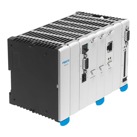
Controller Modular CECX
Brand:
Festo
| Category:
Controller
| Size: 7.26 MB
Table of Contents
Cecx Modular Control System
8
Table of Contents
8
CECX Modular Control System
9
Overview of Functions and Libraries
9
Network Configuration
20
Network Configuration[Slot]
20
Control Configuration
21
Adding / Configuring a Module
21
End Points and Status Values of Configured Modules
22
Process Map
23
Address Setting for Modules
25
Cecx-D-14A-2
25
Cecx-D-8E8A-Np-2
26
Cecx-D-6E8A-Pn-2
28
Cecx-A-4E-V
29
Cecx-A-4A-V
30
Cecx-A-4E4A-V
31
Cecx-A-4E4A-A
32
Cecx-E-4E-T-P1
33
Cecx-E-6E-T-P2
34
CECX-F-PB-S-V1 (12 Bytes, 32 Bytes, 64 Bytes)
35
Cecx-F-Pb-V1
36
Cecx-C-2G2
38
Cecx-S-2S1
39
Cecx-C-2G1
40
Cecx-C-S1, Cecx-S-S4
41
Cecx-B-Co
41
CAN Master [SLOT]
43
Bus Interface [SLOT] (for Controller CECX-X-M1)
44
Unused [SLOT]
45
Notes on System Behavior
45
Watchdog Exception
45
Table of Contents
49
Product Design
57
1 Introduction
59
Purpose of the Document
59
Target Groups, Preconditions
59
Intended Use of the CECX Modular Control System
60
Notes on this Document
61
General Product-Specific Terms and Abbreviation
61
Application and Registrations
62
2 Safety Notes
63
Representation
63
General Safety Instructions
64
Safety Instructions for Programming
66
Safety Instructions for Maintenance Work
67
Requirement for UL508 and Use Conforming to en 61131
67
3 System Overview
69
Structure of the Modular Control
69
Working Mode of the Control
72
Start-Up and Programming (Overview)
73
4 General Assembly and Installation Instructions
77
General Instructions on Assembly and Removal
77
Mounting Rail
77
Footprint
78
Mounting/Dismounting the Boards and Modules
79
Air Conditioning, Ventilation
83
5 Power Supply of Modules
85
Connection
85
Power Consumption of Modules
86
Example Power Calculation
87
6 Operation and Displays
89
Setting the Module Address
89
Control Key (Ctrl)
89
Power LED (Power)
89
Diagnosis Display (Diagnostics)
90
Compact Flash Card
90
7 Commissioning of Codesys and Control
93
Installing Codesys and Starting Development Environment
93
Installation of a Target Support Package (TSP)
93
Switch-On Control
96
Creating a Codesys Project
96
Establishing the Connection to the Pc/Control
97
Configuring Modules
107
Connecting an FED
108
First Programming Steps
112
8 Operating Behavior
113
Button and Display, General Information
113
Start-Up
114
Operating States
115
9 Diagnosis
119
Display of Errors in the 7-Segment Display
119
Touch Control at Error Display During Operations
119
Error Codes
120
10 Disposal
121
Disposal of the Module
121
Disposal of the Battery
121
11 Technical Data
123
12 EC Directives and Standards
125
Why EMC-Compatible Wiring
126
13 Connections and Wiring
129
General Information on Interfaces
129
General Information on Inputs / Outputs
135
General Limits for Wire Cross Sections
139
Test of Interference Immunity
140
14 CPU Module
141
Introduction
141
Safety Notes
141
Description of the Module
144
Operating Elements and Displays
146
Mounting and Installation Instructions
147
Air Conditioning and Ventilation
150
Connections and Wiring
151
Configuration
159
Operating Behavior of the CPU Module
160
Diagnosis
160
Maintenance
161
Disposal
163
Technical Data
164
EC Directives and Standards
165
15 Digital Input Module CECX-D-16E
167
Introduction
167
Safety Notes
167
Description of the Module
169
Connections and Wiring
170
Configuration
175
Operating Behavior
177
Disposal
177
Technical Data
178
EC Directives and Standards
179
16 Digital Output Module CECX-D-14A-2
181
Introduction
181
Safety Notes
181
Description of the Module
183
Connections and Wiring
185
Configuration
188
Operating Behavior
189
Disposal
192
Technical Data
193
EC Directives and Standards
194
17 Digital Input/Output Module CECX-D-8E8A-NP-2
195
Introduction
195
Safety Notes
195
Description of the Module
197
Connections and Wiring
198
Configuration
205
Operating Behavior
206
Disposal
208
Technical Data
209
EC Directives and Standards
211
18 Digital Input/Output Module CECX-D-6E8A-PN-2
213
Introduction
213
Safety Notes
213
Description of the Module
215
Connections and Wiring
217
Configuration
224
Operating Behavior
226
Disposal
228
Technical Data
229
EC Directives and Standards
231
19 Analog Input Module CECX-A-4E-V
233
Introduction
233
Safety Notes
233
Description of the Module
235
Connections and Wiring
237
Configuration
242
Operating Behavior
243
Disposal
244
Technical Data
245
EC Directives and Standards
247
20 Analog Output Module CECX-A-4A-V
249
Introduction
249
Safety Notes
249
Description of the Module
251
Connections and Wiring
253
Configuration
256
Operating Behavior
257
Disposal
257
Technical Data
258
EC Directives and Standards
259
21 Analog Input/Output Module CECX-A-4E4A-V
261
Introduction
261
Safety Notes
261
Description of the Module
263
Connections and Wiring
265
Configuration
272
Operating Behavior
273
Disposal
274
Technical Data
275
EC Directives and Standards
277
22 Analog Input/Output Module CECX-A-4E4A-A
279
Introduction
279
Safety Notes
279
Description of the Module
281
Connections and Wiring
283
Configuration
288
Operating Behavior
289
Disposal
290
Technical Data
291
EC Directives and Standards
293
23 Temperature Module CECX-E-4E-T-P1
295
Introduction
295
Safety Notes
295
Description of the Module
297
Connections and Wiring
299
Configuration
303
Operating Behavior
304
Disposal
304
Technical Data
305
EC Directives and Standards
307
24 Temperature Module CECX-E-6E-T-P2
309
Introduction
309
Safety Notes
309
Description of the Module
311
Connections and Wiring
313
Configuration
317
Functional Description
318
Operating Behavior
321
Disposal
321
Technical Data
322
EC Directives and Standards
324
25 PROFIBUS Master Interface Module CECX-F-PB-V1
325
Introduction
325
Safety Notes
325
Description of the Module
327
Operating Elements and Displays
328
Connections and Wiring
329
Configuration
331
Operating Behavior
331
Disposal
332
Technical Data
333
EC Directives and Standards
334
26 PROFIBUS Slave Interface Module CECX-F-PB-S-V1
335
Introduction
335
Safety Notes
335
Description of the Module
337
Operating Elements and Displays
338
Connections and Wiring
339
Configuration
342
Operating Behavior
342
Disposal
342
Technical Data
343
EC Directives and Standards
344
27 Incremental Encoder Interface Module CECX-C-2G2
345
Introduction
345
Safety Notes
345
Description of the Module
347
Connections and Wiring
349
Configuration
355
Functional Description
357
Operating Behavior
362
Disposal
363
Technical Data
364
EC Directives and Standards
366
28 Serial Interface Module CECX-S-2S1
367
Introduction
367
Safety Notes
367
Description of the Module
369
Operating Elements and Displays
370
Connections and Wiring
371
Configuration
373
Disposal
374
Technical Data
375
EC Directives and Standards
376
29 SSI Interface Module CECX-C-2G1
377
Introduction
377
Safety Notes
377
Description of the Module
379
Operating Elements and Displays
381
Connections and Wiring
381
Configuration
385
Operating Behavior
386
Disposal
386
Technical Data
387
EC Directives and Standards
388
30 CAN Option Module CECX-F-CO
389
Introduction
389
Safety Notes
389
Description of the Module
391
Installation Instructions
392
Display and Operating Elements
394
Connections and Wiring
395
Configuration
398
Operating Behavior
398
Disposal
398
Technical Data
399
EC Directives and Standards
400
31 Serial Option Module CECX-C-S1
401
Introduction
401
Safety Notes
401
Description of the Module
403
Installation Instructions
404
Connections and Wiring
407
Operating Behavior
409
Disposal
409
Technical Data
410
EC Directives and Standards
411
32 Serial Option Module CECX-S-S4
413
Introduction
413
Safety Notes
413
Description of the Module
415
Installation Instructions
416
Connections and Wiring
419
EMC and Wiring Guidelines
422
Operating Behavior
423
Disposal
423
Technical Data
424
EC Directives and Standards
425
33 Ethernet Option Module CECX-C-ET
427
Introduction
427
Safety Notes
427
Description of the Module
429
Installation Instructions
430
Connections and Wiring
433
Configuration
434
Operating Behavior
434
Disposal
434
Technical Data
435
EC Directives and Standards
436
34 Bus Link Module CECX-B-CO
437
Introduction
437
Safety Notes
437
Description of the Module
439
Canopen Protocol
440
Operating Elements and Displays
444
Connections and Wiring
445
Configuration
448
Operating Behavior
458
The Library Ethernet.lib
502
The Library Ethernet.lib
503
Functions
503
Ethgetipconfig
503
Ethsetipconfig
504
The Library Eventdata.lib
506
Functions
507
Getlastintredge
507
Examples
509
Event-Driven Task 'Interrupt Enabled DI Edge Detected
509
System Event 'Di_Edge
509
The Festo_Easyip.lib Library
518
1 The Festo_Easyip.lib Library
519
What Is Easyip
519
Initialisation of Easyip
520
Programs and Functions for Initialising Easyip
520
Easy_Setipaddr
521
Easy_Settimeout
521
Communication Functions
522
Functions for Communicating Via Easyip
522
Easy_S
522
Easy_R
523
Easy_Sr
525
Internally Used Variables, Constants and Help Functions
527
Global Variables
527
Global Constants
528
Ipfrom4Chars
528
Programming
529
Initialisation
529
Sending Telegrams
530
Requesting Telegrams
530
Programming Instructions
531
2 Index
533
3 Glossary
534
The Library Plcservice.lib
536
Functions
537
Plcgetcpuclock
537
The Library Plcservice.lib
537
Plcgetcpuclockrate
538
Plcgetdevicename
538
Plcgetfirmwareversion
539
Plcgethourscounter
539
Plcgetlicenceoption
540
Plcgetserialno
540
Plcgetsystemversion
541
Plcgetvendorname
541
Plcreboot
541
The Festo_Motion.lib Library
548
1 The Festo_Motion.lib Library
549
Overview
549
Architecture
549
Requirements
551
I/O Configuration for PROFIBUS
551
Designated Use
552
Target Group
552
Service
552
Safety Instructions
553
General Information on Festo Motor Controllers
554
Documentation on Festo Motor Controllers
554
Festo Handling and Positioning Profile (FHPP)
555
Operating Modes
555
Function Blocks for Festo Motor Controllers
556
Control Function Blocks
556
Organisation Function Blocks
567
Parameterisation Function Blocks
568
Examples
576
Example for Controlling a Festo Motor Controller
576
Example for Parameterising a Festo Motor Controller
579
2 Glossary
581
3 Index
583
The Festo_Partdetector.lib Library
586
Overview
587
Architecture
587
Configuration
587
Operating Method
588
The Festo_Partdetector.lib Library
587
Requirements
589
Libraries
589
Camera
589
Designated Use
589
Target Group
589
Service
589
Safety Instructions
590
Visualisations
591
General
591
Single Blocks
591
Entire Module
592
Visualisation of the Conveyor
592
Preparations
593
Compact Vision System SBO
593
Checkopti Project
594
Interfaces - Inputs
596
Settings for the Detection of Parts Detected Multiple Times
596
Settings for the Telnet Connection
597
Settings for the Encoder Card
597
Parameters for the Graphical Display of the Conveyor
598
Interfaces - Outputs
599
Fed/Vipwin Interface
602
1 Fed/Vipwin Interface
603
Overview
603
Data Exchange with the Front End Display (FED)
603
Basic Information on Exchanging Data with Feds
603
Exporting PLC Variables (Symbol Configuration and Tag Editor)
603
Configuring the Communication Connection (FED Designer)
607
Importing PLC Variables in FED Designer
612
Exchanging Data with Vipwin Via OPC
617
Basic Information on Exchanging Data with Vipwin Via OPC
617
Installing the OPC and the Gateway Server
621
Configuring the OPC Server
622
Configuring Drivers and Importing Variables with Vipwin
625
2 Index
631
Advertisement
Advertisement
Related Products
Festo Controller CECC
Festo Controller CECC-D
Festo Controller CECC-LK
Festo Controller CECC-S
Festo CECC-X-M1 series
Festo CECC-X-M1-MV
Festo CECC-X-M1-MV-S1
Festo CECX-X-M1 Series
Festo CECX-K-D1
Festo CMMP-AS-***-M0 Series
Festo Categories
Industrial Equipment
Control Unit
Controller
Touch terminals
DC Drives
More Festo Manuals
Login
Sign In
OR
Sign in with Facebook
Sign in with Google
Upload manual
Upload from disk
Upload from URL