Advertisement
Quick Links
Controller
CECC-D/LK/S
Brief description
(Translation of the original instructions)
CODESYS controller
Controller CECC-D/LK/S
1
Use for intended purpose
The CECC-D/LK/S controller is intended exclusively for use in machines or auto
mated systems.
The controller serves as CODESYS controller for
– Controlling pneumatic and electric actuators
– Interrogating electric sensor signals
– Communication via Ethernet
The controller may be used only as follows:
– As intended in industrial environments. Outside of industrial environments,
e.g. in commercial and mixed-residential areas, actions to suppress interference
may have to be taken.
– In its original condition, without unauthorised modifications.
– In faultless technical condition.
– Only in combination with approved components.
– Within the limits of the product defined through the technical data.
– In case of installation in the field, in a separate housing that surrounds
everything, or within an overall housing of the end product.
Take the following into consideration for the destination:
– Regulations and standards
– Regulations of testing organisations and insurers
– National specifications
All notes on intended use, the safety instructions and warnings as well as
all further specifications for the controller also apply to the associated
software libraries.
Additional information:
– On the controller CECC è Description "CECC" è www.festo.com/sp
– On Modbus TCP è www.modbus.org
All available documents for the product è www.festo.com/pk
®
®
CANopen
, CODESYS
, IO-Link
of the respective trademark owners in certain countries.
This product uses open-source software, which is subject to the "GNU General Public
License, Version 2". The terms of the GPL are available within the programming system
as well as at the following address è http://www.gnu.org/copyleft/gpl.html
Training of qualified personnel
The product must only be commissioned by trained experts in control and automa
tion technology who are familiar with:
– Mounting, installation, operation and diagnostics of control systems, networks
and fieldbus systems
– The applicable regulations for accident prevention and occupational safety
– The documentation for the product
Service
Contact your regional Festo contact person if you have technical questions
è www.festo.com
Festo SE & Co. KG
Ruiter Straße 82
73734 Esslingen
Germany
+49 711 347-0
www.festo.com
8060504
2018-04b
[8060506]
®
®
, MODBUS
are registered trademarks
Range of application and certifications
The information in this section, in combination with the UL marking on the product,
must be observed in order for there to be compliance with the certification condi
tions of Underwriters Laboratories Inc. (UL) for USA and Canada è Section 4
Power supply and Section 8 Technical data.
Information on UL certification
Product category code
File number
Valid standards
CE marking
Fig. 1 Information on UL certification
2
Safety
• Prior to mounting, installation and maintenance work:
Switch off power supply and secure it from being switched back on.
English
• For the electric power supply, use only PELV circuits that ensure a reliable elec
tric disconnection from the mains network.
• Observe IEC 602041/EN 602041.
• Connect an earthing cable of sufficient conductor cross section to the connec
tion on the product marked with the earth symbol.
• Observe the handling specifications for electrostatically sensitive devices.
• Only switch on the compressed air and load voltage if the system has been pro
fessionally installed, configured and parameterised.
• When performing maintenance and repair work, use suitable interlocks to pre
vent unintended movements of the actuators.
3
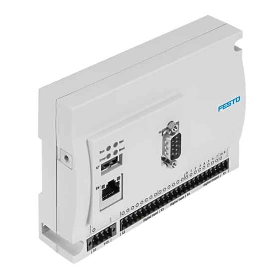
Connection and display components
4
3
2
1
1
X8: Ethernet interface
2
X7: USB interface
3
Functional earth
4
X11: Infeed
Load voltage supply for IO-Link
(CECC-LK and CECC-S)
Operating voltage supply for
encoder (CECC-S)
5
LED displays Run, Error, Net, Mod
Fig. 2 CECC (example CECC-LK)
Plug NECC-L2G... for the interfaces X1
è www.festo.com/catalogue
Note
• Use connecting cables approved for a temperature range up to at least 70 °C.
3.1 I/O interfaces X2
Pin
Explanation
X2.0 ... X2.1
High-speed digital inputs
X2.2 ... X2.7
Digital inputs
X3.0 ... X3.5
Digital inputs
X4.0 ... X4.7
Digital outputs
Fig. 3 I/O interfaces X2
NRAQ (USA)
NRAQ7 (Canada)
E239998
UL 61010-1 Edition 3
UL 61010-2-201 Edition 1
CAN/CSA-C22.2 No. 61010-1-12 Edition 3
CAN/CSA-C22.2 No. 61010-2-201:14 Edition 1
5
6
X12
X16: interfaces
...
IO-Link (CECC-LK and CECC-S)
RS232 and ENC/RS485/RS422
(CECC-S)
7
X6: CANopen fieldbus interface
8
X5: Infeed
Operating voltage supply for I/O
interfaces
9
X2
X4: I/O interfaces
...
(digital input, digital output)
aJ
X1: Operating voltage supply
of the controller
X5 and X11
...
X4 (digital input, digital output)
...
X4
...
6
7
8
9
aJ
X16
...
Advertisement

Related Manuals for Festo CECC-D


Summary of Contents for Festo CECC-D
- Page 1 Use for intended purpose • Observe IEC 602041/EN 602041. The CECC-D/LK/S controller is intended exclusively for use in machines or auto • Connect an earthing cable of sufficient conductor cross section to the connec mated systems.
- Page 2 1) If the controller is at the end of the cable: Connect pin 2 and pin 7 using a terminating resistor (120 ohms/0.25 W). Designation/ Explanation Appropriate CAN bus plugs (adapters) from Festo è www.festo.com/catalogue signal Fig. 4 Fieldbus interface X6 X15.1 Operating voltage supply (24 V) X15.2...
- Page 3 4.1 Operating voltage supply X1 (V-El.) Mounting, dismounting • Prior to mounting, installation and maintenance work: Designation/ Explanation Switch off power supply and secure it from being switched back on. signal • Mount the controller on an H-rail (è 5.1) or on the wall (è 5.2). X1.1 Operating voltage supply (+24 V DC) X1.2...
-
Page 4: Technical Data
– 5.875 A 3.5 A Fieldbus interface X6 supply X11 Type CAN bus CE marking è www.festo.com/sp 2),3) In accordance with EU EMC Directive è Declaration of conformity Connection technology Plug, Sub-D, 9-pin Transmission rate 10, 20, 50, 100, 125, 250, 500, 800, 1000 kBit/s... - Page 5 No error/class 1 error (encoder ticks) Flickers Encoder rotates quickly green Flashes Controller has been Identification, e.g. through Festo identified in Field Device Tool (FFT) Flickers Received data with Display of data transmission the network green RS422 –...
Need help?
Do you have a question about the CECC-D and is the answer not in the manual?
Questions and answers