
Related Manuals for Festo CECC-X-M1 series


Summary of Contents for Festo CECC-X-M1 series
- Page 1 Controller CECC-X-M1 Brief description Controller CECCXM1 CECCXM1MV CECCXM1MVS1 8079349 2017-09a [8074647]...
- Page 2 “GNU General Public License, Version 2”. The licensing conditions of the GPL are located either in the product’s engineering tool or at the following address: http://www.gnu.org/copyleft/gpl.html Edition: 2017-09a Original instructions © Festo AG & Co. KG Ruiter Straße 82 73734 Esslingen Germany Internet: http://www.festo.com E-Mail: service_international@festo.com...
- Page 3 System (IPS), network segmentation, virtual LAN (VLAN), virtual private network (VPN), security at physical access level (port security). Further information è Directives and standards on information tech nology security, e.g. IEC 62443, ISO/IEC 27001. An access password protects only against accidental changes. Festo CECC-X-M1-... 2017-09a English...
- Page 4 • Only use the product if it is in an excellent technical status. Note In the event of damage caused by unauthorised manipula tion or other than intended use, the guarantee is invalidated and the manufacturer is not liable for damages. Festo CECC-X-M1-... 2017-09a English...
- Page 5 – installation – commissioning – maintenance – repair The trained personnel must be familiar with: – electrical control technology – the applicable regulations for operating safety-engineered systems – the applicable regulations for accident prevention and occupational safety Festo CECC-X-M1-... 2017-09a English...
- Page 6 Scope of delivery – Controller CECC-X-M1-... – This brief description Software for the product can be found in the Festo Support Portal è www.festo.com/sp. Accessories – Camera – Plug assortment Catalogue è www.festo.com/sp Please consult your regional Festo contact if you have any technical queries or questions regarding the accessories.
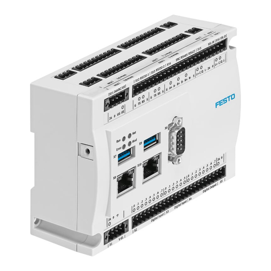
- Page 7 Multi-functional interface CANopen interface CAN 2 Direct connections for motor Digital inputs controller Digital outputs Torque-off input Analogue inputs Load voltage supply for motor I/O interfaces controller Infeed for I/O power supply Fig. 1 Controller CECC-X-M1-... Festo CECC-X-M1-... 2017-09a English...
- Page 8 – above and below the product for connecting cables – to the right of the product for cold-air entry and access to the Mi croSD card slot. 20 mm 122.2 mm Clip Mounting holes Distance Fig. 2 Festo CECC-X-M1-... 2017-09a English...
- Page 9 – Max. tightening torque: 0.8 Nm Dismounting from mounting surface 1. Loosen two M4 screws. 2. Remove the product from the mounting surface. Additional information regarding installation and commissioning can be found in the Festo Support Portal è www.festo.com/sp. Festo CECC-X-M1-... 2017-09a English...
- Page 10 750 mA Residual current for all supplied ports: 200 mA of which intrinsic current consumption: Terminal Port Comments X1.1 U+ power supply X1.2 U– load ’ X1.3 Functional earth X1.4 – Not connected Fig. 4 Festo CECC-X-M1-... 2017-09a English...
- Page 11 If there is a load on all digital outputs of 0.5 A each, the residual cur rent can be exceeded as soon as additional consuming devices are used. • Consider all current loads. • For special configurations, contact the local Festo service. Festo CECC-X-M1-... 2017-09a English...
- Page 12 UA– Infeed for IO-Link master port X15.5 Fig. 7 Power supply [X11] for encoder 0.3 A Encoder current consumption: Termi Port Comments X11.3 Encoder power supply (ground) X11.4 Encoder power supply (5 V) Fig. 8 Festo CECC-X-M1-... 2017-09a English...
- Page 13 2) X2.3 also serves as a latch input for the encoder via the multiple interface X14 3) X4.0 ... X4.2 optionally also serve as MachineVision outputs (e.g. flash output) 4) SSR: Solid State Relay Fig. 10 Festo CECC-X-M1-... 2017-09a English...
- Page 14 Not connected 1) For connection of the device at the end of the line: Connect Pin2 and Pin7 via a resistor. A corresponding plug with resistor (120 Ω/0.25 W) can be found in Festo's accessor ies è www.festo.com/catalogue Fig. 11 USB interfaces [X7, X9] The USB interfaces è...
- Page 15 Comments X12.1, X13.1 Load X12.2, X13.2 Transmitted data (output) X12.3, X13.3 Received data (input) X12.4, X13.4 Screening, connection to functional earth 1) Max. level: low –15 V high +15 V; TTL level not permissible! Fig. 13 Festo CECC-X-M1-... 2017-09a English...
- Page 16 2) If the device is connected at the end of the cable: Connect terminals X14.2 and X14.3 via resistor (120 Ω/0.25 W). 3) If the device is connected at the end of the cable: Connect terminals X14.4 and X14.5 via resistor (120 Ω/0.25 W). Fig. 14 Festo CECC-X-M1-... 2017-09a English...
- Page 17 Communication interface for IO-Link [X15, X16] IO-Link Master Terminal Port Comments X15.1 24 V X15.2 IO-Link communication signal X15.3 L– X15.4 X15.5 UA– Fig. 15 IO-Link device Terminal Port Comments X16.1 24 V X16.2 IO-Link communication signal X16.3 L– Fig. 16 Festo CECC-X-M1-... 2017-09a English...
- Page 18 X18.1 X2x.6 CAN2_L CANBus signal 2 (dominant low) X18.2 X2x.7 CAN_GND CAN Ground X18.3 X2x.8 CAN_SHLD Connection to functional earth X18.4 1) Continuous load per output: 2.0 A Impulse current per output: 4.2 A Festo CECC-X-M1-... 2017-09a English...
- Page 19 24 VDC Power supply X2x.2 Signal Multi-functional signal X2x.3 Load Fig. 19 10.3 Torque-off input [X25] Terminal Port Comments X25.1 Signal Torque-off input X25.2 24 VDC Power supply Fig. 20 Load voltage supply [X21] è 8.3. Festo CECC-X-M1-... 2017-09a English...
- Page 20 (1 kHz, IEC type 1) X17.1.2 Signal 2 / home signal for drive C X17.1.3 GND logic Connection for digital sensor 3 X17.2.1 24 VDC (1 kHz, IEC type 1) X17.2.2 Signal 3 X17.2.3 GND logic Festo CECC-X-M1-... 2017-09a English...
- Page 21 CANBus signal 2 (dominant high) X18.2 CAN2_L CANBus signal 2 (dominant low) X18.3 CAN_GND CAN Ground X18.4 CAN_SHLD Connection to functional earth 1) No terminating resistor necessary; ports are connected internally via a resistor. Fig. 23 Festo CECC-X-M1-... 2017-09a English...
- Page 22 Fig. 24 The inputs can be operated either with voltage signal (0 ... 10 V) or current signal (0 ... 20 mA). Configuration is made via CODESYS parameters in the control project for each input separately. Festo CECC-X-M1-... 2017-09a English...
- Page 23 X20.1.2 Signal N Port output 3 X20.2.1 Signal P (0.5 A per channel, SSR) X20.2.2 Signal N Port output 4 X20.3.1 Signal P (0.5 A per channel, SSR) X20.3.2 Signal N 1) SSR: Solid State Relay Festo CECC-X-M1-... 2017-09a English...
- Page 24 Mass storage card slot è Fig. 1 aB Supported MicroSD cards – microSD – microSD HC – microSD XC Supported functions – Storage of boot projects and check programs (only CECC- X-M1-MV/-S1) – General data storage Festo CECC-X-M1-... 2017-09a English...
- Page 25 Measures for interference suppression may need to be implemented in residential areas. 2) The product is classified in zone A in accordance with EN 61131-2:2007. 3) è 13.2 Explanation on vibration and shock – severity level Festo CECC-X-M1-... 2017-09a English...
- Page 26 0 bytes (only if there is no PERSISTENT variable list) bytes 4052 (44 bytes for identification) bytes 4052 – 300 bytes = 3752 bytes (44 bytes for identification) bytes 4052 – x bytes (44 bytes for identification) Fig. 28 Festo CECC-X-M1-... 2017-09a English...
- Page 27 4096 bytes. This will avoid errors when transferring an application to the control ler. Additional information can be found in the Festo Support Portal è www.festo.com/sp. Festo CECC-X-M1-... 2017-09a English...
- Page 28 160 … 200 160 … 200 – – Fig. 29 Shock load Acceleration [m/s Duration [ms] Shocks per direction ±150 ±300 Fig. 30 Continuous shock load Acceleration [m/s Duration [ms] Shocks per direction ±150 1000 Fig. 31 Festo CECC-X-M1-... 2017-09a English...
Need help?
Do you have a question about the CECC-X-M1 series and is the answer not in the manual?
Questions and answers