Table of Contents
Advertisement
Quick Links
Advertisement
Table of Contents

Related Manuals for Festo Controller CECC


Summary of Contents for Festo Controller CECC
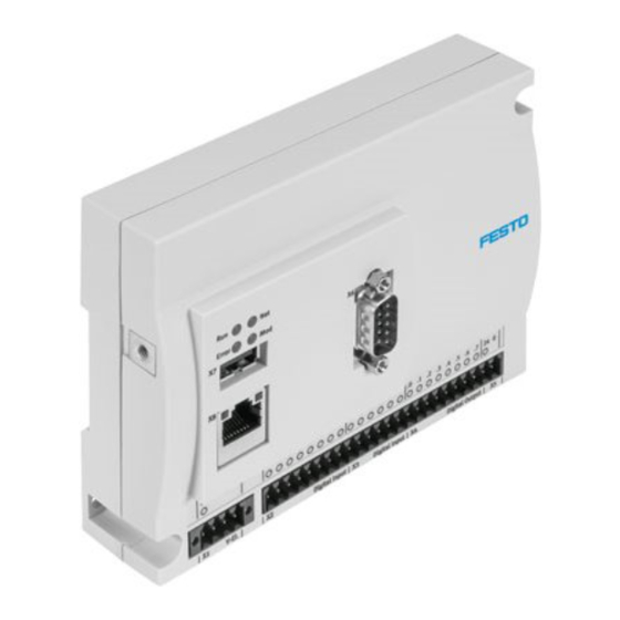
- Page 1 Controller CECC Description Controller CECC 8036062 en 1403a...
- Page 2 This product uses open−source software which is subject to the "GNU General Public License, Version 2". The licens- ing conditions of the GPL are located either in the product’s engineering tool or at the following address: http://www.gnu.org/copyleft/gpl.html – (Festo AG & CO. KG, D-73726 Esslingen, 2014) Internet: http://www.festo.com E-Mail: service_international@festo.com Reproduction, distribution or sale of this document or communication of its contents to others without express authorization is prohibited.
-
Page 3: Table Of Contents
1.3.2 Text markings ......................... 2 1.3.3 Further conventions ....................... 3 1.4 Version information ........................3 System overview ..........................4 2.1 Controller CECC .......................... 4 2.2 Festo Service ..........................4 2.3 Programming software ......................... 5 2.3.1 Packages ........................5 2.3.2 Remanent variables ....................... 5 2.4 Overview of memory size ...................... - Page 4 Table of Contents 4.5 Configuring a CANopen slave ....................30 4.5.1 Adding a CANopen slave ..................... 30 4.5.2 Integrating CPV terminals .................... 34 4.6 Configuring RS232 interfaces (CECC-S) ................... 35 4.7 Configuring an encoder (CECC-S) ..................... 35 4.7.1 Integration ........................35 4.7.2 Parameterisation ......................
-
Page 5: Important Information
Important information Designated use The controller CECC documented in this manual is exclusively intended for installation in a machine or automated system. The device is used for: controlling pneumatic and electric drives – interrogating electric sensor signals – communication via Ethernet. -
Page 6: Target Group
This manual is intended exclusively for technicians trained in control and automation technology, who have experience in installing, commissioning, programming and diagnosing positioning systems. 1.1.3 Service Please contact your local Festo Service partner if you have any technical problems ( http://www.festo.com). Important user information 1.2.1... -
Page 7: Further Conventions
If the right-hand mouse button is to be used, this will be explicitly mentioned. Version information The manual refers to the following versions: Festo controller CECC – firmware version 1.3.4.0 and later – CODESYS V3 provided by Festo (pbF) software package –... -
Page 8: System Overview
The current version of the software package can be found in the download area under www.festo.com/download. Festo Service The following information and data is required for speedy handling of a support inquiry by Festo Service: Response to the command "getdevinfo" ( PLC shell) –... -
Page 9: Programming Software
2.3.1 Packages The associated CECC package is required to use the controller CECC (target system) under CODESYS V3 pbF. This package enables the system functions of the target system to be accessed with the help of libraries and contains corresponding information in the form of online Helps. This enables Codesys functions to be used for the target system or, if necessary, restrict it. -
Page 10: Libraries
For controlling and parameterising the IO-Link devices. Festo_EasyIP_3.library For simple networking of controllers via EasyIP. Festo_Motion_3.library For configuring motor controllers from Festo (e.g. CMMP-AS). Festo_CVE_3.library For actuating motor controllers that support the CVE protocol from Festo (e.g. CMMO-ST). Festo_CameraControl_3.library For accessing the Compact Vision System SBO...-Q. -
Page 11: Installation
The controller CECC only supports single-channel switch-off. All inputs and outputs are de- energised when the power supply is switched off. Mounting and removal The controller CECC is suitable for mounting on an H-rail as well as for wall mounting. Note •... - Page 12 Festo Controller CECC Removal Note • Never remove the CECC from the H-rail while it is still wired. • Make sure that all cable connections are disconnected before removing the CECC. Figure: Removal from an H-rail Removal instructions: Pull the mounting clip 2 on the CECC in the direction of the arrow using a suitable tool (e.g.
-
Page 13: Wall Mounting
Festo Controller CECC 3.2.2 Wall mounting The controller CECC has two holes for wall mounting. Mounting Note Mounting the CECC on uneven, flexible surfaces can result in damage. • The CECC must only be mounted on flat, torsionally rigid surfaces. -
Page 14: Connection And Display Components
Festo Controller CECC Connection and display components 1 Functional earth ’ 8 I/O power supply 2 CECC-LK: Provides load voltage supply for IO-Link 9 I/O interface CECC-S: Provides load voltage supply for IO-Link and power supply for encoder 3 CECC-LK: IO-Link communication interface... -
Page 15: Power Supply X1
Festo Controller CECC Power supply X1 The connection for the power supply to the CECC (24 V) is located on the left on the lower contact strip (X1). Figure: Power supply to the CECC This connection also provides the power supply for the following interfaces: CANopen ... -
Page 16: Interfaces
Use connection 5 for the power supply to the E/A interfaces. • Connect the digital inputs and outputs to sensors and actuators. Appropriate contact strips can be found at www.festo.com/catalogue. Further information on using the I/O interface can be found in the online Help for the Festo CECC_3 library. -
Page 17: Canopen X6
Festo Controller CECC 3.5.2 CANopen X6 The controller CECC has a CANopen interface with CANopen master functionality for connecting CANopen slaves. The CANopen interface is designed as a 9-pin Sub-D plug. CAN bus plug Signal Comment n.c. Not connected CAN_L... -
Page 18: Usb Interface X7
• Use cables with a diameter of 5 ... 8 mm. A CAN bus plug from Festo is a convenient way of connecting the CECC. You can disconnect the plug from the node without interrupting the bus cable (T-TAP function). -
Page 19: Ethernet Interface X8
Festo Controller CECC 3.5.4 Ethernet interface X8 The Ethernet interface enables a PC or operator unit CDPX to be connected to the controller CECC. The Ethernet interface is designed as an RJ45 socket. Socket Signal Comment Transmitted data+ TD– Transmitted data–... -
Page 20: Rs232 Interfaces X12 And X13 (Cecc-S)
Festo Controller CECC 3.5.5 RS232 interfaces X12 and X13 (CECC-S) The controller CECC-S has two RS232 interfaces. Serial interface RS232-1 Serial interface RS232-2 Figure: CECC-S, top manifold rail with RS232 interfaces Signal Comment X12 ... X13.1 Data reference potential X12 ... X13.2 Transmitted data X12 ... -
Page 21: Encoder/Rs422/Rs485 X14 (Cecc-S)
Festo Controller CECC 3.5.6 Encoder/RS422/RS485 X14 (CECC-S) The controller CECC-S has a combined interface with the following connection options: Encoder (ENC, RS422-based encoders only) – RS422 – RS485 – UG/UE power supply for external encoder (5 V, max. 100 mA) -
Page 22: Io-Link (Cecc-Lk And Cecc-S)
Festo Controller CECC 3.5.7 IO-Link (CECC-LK and CECC-S) The following variants of the controller CECC have IO-Link connections. Number of IO-Link connections IO-Link master IO-Link device CECC-LK CECC-S One IO-Link device can be connected to each IO-Link master. The CECC with a higher-order IO-Link master can be connected to the IO-Link device connection. -
Page 23: Io-Link On The Cecc-Lk
Festo Controller CECC 3.5.8 IO-Link on the CECC-LK IO-Link load voltage supply X11 IO-Link master ports for connecting IO-Link devices X12 ... X15 2...5 IO-Link device port for connecting the CECC-LK as an IO-Link device X16 Figure: CECC-LK, top manifold rail with IO-Link interfaces... -
Page 24: Io-Link On The Cecc-S
Festo Controller CECC 3.5.9 IO-Link on the CECC-S IO-Link load voltage supply X11 IO-Link master port for connecting an IO-Link device X15 IO-Link device port for connecting the CECC-S as an IO-Link device X16 Figure: CECC-S, top manifold rail with IO-Link interfaces... -
Page 25: Operator Unit Cdpx
Festo Controller CECC Operator unit CDPX The operator unit CDPX is a display for executing and monitoring automation tasks at the field level. • Note the accompanying user documentation when installing the device. Figure: CECC with operator unit CDPX •... -
Page 26: Commissioning
Connect the PC to the CECC directly via the Ethernet interface or indirectly via a switch/hub. Getting started • Launch CODESYS V3 pbF. You will find the program on your Windows PC in the Start menu directory [Programs] [Festo Software] [CODESYS V3]. 4.2.1 Creating a project •... -
Page 27: Selecting A Device
Festo Controller CECC 4.2.2 Selecting a device Select the relevant device in the "CECC Project" dialog. • Check the "Show all device versions" box for an extended selection of older device variants. The respective version of the relevant device description file is appended to the name of the selected device. - Page 28 Festo Controller CECC The CODESYS V3 pbF program window opens with the newly created project. 1 Device window with CECC, its interfaces and PLC logic 2 Editing window with tabs for the objects activated in the device window 3 Message window with information about the CECC as well as error messages and warnings...
-
Page 29: Adding A Device
If these criteria are not met, the device must be detected using the Festo scan program ( section "Scan Festo Devices"). The network settings for the device can be read out in the scan program and changed to suit your company network. -
Page 30: Manually Adding A Device
Festo Controller CECC 4.2.4 Manually adding a device You can also manually add a known device as an alternative to automatic selection. Highlight the local gateway. Click the "Add device..." button. Figure: "Add device" dialog Enter the name, node address or IP address of the device to be connected in the "Add device" dialog and confirm your entries by clicking "OK". -
Page 31: Setting The Communication Channel
Festo Controller CECC 4.2.5 Setting the communication channel You need a communication channel to exchange data with the connected CECC. • Highlight the desired device and click the "Set active path" button or double-click the highlighted device. The currently active path is shown in bold in the list and "(active)" is appended to the name. -
Page 32: Scan Festo Devices
Festo Controller CECC Scan Festo Devices To launch the scan program "Scan Festo Devices": 1. Click the icon in the toolbar of the Codesys program window. 2. Click the menu command [Online] [Scan for]. Figure: "Scan Festo Devices" scan program Select the device type "CECC"... -
Page 33: Configuring The I/O Interface
Festo Controller CECC Configuring the I/O interface Highlight the "Digital Inputs" or "Digital Outputs" interfaces under the "Onboard" branch in the CODESYS V3 pbF device window. Figure: Device window - Onboard I/O interface Double-clicking the highlighted interface "Digital Inputs" opens a new tab in the editing window for configuring the inputs of the I/O interface. -
Page 34: Configuring A Canopen Slave
Festo Controller CECC Click the "Digital Outputs I/O Mapping" sub-tab to show the current values for the inputs. Figure: Digital outputs I/O mapping Check the "Always update variables" box in offline mode to show the output states in real time. - Page 35 Festo Controller CECC Open the "Add Device" dialog – menu command [Project] [Add Device] or – context menu [Add Device]. Figure: "Add Device" dialog Select a CANopen slave in the device table and highlight it. Example: FB14 Confirm the selection by clicking the "Add Device" button.
- Page 36 Festo Controller CECC Highlight the added CANopen slave in the device window. Figure: Device window - selecting "FB14" Double-clicking the added device "FB14" or "CO2" opens a new tab in the editing window for configuring the CANopen slave. Figure: Editing window with CANopen slave CO2 •...
- Page 37 Festo Controller CECC The PDO mapping can be found in the sub-tab of the same name. Figure: Editing window with CANopen slave CO2...
-
Page 38: Integrating Cpv Terminals
Festo Controller CECC 4.5.2 Integrating CPV terminals CPV terminals are added to CANopen slaves CO2 (CPV-CO2) as sub-modules ( Adding a CANopen slave - step 3). Highlight the CANopen slave "CO2" in the device window. Open the "Add Device" dialog –... -
Page 39: Configuring Rs232 Interfaces (Cecc-S)
RS232-1 – RS232-2 – • Use the appropriate libraries (e.g. "CAA SerialCom") together with the Festo SerialComEx_3 library to parameterise the serial interfaces. Configuring an encoder (CECC-S) 4.7.1 Integration To use an encoder, the device must be integrated in the controller configuration. - Page 40 Festo Controller CECC Encoder settings Parameter Setting Comment Encoder type Encoder deactivated Activates and presets the encoder – Encoder 90° phase single eval. – Encoder 90° phase double eval. – Encoder 90° phase quad. eval. – Encoder with impulse and direct.
- Page 41 Festo Controller CECC Comparator settings The current position value of the encoder is compared with the upper and lower compare value. The result is immediately set at a digital output of the I/O interface. Parameter Setting Comment Comparator Condition for the The output set under the "Digital Output"...
- Page 42 Festo Controller CECC 1 Upper compare value = 10 6 Signal curve for "Counter value within compare values" 2 Lower compare value = -10 7 Signal curve for "Counter value outside compare values" 3 Signal curve for "counter value = lower 8 Signal curve for "counter value = lower compare...
- Page 43 Festo Controller CECC 1 Compare value 3 Signal curve at the digital output 2 Hysteresis Figure: Digital output as a function of the "Hysteresis" parameter Latch settings A buffer memory (latch) can be used to record the position value of the encoder when an external signal (latch result) occurs.
- Page 44 Festo Controller CECC Reference mode settings The reference point can be changed when an external signal occurs or using the zero track. This enables e.g. the current encoder value to be set to 0 when a limit switch is exceeded.
-
Page 45: Encoder Inputs And Outputs
Festo Controller CECC 4.7.3 Encoder inputs and outputs In addition to the actual position value, the encoder also supplies other values that are available as inputs and outputs. Figure: Encoder port I/O mapping Input/output Comment Current value Current encoder position value. -
Page 46: Sample Program
Festo Controller CECC 4.7.4 Sample program CASE state OF %QD5 := 1000; //change referencing value to 1000 %QX16.0 := TRUE; //release referencing state := 10; IF %QX16.0 = FALSE THEN //wait for referencing state := 20; //actual value equals 1000... -
Page 47: Configuring An Io-Link Master (Cecc-Lk And Cecc-S)
Note To use the IO-Link interface you need the IODD file for the relevant IO-Link device. • Festo device: Download the IODD file from the Festo Support Portal (www.festo.com Support). • Third-party device: Request the IODD file from the respective vendor. - Page 48 Festo Controller CECC Figure: IO-Link master editing window (using the example of the CECC-LK) The sub-tabs contain the following information and setting options: Sub-tab Comment IO-Link Master Validation setting: Read in the serial number Options Data storage: Save the parameters –...
-
Page 49: Selecting An Io-Link Device
Festo Controller CECC 4.10.2 Selecting an IO-Link device Highlight an "Empty" placeholder in the "IO-Link Master" branch in the device window for an IO-Link device to be connected. Figure: Device window - selecting "Placeholder"... - Page 50 Festo Controller CECC Open the context menu (right mouse button) and open the "Plug Device" dialog. Figure: "Plug Device" dialog Actions in the "Plug Device" dialog Action Comment Append device Select device for connecting to the selected connection. Insert device Does not work, since the number of connections is clearly defined.
- Page 51 Festo Controller CECC Select another/unoccupied connection for a further IO-Link device in the device window (only with CECC-LK, max. 4). The "Plug Device" dialog must be left open for this. If necessary, repeat from step 3 onwards to plug further IO-Link devices (only with CECC-LK, max. 4).
-
Page 52: Scanning For An Io-Link Device
Festo Controller CECC 4.10.3 Scanning for an IO-Link device Instead of manually selecting an IO-Link device, you can also have Codesys find it by scanning. Prerequisites: There is a (temporary) connection to the device via the active path. – CODESYS V3 pbF has been logged into the device at least once ( section "Online mode"). -
Page 53: Configuring An Io-Link Device
Festo Controller CECC 4.10.4 Configuring an IO-Link device Highlight a plugged device in the "IO-Link Master" branch in the device window (here: VTUB-12 8 Valves). Figure: Device window - selecting "Added IO-Link Device" Double-clicking the plugged device opens a new tab in the editing window for configuring the respective IO-Link device. -
Page 54: Configuring An Io-Link Device (Cecc-Lk And Cecc-S)
To use the IO-Link interface you need the associated IODD file (not with CAPC). • Download the IODD file for the CECC from the Festo Support Portal (www.festo.com Support). Highlight the "IO-Link Device" branch in the CODESYS V3 pbF device window. - Page 55 Festo Controller CECC The sub-tabs contain the following information and setting options: Sub-tab Comment IO-Link Device Shows the IO-Link specification Settings Data width for the process data – Baud rate for the data transmission – I/O Mapping Current process data for the controller as an IO-Link device.
-
Page 56: Configuring Modbus Tcp
Festo Controller CECC 4.11 Configuring Modbus TCP The controller CECC supports Modbus TCP Client as well as Modbus TCP Server. Operation with Modbus TCP Server is restricted to 8 simultaneously usable channels. Detailed information on Modbus TCP can be found in the online Help for CODESYS V3 pbF. - Page 57 Festo Controller CECC Highlight the new "Ethernet" branch in the device window. Add a "Modbus TCP Master" module via the context menu. Figure: Device window - selecting "Modbus TCP Master" in the "Ethernet" branch Highlight the new "Modbus TCP Master" branch and add the "Modbus TCP Slave" module using the context menu.
- Page 58 Festo Controller CECC Several tabs for parameterising the selected "Modbus TCP Slave" are displayed in the workspace. Figure: Workspace for "Modbus TCP Slave" (parameters) 10. Enter the IP address for the Modbus TCP slave. 11. Enter the unit ID for the Modbus TCP slave.
- Page 59 Festo Controller CECC Using the CECC as a Modbus TCP slave provides access to the range %QW with access type Read Input Registers (function code 04) – access to the range %IW with access type Write Multiple Registers (function code 16) –...
- Page 60 Festo Controller CECC This gives the master an I/O map for the slave. Figure: Workspace for "Modbus TCP Slave" - tab "Modbus TCP Slave I/O Mapping" If the timeout option is activated and if this has a value greater than zero, the holding register values (%IW) are automatically reset after this time WITHOUT further remote access to the holding register range.
-
Page 61: Cecc As A Modbus Tcp Slave
Festo Controller CECC 4.11.2 CECC as a Modbus TCP slave Highlight the "Ethernet" branch and add the module "Modbus TCP Slave Device" via the context menu. Figure: Device window - selecting "Modbus TCP Slave" in the "Ethernet" branch Highlight the branch of the device being parameterised as a "Modbus TCP Slave Device". -
Page 62: Online Mode
Festo Controller CECC 4.12 Online mode Caution Risk of injury due to uncontrolled movements of the connected actuators. • Test projects and programs without active actuators initially. A configured project including program (CECC application) is to be transferred to the CECC. Online mode must be activated for transfer, i.e. - Page 63 Festo Controller CECC Once online mode is active, the connection to the CECC as well as the application are highlighted in green in the device window. The CECC is online, the application is not started (not running), the "Run" status LED lights up yellow.
-
Page 64: Starting And Monitoring The Application
Festo Controller CECC 4.12.2 Starting and monitoring the application The application can be started on the CECC if error-free data has been transferred. Use one of the following commands to start the application: Click the icon in the toolbar of the Codesys program window –... -
Page 65: Manually Setting I/Os
Festo Controller CECC 4.12.3 Manually setting I/Os The editing window contains the online views for all program modules and offers the following options: Writing and forcing variables – Using monitoring lists – Troubleshooting in applications (debugging) – Example: IO-Link with VTUB_12 16 valves Open the "IO-Link I/O Mapping"... -
Page 66: Plc Shell
Festo Controller CECC 4.13 PLC shell The PLC shell is a text-based controller monitor (terminal). Commands for requesting certain information from the controller are entered in an input line and sent to the controller as a string. The returned response string is displayed in a results window in the browser. - Page 67 Festo Controller CECC Command Comment reboot Reboots the device. getrtc Shows the current real-time clock data. setrtc YYYY-mm-dd-HH:MM:SS Sets the current real-time clock data Example: setrtc 2011-01-25-15:13:26 canlog Functions for CAN logging. Use the /? option to display the possible parameters.
-
Page 68: Transferring Project Data Using A Usb Memory Stick
Festo Controller CECC 4.14 Transferring project data using a USB memory stick The CECC supports reading in project data via the USB interface. Prerequisites for transferring a project from a USB memory stick without any errors. Firmware version 1.3.4.0 or later –... -
Page 69: Diagnostic Options In The Event Of Errors
Festo Controller CECC 4.14.1 Diagnostic options in the event of errors Check the status of the error LED ( Status LEDs) – Query using FFT ( Festo Field Device Tool) – Create a log file – 4.14.2 Querying using FFT... -
Page 70: Node Guarding
Festo Controller CECC 4.15 Node guarding Node guarding telegrams can be interrupted in stop mode when using the CAN interface. Open the "PLC settings" tab in the CECC controller. Check the "Update IO while in stop" box. Figure: PLC settings for CECC controller 4.16 Data incompatibility between the runtime project and controller... -
Page 71: Diagnostics
200 ... 255 Warning 1 ... 127 Error 128 ... 199 1) The Festo Field Device Tool (FFT) program can be downloaded via the Festo Support Portal www.festo.com. Table: Error evaluation options Figure: Editing window with "Device" tab - "Log" sub-tab... - Page 72 Festo Controller CECC Error message Error Error Remedy class IoDrv: Overload Warning Check the outputs for possible short circuit. IoDrv: IO power supply Warning Check the I/O power supply. failure Undervoltage in power Warning Check the power supply. supply Error loading bootproject Warning Check your boot project.
-
Page 73: Status Leds
Festo Controller CECC Status LEDs The LEDs on the CECC indicate the operating status of the device and are arranged in five groups. 1 IO-Link (CECC-LK) 2 Operation (Run, Net, Error, Mod) 3 Ethernet 4 Power supply to the device (24 V) - Page 74 Festo Controller CECC 1 RS232, multiple interface ENC/RS422/RS485 and IO-Link 2 Operation (Run, Net, Error, Mod) 3 Ethernet 4 Power supply to the device (24 V) 5 I/O (inputs and outputs) and power supply for I/O Figure: Status LEDs on the CECC-S...
- Page 75 Festo Controller CECC Sequence Meaning Comment RS232-1/-2 Lights up green CECC sending data Data transmission RS232-1/-2 Lights up green CECC receiving data Multiple Flashes green Encoder tics track A LED flashing in time with the interface A+ frequency of rotation.
-
Page 76: Technical Appendix
Festo Controller CECC Technical appendix Technical data Feature CECC Certification C-Tick Operating voltage CECC-LK 19.2 ... 30 V DC and CECC-D Operating voltage CECC-S 20.4 ... 30 V DC Current consumption 100 mA nominal at 24 V DC Ambient temperature 0 ... - Page 77 Festo Controller CECC Feature CECC Digital outputs Number – Switching logic Positive logic (PNP) – Contact Transistor – Output voltage 24 V DC – Output current 500 mA – Electrical isolation Yes, via optocoupler – Switching frequency Max. 1 kHz –...
- Page 78 Data transmission speed 10/100 Mbit/s – Supported protocols TCP/IP, EasyIP, Modbus TCP – Programming software CODESYS provided by Festo (pbF) Programming language To IEC 61131-3 SFC, IL, FCH, LDR, ST CE symbol (see declaration of To EU EMC Directive 1),2) conformity) 1) The device is intended for use in industrial areas.
-
Page 79: Glossary
CANopen: CAN-based fieldbus protocol standardised as a European standard. CODESYS pbF: CODESYS provided by Festo allows the configuration, commissioning and programming of different Festo components and devices. It is called "CODESYS pbF" for short in this online Help/manual. Codesys target system ID: See target system ID. - Page 80 Festo Controller CECC Package: All of the configuration and expansion files that are required to make a specific controller (target system) usable for the Codesys programming environment are combined in a package. PLC: Programmable logic controller. Target system ID: Unique device type code. Projects can only be uploaded to controllers if the set device type matches.
Need help?
Do you have a question about the Controller CECC and is the answer not in the manual?
Questions and answers