Sign In
Upload
Manuals
Brands
Sutter Instrument Manuals
Laboratory Equipment
P-2000
Sutter Instrument P-2000 Manuals
Manuals and User Guides for Sutter Instrument P-2000. We have
1
Sutter Instrument P-2000 manual available for free PDF download: Operation Manual
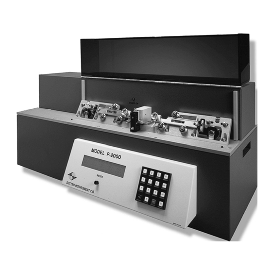
Sutter Instrument P-2000 Operation Manual (88 pages)
Laser-Based Micropipette Puller System
Brand:
Sutter Instrument
| Category:
Laboratory Equipment
| Size: 1 MB
Table of Contents
Disclaimer
5
Laser Safety Warning
5
Safety Warning Labels
6
General Safety Warnings and Precautions
7
Electrical
7
Avoiding Electrical Shock and Fire-Related Injury
7
Back Injury Prevention
8
Handling Micropipettes
8
Table of Contents
9
1 General Information
15
Introduction
15
Technical Support
15
Information Labels
16
Glassware Specifications
16
Mechanical Description (Puller Anatomy)
16
Some Basic Information
16
Figure 1-1. Information Labels on the Back of the P-2000 Cabinet
16
Upper Cable Pulley Assembly
17
Figure 1-2. Upper Cable Pulley Assembly
17
Retro-Mirror Assembly
18
Figure 1-3. Puller Bar Styles
18
Optical Pathway
19
Figure 1-4. Retro Mirror Assembly
19
Figure 1-5. Optical Pathway (Top View Without Laser Housing)
20
Figure 1-6. Optical Pathway (Viewed from Right End of Cabinet; Shroud, Laser and Laser Housing Not Shown)
21
Cabinet
22
Figure 1-7. Cabinet Components
22
2 Installation
23
Unpacking
23
Setting up
23
Removing the Shipping Screw
23
Line Power (Mains)
24
Figure 2-1. Location of Shipping Screw
24
Figure 2-2. P-2000 Cabinet (Rear View)
24
Figure 2-3. P-2000 Cabinet (End View, Left)
25
Figure 2-4. Power Connection
25
3 Operations
27
First Time Use
27
Figure 3-1. Left Puller Bar
27
Front Panel
29
Controls
29
Figure 3-2. P-2000 Front Panel
29
Display
30
Figure 3-3. LCD Display (Program Information)
30
Figure 3-4. LCD Display (Program Parameters)
31
Programs
32
Program Structure
32
Cycle Parameters
32
Table 3-1. FILAMENT Scan Pattern Values
33
Pull Cycle
34
Figure 3-5. Pull Cycle When DELAY Is Greater than 128
34
Default Configuration
35
Figure 3-6. Pull Cycle When DELAY Is Less than 128
35
Table 3-2. Standard Factory Configuration
35
Figure 3-7. Power-On Display
36
Selecting a Program [0 to 99]
36
Table 3-3. Default Programs
36
Clearing a Program from Memory [CLR]
37
Figure 3-8. P-2000 Program (Initial) Display
37
Figure 3-9. Clear Program Display
37
Viewing a Program [NEXT] / [LAST]
37
Editing a Program
38
Entering a New Program
38
Editing an Existing Program
38
Software Control Functions
39
Ramp Test <1
39
Figure 3-10. Access to Control Functions
39
Figure 3-11. Control Function Menu
39
Table 3-4. Control Functions
39
Write-Protect this Prog[Ram] <2
40
Figure 3-12. Insert-Glass, Clamp, and Pull Prompt
40
Figure 3-13. Filament-Selection Prompt
40
Reset Time and Date <3
41
Memory Test <4
41
Figure 3-14. Prompt to Edit or Write-Protect the Program
41
Figure 3-15. Time/Date Minutes Prompt
41
Copy a Program <5
42
Figure 3-16. Initiate-Memory-Test Prompt
42
Figure 3-17. Program-To-Copy and To-Which-Number Prompts
42
Figure 3-18. Message Indicating Program Is Write-Protected and Therefore It Cannot be Changed
42
Pulling Pipettes
43
Procedures
43
Looping
43
Figure 3-19. Pull Cycle Report
43
Figure 3-20. Sample Program
43
Pull Results
44
Notes on Program Operation
45
Heat on
45
Figure 3-21. Pull Cycle Report (Multiple-Loops)
45
Program Memory
46
Parameter Adjustment
46
General Information
46
Micropipette/Microinjection Needle Fabrication
46
Programs
46
Selecting Program Parameters
46
Glass Selection
48
Glass-Specific Parameter Adjustment
48
Sample Programs (for Quartz Glass)
49
Patch Pipette Fabrication
50
Programs
50
Selecting Program Values
50
Glass Selection
51
Glass-Specific Parameter Adjustment
52
Optical System Adjustments
52
Suggested Practices
53
Optic Fiber Fabrication
53
Fiber Preparation
53
Programs
53
Selecting Program Parameters
53
Electrospray/Nanospray Tip Fabrication
54
Glass Preparation
54
Programs
54
Selecting Program Parameters
55
Technical Tips
55
Maintaining Pipette Wall Thickness of Quartz Glass
55
4 Applications and Techniques
57
Pulling very Short Micropipettes
57
Pulling Large-Diameter Glass
58
Background
58
Principles and Strategies
58
Suggested Practices
59
Determining Tip Concentricity
59
Figure 4-1. Mounting the Pipette for Evaluation of Its Geometry
60
Figure 4-2. Field of View When Aligning the Pipette Shaft
61
Figure 4-3. Field of View When Checking the Concentricity
61
5 Maintenance
63
Cleaning
63
Exterior
63
Pull Bars and Pulleys
63
Retro-Reflective Mirror
63
Figure 5-1. V-Groove Bearings and Pull Bars
63
Optical Alignment
64
Scanning Mirror Tilt Adjustment
64
Figure 5-2. Scanning Mirror Tilt Adjustment (from Right End of Cabinet; Shroud, Laser and Laser Housing Not Shown)
64
Reading the Micrometer
65
Figure 5-3. Micrometer Scale
65
Retro-Reflective ("Retro") Mirror Adjustment
66
Figure 5-4. Scanning Mirror Adjustment Using Thermal Paper
66
Figure 5-5. Retro Mirror Adjustment
67
Pulley Adjustment
68
Table 5-1. Pipette Asymmetries and Solutions
68
Figure 5-6. Pulley Adjustment
69
6 Troubleshooting
71
Controlling Pipette Tip Shapes
71
Problem: WHAT GLASS SHOULD I USE: THICK or THIN
71
Problem: the RESISTANCE of MY PIPETTES IS to LOW. HOW DO I PULL a
71
Higher Resistance Pipette
71
Problem: OK, but I STILL WANT a SMALLER TIP than I am GETTING
71
Problem: HOW DO I INCREASE the SIZE of MY PATCH-PIPETTE
71
Problem: the TIPS of MY PATCH-PIPETTES VARY in SIZE from PULL to PULL
71
Problem: ONE ELECTRODE IS MUCH LONGER than the OTHER ELECTRODE
72
Problem: the SHAPE and RESISTANCE of the PIPETTE CHANGES from
72
Pull to Pull
72
Controller Problems
72
Problem: DISPLAY BLANK, FAN NOT on
72
Problem: DISPLAY SHOWS a ROW of BLOCKS
72
Problem: DISPLAYED PROGRAM VALUES ARE NOT CORRECT
73
Technical Support
73
Appendix A. Limited Warranty
75
Appendix B. Accessories
77
Spacers
77
Glass Stops
77
Glass Loading Aids
77
Pipette Storage Boxes
77
Appendix C. Fuse Replacement
79
Figure 6-1. Power Entry Module
79
Figure 6-2. Fuse Holder
79
Table 6-1. Fuse Type and Rating
80
Appendix D. Technical Specifications
81
Table 6-2. Fuse Type and Rating
81
Advertisement
Advertisement
Related Products
Sutter Instrument P-1000
Sutter Instrument P-97
Sutter Instrument P-30
Sutter Instrument Lambda 10-3
Sutter Instrument LAMBDA 10-B
Sutter Instrument Lambda DG-4
Sutter Instrument Lambda DG-5
Sutter Instrument LB10-3
Sutter Instrument MP-225
Sutter Instrument MP-225A
Sutter Instrument Categories
Laboratory Equipment
Amplifier
Control Systems
Controller
Work Light
More Sutter Instrument Manuals
Login
Sign In
OR
Sign in with Facebook
Sign in with Google
Upload manual
Upload from disk
Upload from URL